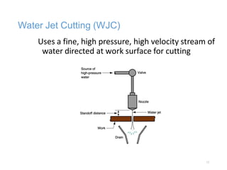
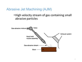
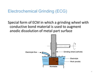
INSTITUTE OF AERONAUTICAL ENGINEERING
(AUTONOMOUS)
DUNDIGAL, HYDERABAD – 500043
MECHANICAL ENGINEERING
UNCONVENTIONAL MACHINING PROCESS
Course Code: A70359 – JNTUH - R15
Prepared By,
S. Srikrishnan
Assistant Professor
1
UNIT I
• Introduction: Need for non-traditional machining methods-
Classification of modern machining processes- considerations in
process selection. Materials, applications.
• Ultrasonic machining – elements of the process, mechanics of metal
removal process parameters, economic considerations, applications
and limitations, recent development.
2
UNCONVENTIONAL MACHINING AND
THERMAL CUTTING PROCESSES
I. Mechanical Energy Processes
II. Electrochemical Machining Processes
III. Thermal Energy Processes
IV. Chemical Machining
3
Unconventional Processes Defined
A group of processes that remove excess material by
various techniques involving mechanical, thermal,
electrical, or chemical energy (or combinations of these
energies) but do not use a sharp cutting tool in the
conventional sense
4
Why Unconventional Processes are
Important
•Need to machine newly developed metals and
non-metals with special properties that make
them difficult or impossible to machine by
conventional methods
•Need for unusual and/or complex part
geometries that cannot easily be accomplished
by conventional machining
•Need to avoid surface damage that often
accompanies conventional machining
5
Classification of Unconventional Processes
by Type of Energy Used
•Mechanical - erosion of work material by a high
velocity stream of abrasives or fluid (or both) is
the typical form of mechanical action
•Electrical - electrochemical energy to remove
material (reverse of electroplating)
•Thermal – thermal energy usually applied to
small portion of work surface, causing that
portion to be removed by fusion and/or
vaporization
•Chemical – chemical etchants selectively remove
material from portions of work part, while other
portions are protected by a mask 6
I. Mechanical Energy Processes
•Ultrasonic machining
•Water jet cutting
•Abrasive water jet cutting
•Abrasive jet machining
7
Ultrasonic Machining (USM)
Abrasives contained in a slurry are driven at high
velocity against work by a tool vibrating at low
amplitude and high frequency
•Tool oscillation is perpendicular to work surface
•Tool is fed slowly into work
•Shape of tool is formed in part
8
Ultrasonic Machining
• Ultrasonic vibration (20,000 Hz) of very
small amplitudes (0.04-0.08 mm) drive
the form tool (sonotrode) of ductile
material (usually soft steel)
• An abrasive slurry is flowed through the
work area
• The workpiece is brittle in nature (i.e.
glass)
• The workpiece is gradually eroded
away.
9
USM Applications
•Hard, brittle work materials such as ceramics, glass,
and carbides
•Also successful on certain metals, such as stainless
steel and titanium
•Shapes include non-round holes, holes along a
curved axis
•“Coining operations” - pattern on tool is imparted
to a flat work surface
10
UNIT II
• Abrasive jet machining, water jet machining and abrasive water jet
machine: Basic principles, equipment's, process variables, mechanics
of metal removal, MRR, application and limitations.
• Electro-Chemical Processes: Fundamentals of electro-chemical
machining, electro-chemical grinding, electro chemical honing and
deburring process, metal removal rate in ECM, Tool design, Surface
finish and accuracy economic aspects of ECM-Simple problems for
estimation of metal removal rate.
11
Water Jet Cutting (WJC)
Uses a fine, high pressure, high velocity stream of
water directed at work surface for cutting
12
WJC Applications
 Usually automated by CNC or industrial robots to
manipulate nozzle along desired trajectory
 Used to cut narrow slits in flat stock such as
plastic, textiles, composites, floor tile, carpet,
leather, and cardboard
 Not suitable for brittle materials (e.g., glass)
 WJC advantages: no crushing or burning of work
surface, minimum material loss, no environmental
pollution, and ease of automation
13
Abrasive Water Jet Cutting (AWJC)
•When WJC is used on metals, abrasive particles
must be added to jet stream usually
•Additional process parameters: abrasive type, grit
size, and flow rate
•Abrasives: aluminum oxide, silicon dioxide, and
garnet (a silicate mineral)
•Grit sizes range between 60 and 120
•Grits added to water stream at about 0.25 kg/min
(0.5 lb/min) after it exits nozzle
14
Abrasive Jet Machining (AJM)
•High velocity stream of gas containing small
abrasive particles
15
Waterjet and Abrasive Waterjet (AWJ) Cutting
16
Abrasive
Waterjet and
Waterjet
examples
17
Abrasive Water Jet
• High pressure water (20,000-60,000
psi)
• Educt abrasive into stream
• Can cut extremely thick parts (5-10
inches possible)
• Thickness achievable is a function of
speed
• Twice as thick will take more than
twice as long
• Tight tolerances achievable
• Current machines 0.002” (older
machines much less capable ~
0.010”
• Jet will lag machine position, so
controls must plan for it
18
AJM Application Notes
•Usually performed manually by operator who
directs nozzle
•Normally used as a finishing process rather than
cutting process
•Applications: deburring, trimming and deflashing,
cleaning, and polishing
•Work materials: thin flat stock of hard, brittle
materials (e.g., glass, silicon, mica, ceramics)
19
IV. Chemical Machining (CHM)
Material removal through contact with a strong
chemical etchant
•Processes include:
•Chemical milling
•Chemical blanking
•Chemical engraving
•Photochemical machining
•All utilize the same mechanism of material removal
20
Chemical Machining (Chemilling)
•Applications:
•Aerospace industry
•Engraving
•Circuit boards
•A maskant is applied over areas
you don’t want to machine
•Photochemical methods
•Apply maskant to entire surface
and use laser to cut
•Place the entire part in a chemical
bath (acid or alkali depending upon
the metal)
•Control temperature and time of
exposure to control material
removal 21
Electro-Chemical
Machining (ECM)
•Works on the principle of
electrolysis – accelerated
chemilling
•Die is progressively lowered
into workpiece as workpiece
is dissociated into ions by
electrolysis
•Electrolytic fluid flows around
workpiece to remove ions
and maintain electrical
current path
•Low DC voltage, very High
current (700 amps)
22
Electrochemical grinding
•Combines electrochemical machining with
conventional grinding
•Grinding wheel is the cathode
•Metal bonded wheel with diamond or Al2O3
abrasive
•Majority of material removal from electrolytic
action (95%) therefore very low wheel wear
•Much faster than conventional grinding
23
UNIT III
• Thermal Metal Removal Processes: General Principle and applications
of Electric Discharge Machining, Electric Discharge Grinding and
electric discharge wire cutting processes-Power circuits for EDM,
Mechanics of metal removal in EDM, Process parameters, selection
of tool electrode and dielectric fluids, surface finish and machining
accuracy, characteristics of spark eroded surface and machine tool
selection. Wire EDM-principle and applications.
24
II. Electrochemical Machining Processes
•Electrical energy used in combination with chemical
reactions to remove material
•Reverse of electroplating
•Work material must be a conductor
•Processes:
•Electrochemical machining (ECM)
•Electrochemical deburring (ECD)
•Electrochemical grinding (ECG)
25
Electrochemical Machining (ECM)
Material removal by anodic dissolution, using
electrode (tool) in close proximity to the work but
separated by a rapidly flowing electrolyte
26
Electrochemical Deburring (ECD)
Adaptation of ECM to remove burrs or round sharp
corners on holes in metal parts produced by
conventional through-hole drilling
27
Electrochemical Grinding (ECG)
Special form of ECM in which a grinding wheel with
conductive bond material is used to augment
anodic dissolution of metal part surface
28
III. Thermal Energy Processes
•Very high local temperatures
•Material is removed by fusion or vaporization
•Physical and metallurgical damage to the new
work surface
•In some cases, resulting finish is so poor that
subsequent processing is required
29
Thermal Energy Processes
•Electric discharge machining
•Electric discharge wire cutting
•Electron beam machining
•Laser beam machining
•Plasma arc machining
30
Electric Discharge Processes
Metal removal by a series of discrete electrical
discharges (sparks) causing localized
temperatures high enough to melt or vaporize the
metal
• Can be used only on electrically conducting work
materials
• Two main processes:
1. Electric discharge machining
2. Wire electric discharge machining
31
Electric discharge machining (EDM): (a) overall
setup, and (b) close-up view of gap, showing
discharge and metal removal
Electric Discharge Machining (EDM)
32
EDM Applications
•Tooling for many mechanical processes: molds for
plastic injection molding, extrusion dies, wire
drawing dies, forging and heading dies, and
sheetmetal stamping dies
•Production parts: delicate parts not rigid enough to
withstand conventional cutting forces, hole drilling
where hole axis is at an acute angle to surface, and
machining of hard and exotic metals
33
Wire EDM
Special form of EDM that uses small diameter wire as
electrode to cut a narrow kerf in work
Electric discharge wire cutting (EDWC), also
called wire EDM 34
Electrode Discharge Machining (EDM)
• Direct Competitor of ECM – much more
common than ECM
• The tool acts as a cathode (typically graphite)
is immersed in a Dielectric fluid with
conductive workpiece
• DC voltage (~300V) is applied. As voltage
builds up over gap between workpiece and
tool, eventually you get dielectric breakdown
(sparking at around 12,000 deg F)
• The sparking erodes the workpiece in the
shape of the tool
• The tool is progressively lowered by CNC as
the workpiece erodes
• Cycle is repeated at 200,000-500,000 Hz
• Dielectric:
• Cools tool and workpiece
• Flushes out debris from work area
35
Die Sinker
vs. Wire
EDM
•Die sinker EDM
• The die sinks into the part as
it sparks away the workpiece
• Most common Injection
molding die process
•Wire EDM
• The electrode is a wire that
traverses through the part
• Common for Extrusion Dies
36
Case Study
•CNC Mill
•CNC Wire EDM
•CNC EDM
37
Wire EDM (not shown), Die Sinker EDM,
Anodized
38
Different Part - Wire EDM – profiling and
drilling
39
Case Study Three
1. CNC Milling 2. Setup on wire EDM
3. QAAfter wire EDM 4. Grinding a face on the part
40
Setup of Die Sinker EDM
1. Locating parts relative to
machine
2. Locating the electrode
relative to parts setup
41
Die Sinker in action and finished product
42
UNIT IV
• Generation and control of electron beam for machining, theory of
electron beam machining, comparison of thermal and non-thermal
processes- General Principle and application of laser beam
machining-thermal features, cutting speed and accuracy of cut.
43
Principle
•A stream of high-speed electrons impinges on the
work surface whereby the kinetic energy,
transferred to the work material, produces intense
heating. Depending on the intensity of the heat
thus generated, the material can melt or vaporize
Laser Beam Machining
•Lasers are high intensity focused light sources
• CO2
• Most widely used
• Generally more powerful that YAG lasers
• Cutting operations commonly
• Nd:YAG (Neodymium ions in an Yttrium Aluminum
Garnet)
• Less powerful
• Etching/marking type operations more commonly
•Limited in depth of cut (focus of light)
•Would limit workpiece to less than 1 inch (< ½”
typically)
49
Laser Beam Machining (LBM)
Uses the light energy from a laser to remove material
by vaporization and ablation
50
UNIT V
• Application of plasma for machining, metal removal mechanism,
process parameters, accuracy and surface finish and other
applications of plasma in manufacturing industries. Chemical
machining-principle- maskants-etchants-applications.
51
Principle
• When heated to elevated temperatures, gases turn into a
distinctly different type of matter, which is plasma
• When gases are heated by an applied electric field, an
igniter supplies the initial electrons, which accelerate in the
field before colliding and ionizing the atoms. The free
electrons, in turn, get accelerated and cause further
ionization and heating of the gases. The avalanche
continues till a steady state is obtained in which the rate of
production of the free charges is balanced by
recombination and loss of the free charges to the walls and
electrodes.
• The actual heating of the gas takes place due to the energy
liberated when free ions and electrons recombine into
atoms or when atoms recombine into molecules
Typical plasma torch construction
Plasma Arc Cutting (PAC)
Uses a plasma stream operating at very high
temperatures to cut metal by melting
56
Overall Machining Tolerances and Surface
Roughness
57

UCMP_PPT.pdf

  • 1.
    INSTITUTE OF AERONAUTICALENGINEERING (AUTONOMOUS) DUNDIGAL, HYDERABAD – 500043 MECHANICAL ENGINEERING UNCONVENTIONAL MACHINING PROCESS Course Code: A70359 – JNTUH - R15 Prepared By, S. Srikrishnan Assistant Professor 1
  • 2.
    UNIT I • Introduction:Need for non-traditional machining methods- Classification of modern machining processes- considerations in process selection. Materials, applications. • Ultrasonic machining – elements of the process, mechanics of metal removal process parameters, economic considerations, applications and limitations, recent development. 2
  • 3.
    UNCONVENTIONAL MACHINING AND THERMALCUTTING PROCESSES I. Mechanical Energy Processes II. Electrochemical Machining Processes III. Thermal Energy Processes IV. Chemical Machining 3
  • 4.
    Unconventional Processes Defined Agroup of processes that remove excess material by various techniques involving mechanical, thermal, electrical, or chemical energy (or combinations of these energies) but do not use a sharp cutting tool in the conventional sense 4
  • 5.
    Why Unconventional Processesare Important •Need to machine newly developed metals and non-metals with special properties that make them difficult or impossible to machine by conventional methods •Need for unusual and/or complex part geometries that cannot easily be accomplished by conventional machining •Need to avoid surface damage that often accompanies conventional machining 5
  • 6.
    Classification of UnconventionalProcesses by Type of Energy Used •Mechanical - erosion of work material by a high velocity stream of abrasives or fluid (or both) is the typical form of mechanical action •Electrical - electrochemical energy to remove material (reverse of electroplating) •Thermal – thermal energy usually applied to small portion of work surface, causing that portion to be removed by fusion and/or vaporization •Chemical – chemical etchants selectively remove material from portions of work part, while other portions are protected by a mask 6
  • 7.
    I. Mechanical EnergyProcesses •Ultrasonic machining •Water jet cutting •Abrasive water jet cutting •Abrasive jet machining 7
  • 8.
    Ultrasonic Machining (USM) Abrasivescontained in a slurry are driven at high velocity against work by a tool vibrating at low amplitude and high frequency •Tool oscillation is perpendicular to work surface •Tool is fed slowly into work •Shape of tool is formed in part 8
  • 9.
    Ultrasonic Machining • Ultrasonicvibration (20,000 Hz) of very small amplitudes (0.04-0.08 mm) drive the form tool (sonotrode) of ductile material (usually soft steel) • An abrasive slurry is flowed through the work area • The workpiece is brittle in nature (i.e. glass) • The workpiece is gradually eroded away. 9
  • 10.
    USM Applications •Hard, brittlework materials such as ceramics, glass, and carbides •Also successful on certain metals, such as stainless steel and titanium •Shapes include non-round holes, holes along a curved axis •“Coining operations” - pattern on tool is imparted to a flat work surface 10
  • 11.
    UNIT II • Abrasivejet machining, water jet machining and abrasive water jet machine: Basic principles, equipment's, process variables, mechanics of metal removal, MRR, application and limitations. • Electro-Chemical Processes: Fundamentals of electro-chemical machining, electro-chemical grinding, electro chemical honing and deburring process, metal removal rate in ECM, Tool design, Surface finish and accuracy economic aspects of ECM-Simple problems for estimation of metal removal rate. 11
  • 12.
    Water Jet Cutting(WJC) Uses a fine, high pressure, high velocity stream of water directed at work surface for cutting 12
  • 13.
    WJC Applications  Usuallyautomated by CNC or industrial robots to manipulate nozzle along desired trajectory  Used to cut narrow slits in flat stock such as plastic, textiles, composites, floor tile, carpet, leather, and cardboard  Not suitable for brittle materials (e.g., glass)  WJC advantages: no crushing or burning of work surface, minimum material loss, no environmental pollution, and ease of automation 13
  • 14.
    Abrasive Water JetCutting (AWJC) •When WJC is used on metals, abrasive particles must be added to jet stream usually •Additional process parameters: abrasive type, grit size, and flow rate •Abrasives: aluminum oxide, silicon dioxide, and garnet (a silicate mineral) •Grit sizes range between 60 and 120 •Grits added to water stream at about 0.25 kg/min (0.5 lb/min) after it exits nozzle 14
  • 15.
    Abrasive Jet Machining(AJM) •High velocity stream of gas containing small abrasive particles 15
  • 16.
    Waterjet and AbrasiveWaterjet (AWJ) Cutting 16
  • 17.
  • 18.
    Abrasive Water Jet •High pressure water (20,000-60,000 psi) • Educt abrasive into stream • Can cut extremely thick parts (5-10 inches possible) • Thickness achievable is a function of speed • Twice as thick will take more than twice as long • Tight tolerances achievable • Current machines 0.002” (older machines much less capable ~ 0.010” • Jet will lag machine position, so controls must plan for it 18
  • 19.
    AJM Application Notes •Usuallyperformed manually by operator who directs nozzle •Normally used as a finishing process rather than cutting process •Applications: deburring, trimming and deflashing, cleaning, and polishing •Work materials: thin flat stock of hard, brittle materials (e.g., glass, silicon, mica, ceramics) 19
  • 20.
    IV. Chemical Machining(CHM) Material removal through contact with a strong chemical etchant •Processes include: •Chemical milling •Chemical blanking •Chemical engraving •Photochemical machining •All utilize the same mechanism of material removal 20
  • 21.
    Chemical Machining (Chemilling) •Applications: •Aerospaceindustry •Engraving •Circuit boards •A maskant is applied over areas you don’t want to machine •Photochemical methods •Apply maskant to entire surface and use laser to cut •Place the entire part in a chemical bath (acid or alkali depending upon the metal) •Control temperature and time of exposure to control material removal 21
  • 22.
    Electro-Chemical Machining (ECM) •Works onthe principle of electrolysis – accelerated chemilling •Die is progressively lowered into workpiece as workpiece is dissociated into ions by electrolysis •Electrolytic fluid flows around workpiece to remove ions and maintain electrical current path •Low DC voltage, very High current (700 amps) 22
  • 23.
    Electrochemical grinding •Combines electrochemicalmachining with conventional grinding •Grinding wheel is the cathode •Metal bonded wheel with diamond or Al2O3 abrasive •Majority of material removal from electrolytic action (95%) therefore very low wheel wear •Much faster than conventional grinding 23
  • 24.
    UNIT III • ThermalMetal Removal Processes: General Principle and applications of Electric Discharge Machining, Electric Discharge Grinding and electric discharge wire cutting processes-Power circuits for EDM, Mechanics of metal removal in EDM, Process parameters, selection of tool electrode and dielectric fluids, surface finish and machining accuracy, characteristics of spark eroded surface and machine tool selection. Wire EDM-principle and applications. 24
  • 25.
    II. Electrochemical MachiningProcesses •Electrical energy used in combination with chemical reactions to remove material •Reverse of electroplating •Work material must be a conductor •Processes: •Electrochemical machining (ECM) •Electrochemical deburring (ECD) •Electrochemical grinding (ECG) 25
  • 26.
    Electrochemical Machining (ECM) Materialremoval by anodic dissolution, using electrode (tool) in close proximity to the work but separated by a rapidly flowing electrolyte 26
  • 27.
    Electrochemical Deburring (ECD) Adaptationof ECM to remove burrs or round sharp corners on holes in metal parts produced by conventional through-hole drilling 27
  • 28.
    Electrochemical Grinding (ECG) Specialform of ECM in which a grinding wheel with conductive bond material is used to augment anodic dissolution of metal part surface 28
  • 29.
    III. Thermal EnergyProcesses •Very high local temperatures •Material is removed by fusion or vaporization •Physical and metallurgical damage to the new work surface •In some cases, resulting finish is so poor that subsequent processing is required 29
  • 30.
    Thermal Energy Processes •Electricdischarge machining •Electric discharge wire cutting •Electron beam machining •Laser beam machining •Plasma arc machining 30
  • 31.
    Electric Discharge Processes Metalremoval by a series of discrete electrical discharges (sparks) causing localized temperatures high enough to melt or vaporize the metal • Can be used only on electrically conducting work materials • Two main processes: 1. Electric discharge machining 2. Wire electric discharge machining 31
  • 32.
    Electric discharge machining(EDM): (a) overall setup, and (b) close-up view of gap, showing discharge and metal removal Electric Discharge Machining (EDM) 32
  • 33.
    EDM Applications •Tooling formany mechanical processes: molds for plastic injection molding, extrusion dies, wire drawing dies, forging and heading dies, and sheetmetal stamping dies •Production parts: delicate parts not rigid enough to withstand conventional cutting forces, hole drilling where hole axis is at an acute angle to surface, and machining of hard and exotic metals 33
  • 34.
    Wire EDM Special formof EDM that uses small diameter wire as electrode to cut a narrow kerf in work Electric discharge wire cutting (EDWC), also called wire EDM 34
  • 35.
    Electrode Discharge Machining(EDM) • Direct Competitor of ECM – much more common than ECM • The tool acts as a cathode (typically graphite) is immersed in a Dielectric fluid with conductive workpiece • DC voltage (~300V) is applied. As voltage builds up over gap between workpiece and tool, eventually you get dielectric breakdown (sparking at around 12,000 deg F) • The sparking erodes the workpiece in the shape of the tool • The tool is progressively lowered by CNC as the workpiece erodes • Cycle is repeated at 200,000-500,000 Hz • Dielectric: • Cools tool and workpiece • Flushes out debris from work area 35
  • 36.
    Die Sinker vs. Wire EDM •Diesinker EDM • The die sinks into the part as it sparks away the workpiece • Most common Injection molding die process •Wire EDM • The electrode is a wire that traverses through the part • Common for Extrusion Dies 36
  • 37.
    Case Study •CNC Mill •CNCWire EDM •CNC EDM 37
  • 38.
    Wire EDM (notshown), Die Sinker EDM, Anodized 38
  • 39.
    Different Part -Wire EDM – profiling and drilling 39
  • 40.
    Case Study Three 1.CNC Milling 2. Setup on wire EDM 3. QAAfter wire EDM 4. Grinding a face on the part 40
  • 41.
    Setup of DieSinker EDM 1. Locating parts relative to machine 2. Locating the electrode relative to parts setup 41
  • 42.
    Die Sinker inaction and finished product 42
  • 43.
    UNIT IV • Generationand control of electron beam for machining, theory of electron beam machining, comparison of thermal and non-thermal processes- General Principle and application of laser beam machining-thermal features, cutting speed and accuracy of cut. 43
  • 44.
    Principle •A stream ofhigh-speed electrons impinges on the work surface whereby the kinetic energy, transferred to the work material, produces intense heating. Depending on the intensity of the heat thus generated, the material can melt or vaporize
  • 49.
    Laser Beam Machining •Lasersare high intensity focused light sources • CO2 • Most widely used • Generally more powerful that YAG lasers • Cutting operations commonly • Nd:YAG (Neodymium ions in an Yttrium Aluminum Garnet) • Less powerful • Etching/marking type operations more commonly •Limited in depth of cut (focus of light) •Would limit workpiece to less than 1 inch (< ½” typically) 49
  • 50.
    Laser Beam Machining(LBM) Uses the light energy from a laser to remove material by vaporization and ablation 50
  • 51.
    UNIT V • Applicationof plasma for machining, metal removal mechanism, process parameters, accuracy and surface finish and other applications of plasma in manufacturing industries. Chemical machining-principle- maskants-etchants-applications. 51
  • 52.
    Principle • When heatedto elevated temperatures, gases turn into a distinctly different type of matter, which is plasma • When gases are heated by an applied electric field, an igniter supplies the initial electrons, which accelerate in the field before colliding and ionizing the atoms. The free electrons, in turn, get accelerated and cause further ionization and heating of the gases. The avalanche continues till a steady state is obtained in which the rate of production of the free charges is balanced by recombination and loss of the free charges to the walls and electrodes. • The actual heating of the gas takes place due to the energy liberated when free ions and electrons recombine into atoms or when atoms recombine into molecules
  • 53.
  • 56.
    Plasma Arc Cutting(PAC) Uses a plasma stream operating at very high temperatures to cut metal by melting 56
  • 57.
    Overall Machining Tolerancesand Surface Roughness 57