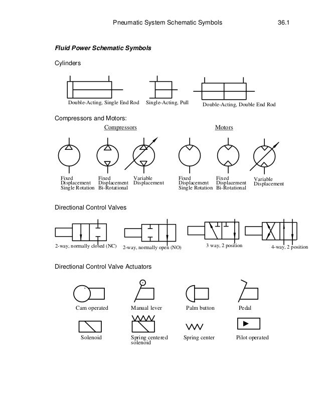
Pneumatic System SchematicSymbols 36.1
Fluid Power Schematic Symbols
Cylinders
Double-Acting, Single End Rod Double-Acting, Double End Rod
Single-Acting, Pull
Compressors and Motors:
Compressors Motors
Fixed
Displacement
Single Rotation
Fixed
Displacement
Bi-Rotational
Variable
Displacement
Fixed
Displacement
Single Rotation
Fixed
Displacement
Bi-Rotational
Variable
Displacement
Directional Control Valves
2-way, normally closed (NC) 2-way, normally open (NO) 3 way, 2 position 4-way, 2 position
Directional Control Valve Actuators
Cam operated Manual lever Palm button Pedal
Solenoid Spring centered
solenoid
Spring center Pilot operated
2.
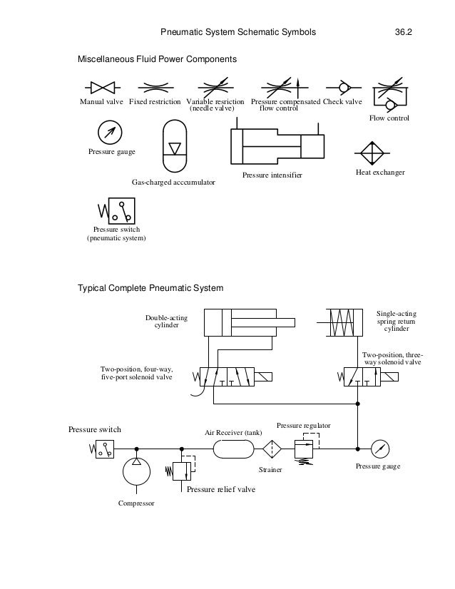
Pneumatic System SchematicSymbols 36.2
Miscellaneous Fluid Power Components
Heat exchanger
Gas-charged acccumulator
Pressure intensifier
Manual valve Fixed restriction Variable resriction
(needle valve) flow control
Pressure compensated Check valve
Flow control
Pressure gauge
Pressure switch
(pneumatic system)
Typical Complete Pneumatic System
Compressor
Air Receiver (tank)
Strainer
Pressure regulator
Pressure gauge
Single-acting
spring return
cylinder
Double-acting
cylinder
Two-position, four-way,
five-port solenoid valve
Two-position, three-
way solenoid valve
Pressure switch
Pressure relief valve