Download to read offline

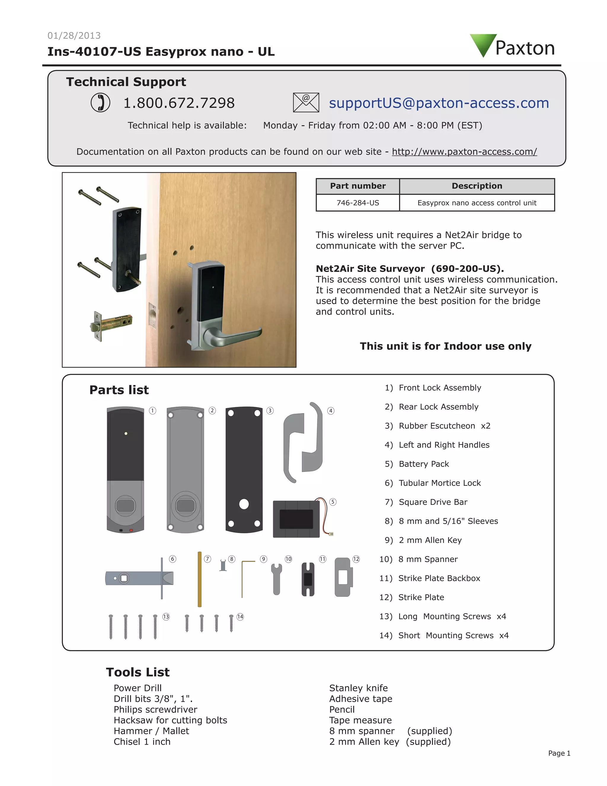
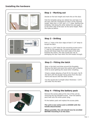
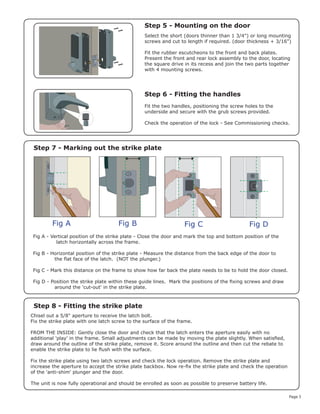
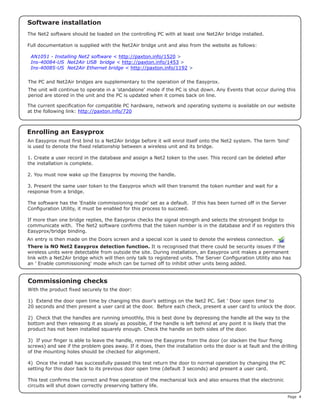

The document provides parts lists and instructions for installing an Easyprox nano access control unit. It includes a list of required tools and parts, diagrams demonstrating how to mark and drill holes in the door, and steps for mounting the lock assembly, handles, and strike plate. Technical specifications and operational details are also provided.


