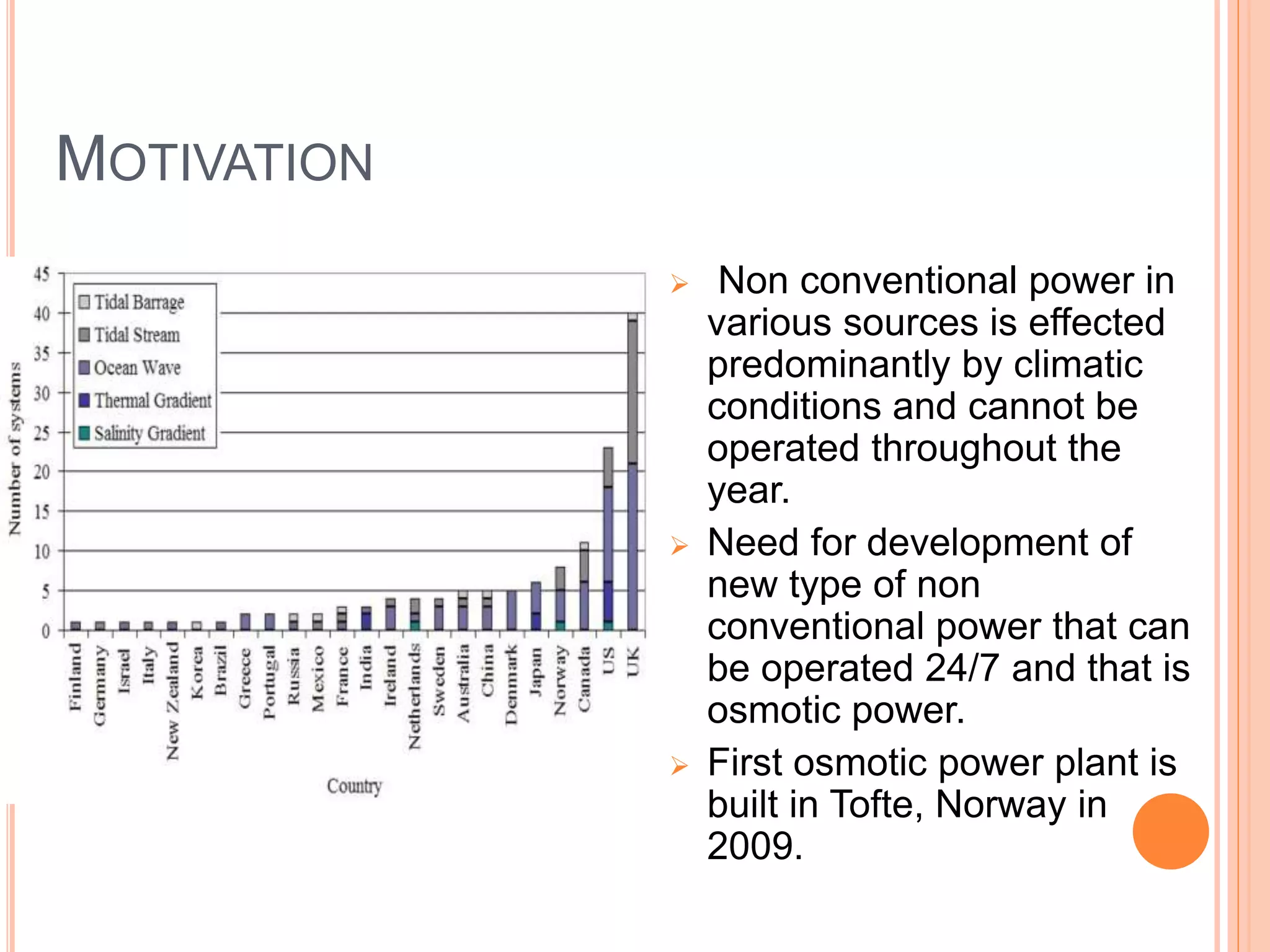
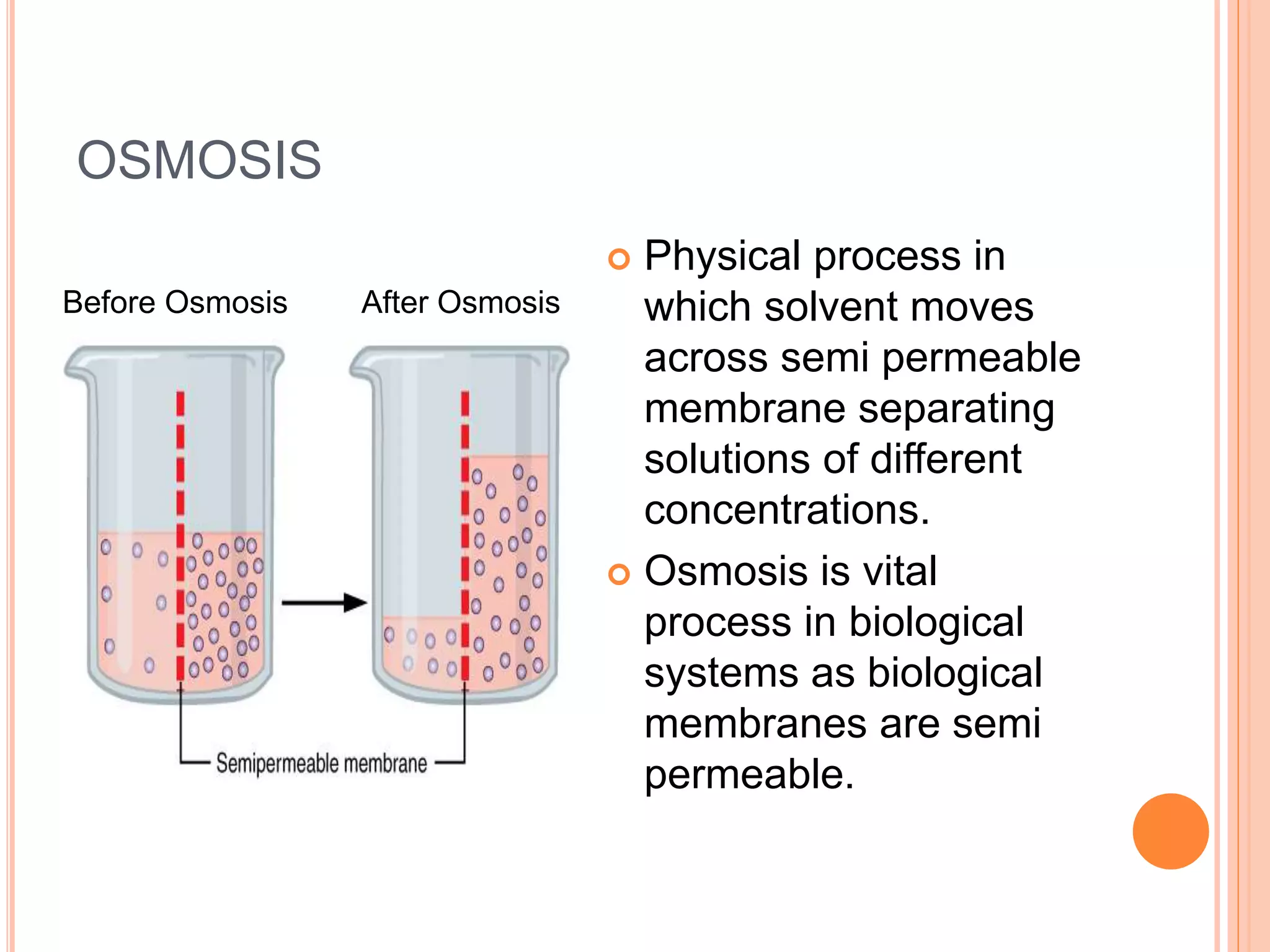
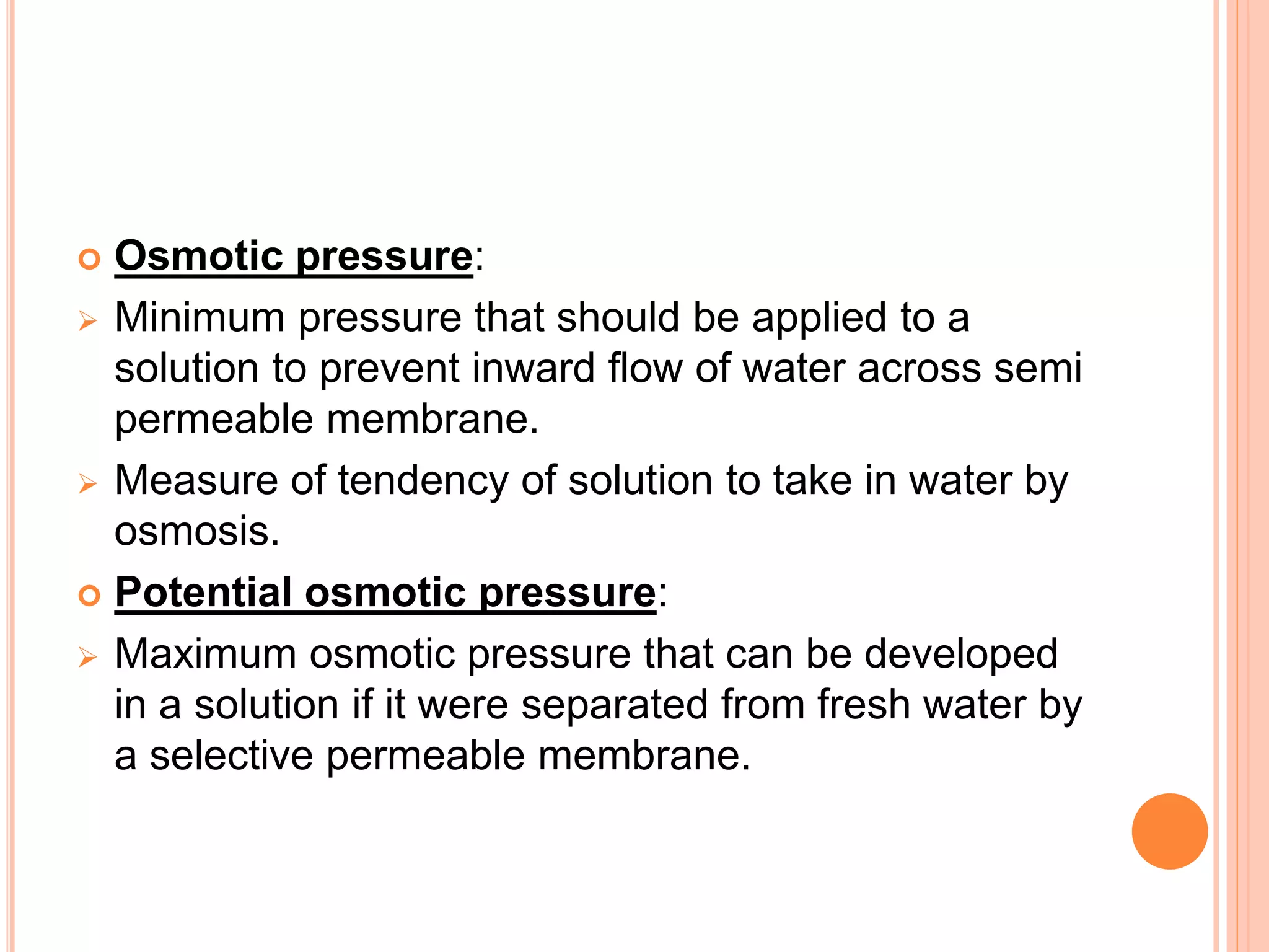
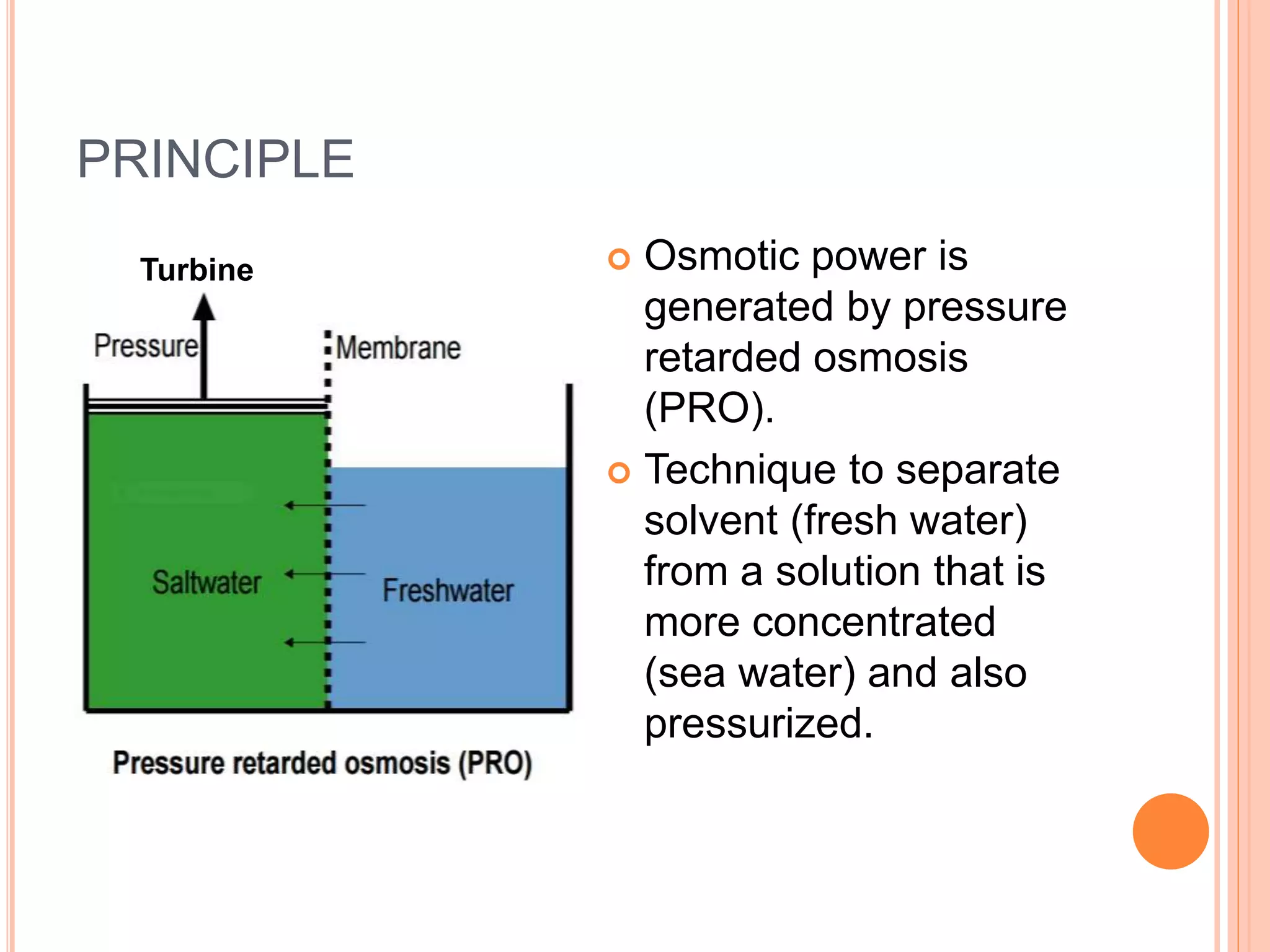
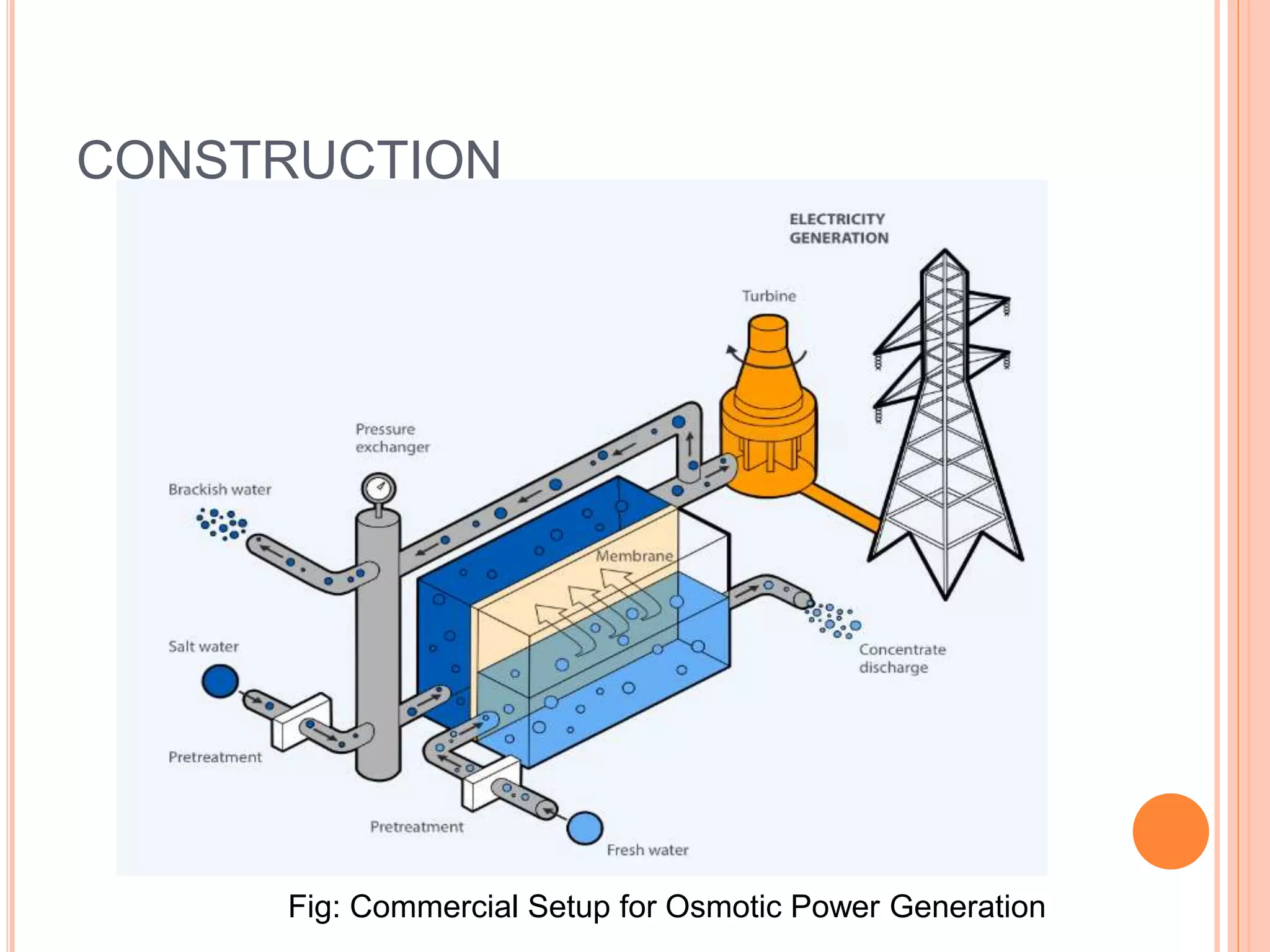
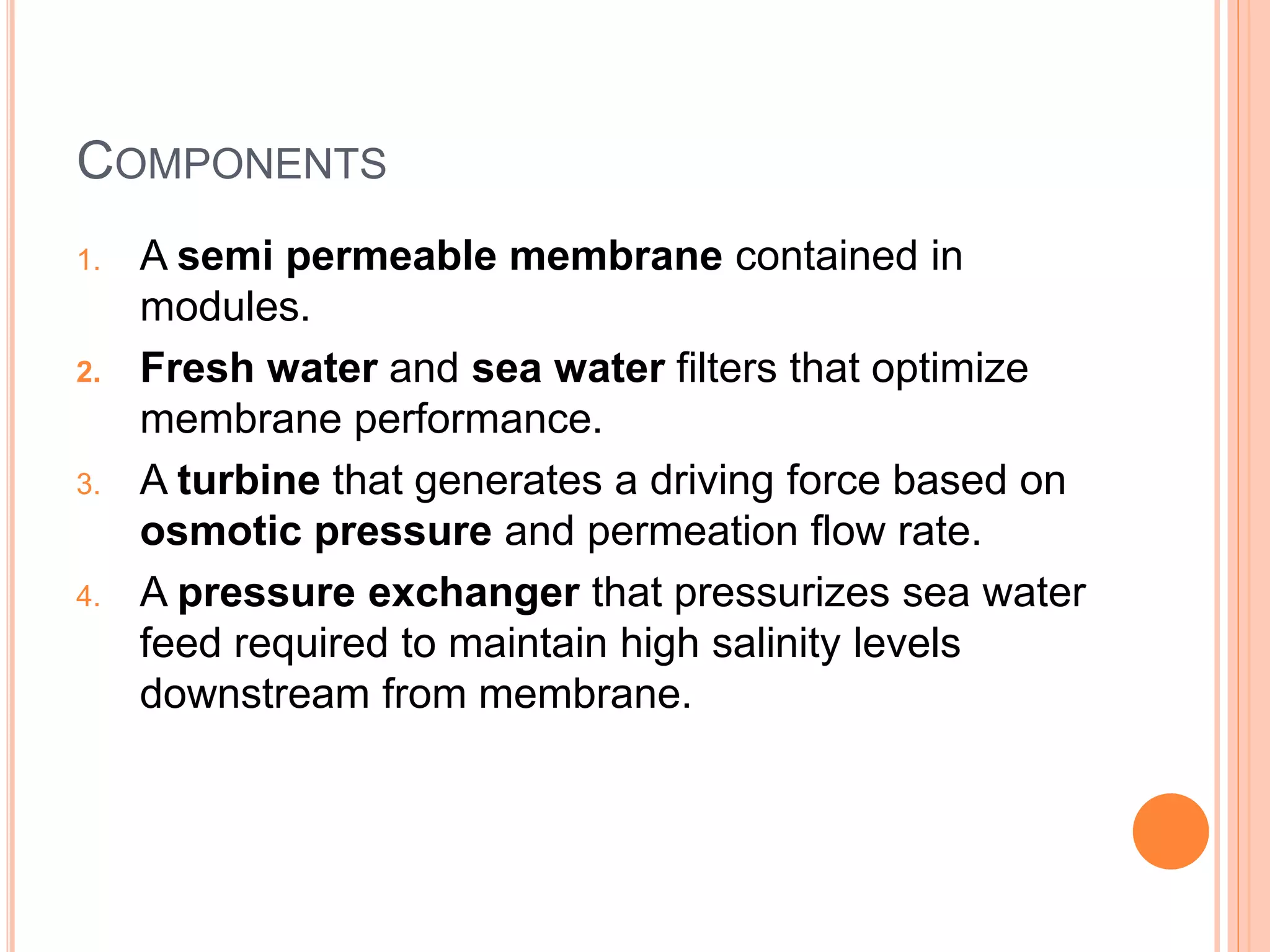
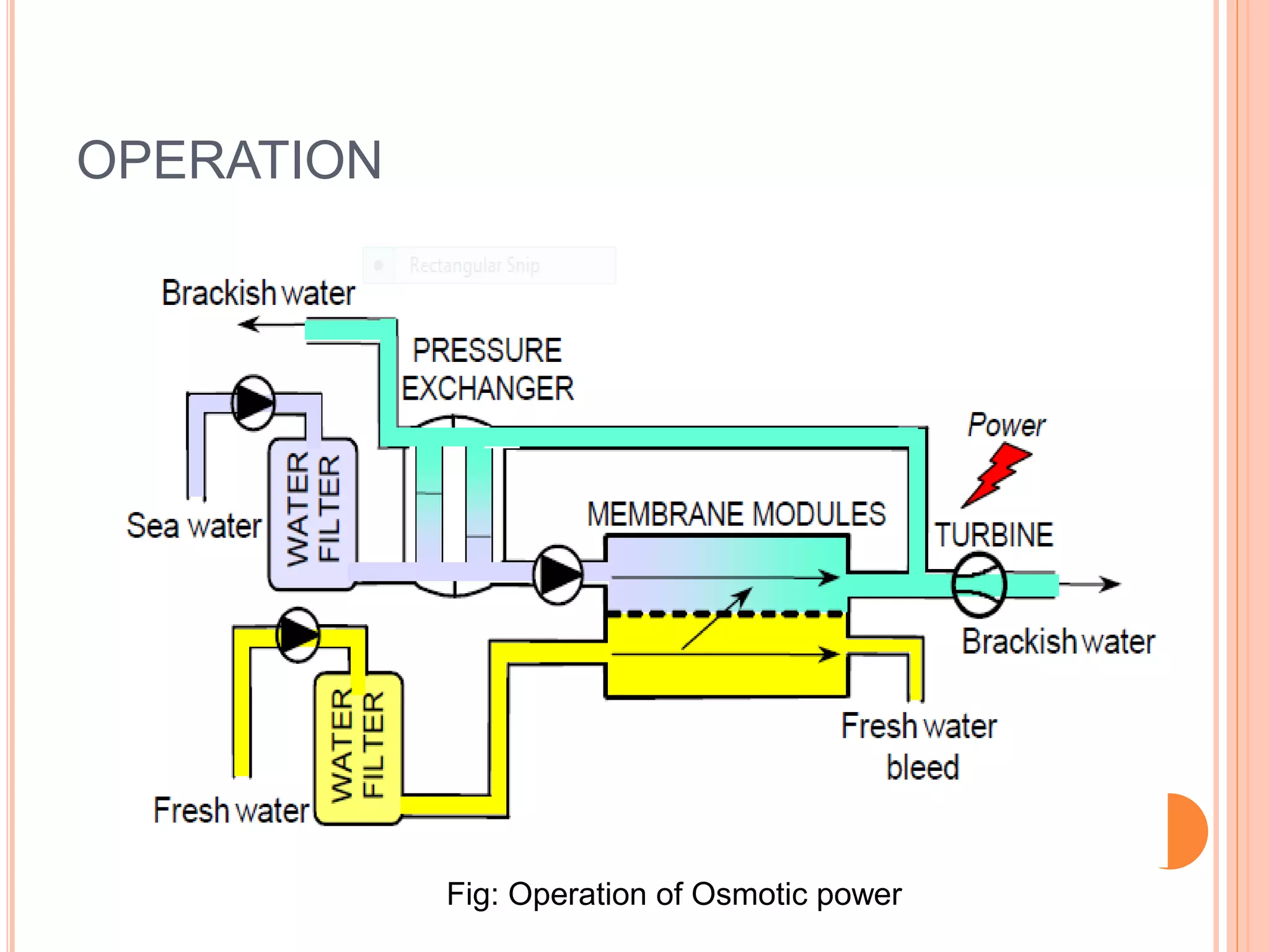
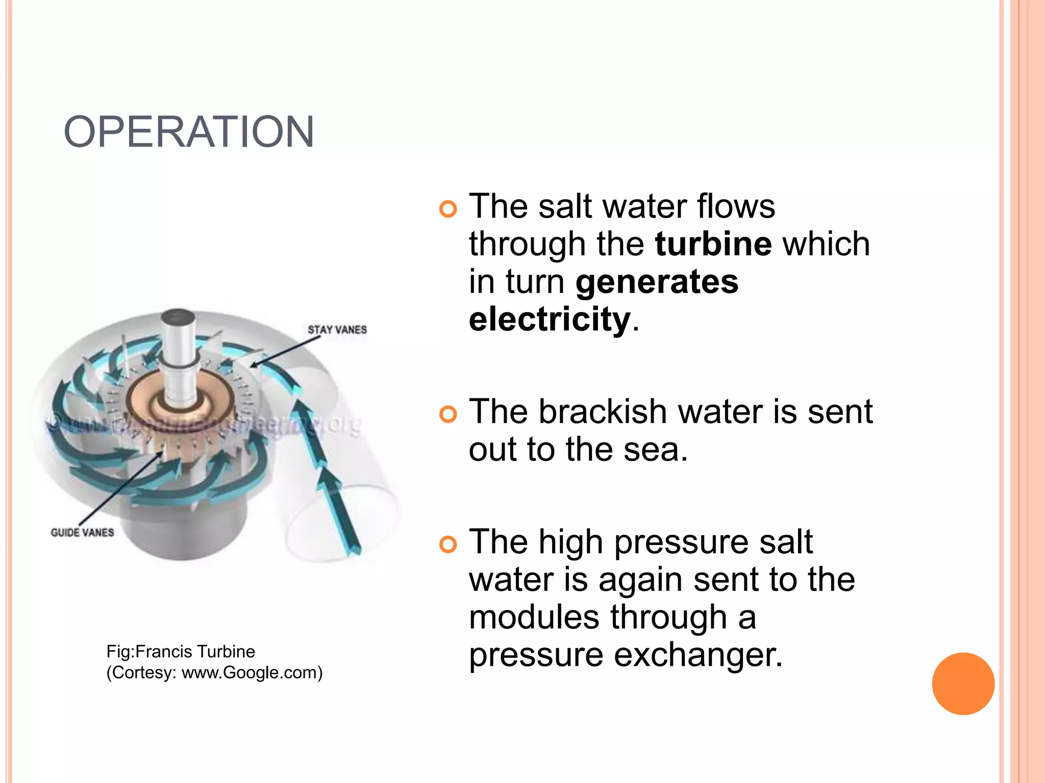
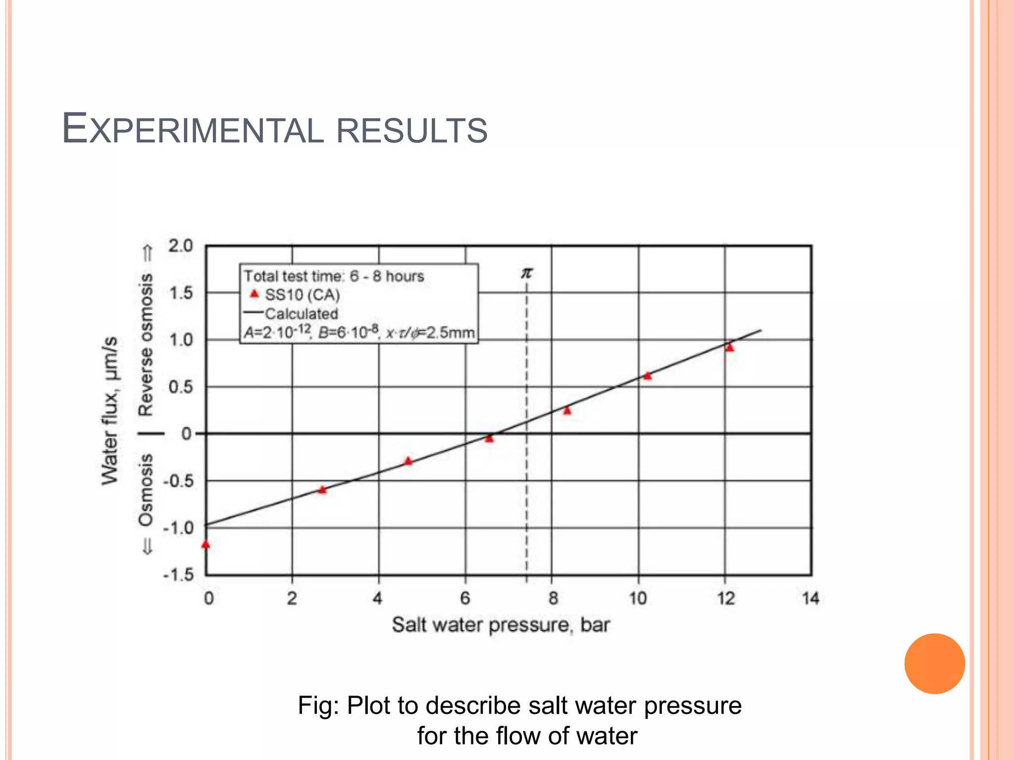
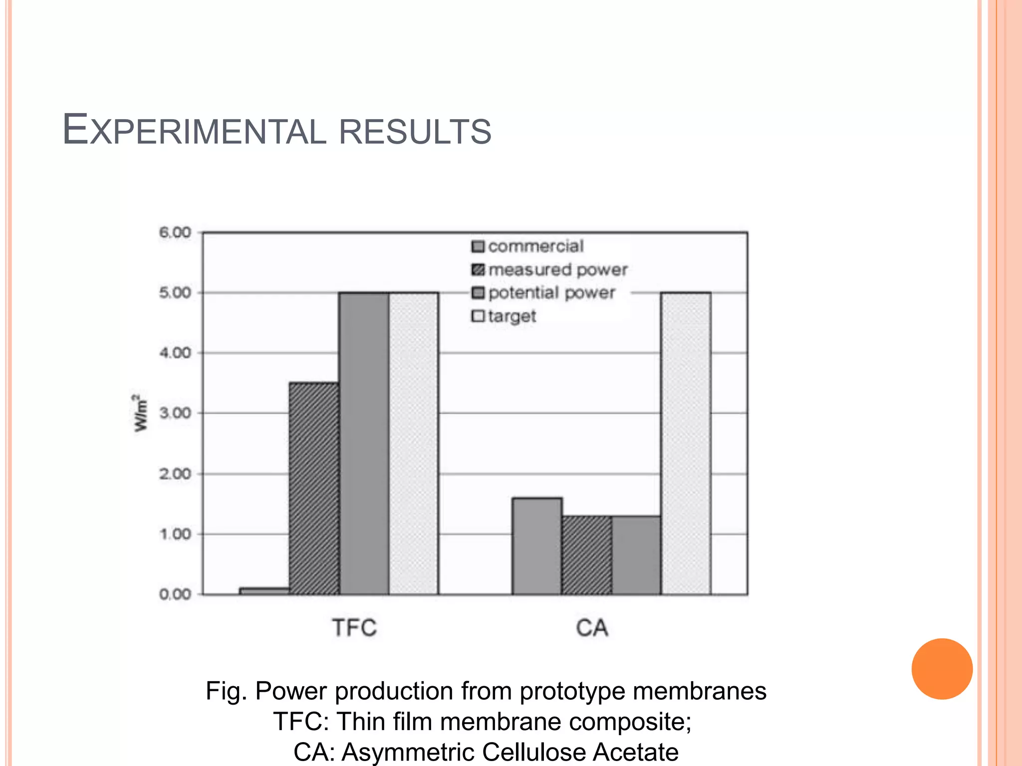
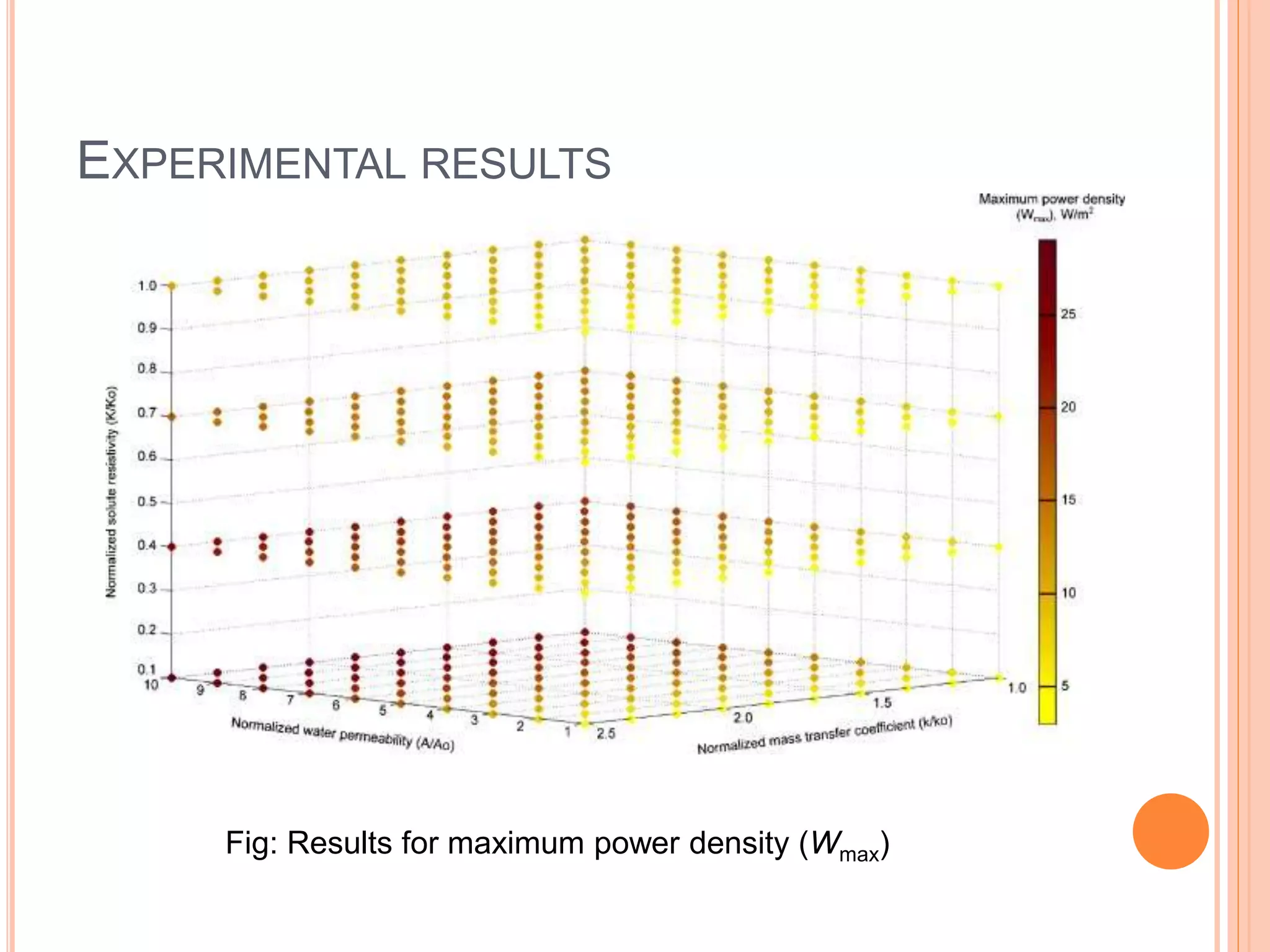
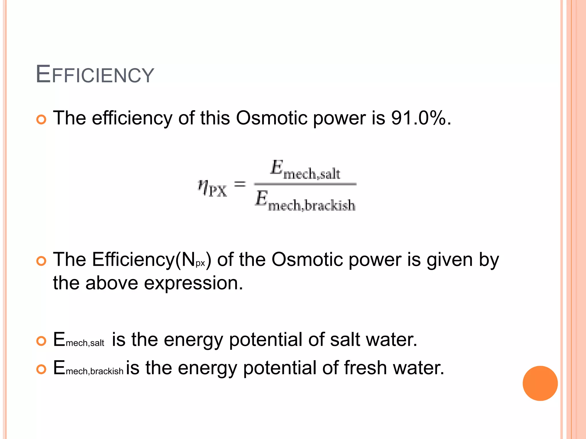
OSMOTIC POWER
Submitted By,
Snehitha Bolla(2619442)
Raja Sandeep (2660330)
OUTLINE
 Motivation
 Introduction
 Osmosis
 Osmotic power
 Principle
 Pressure retarded
osmosis (PRO)
 Construction
 Components
 Operation
 Experimental results
 Advantages
 Disadvantages
 Future scope
 Conclusion
MOTIVATION
 Non conventional power in
various sources is effected
predominantly by climatic
conditions and cannot be
operated throughout the
year.
 Need for development of
new type of non
conventional power that can
be operated 24/7 and that is
osmotic power.
 First osmotic power plant is
built in Tofte, Norway in
2009.
INTRODUCTION
 Osmotic power is energy available from difference
in salt concentration between sea water and river
water.
 It is huge and unique energy source.
 Renewable energy source that converts pressure
differential between water with high salinity and
water with lower or no salinity in to hydraulic
pressure.
 Fresh water moves by osmosis through membrane
in to sea water.
OSMOSIS
 Physical process in
which solvent moves
across semi permeable
membrane separating
solutions of different
concentrations.
 Osmosis is vital
process in biological
systems as biological
membranes are semi
permeable.
Before Osmosis After Osmosis
 Osmotic pressure:
 Minimum pressure that should be applied to a
solution to prevent inward flow of water across semi
permeable membrane.
 Measure of tendency of solution to take in water by
osmosis.
 Potential osmotic pressure:
 Maximum osmotic pressure that can be developed
in a solution if it were separated from fresh water by
a selective permeable membrane.
OSMOTIC POWER
RESULTS
Conclusion
PRINCIPLE
 Osmotic power is
generated by pressure
retarded osmosis
(PRO).
 Technique to separate
solvent (fresh water)
from a solution that is
more concentrated
(sea water) and also
pressurized.
Turbine
PRESSURE RETARDED OSMOSIS
 It relies on water molecules moving through a semi
permeable membrane.
 Semi permeable membrane allows solvent (fresh
water) to pass to the concentrated solution (sea
water) side by osmosis.
 This technique can be used to generate power from
salinity gradient energy resulting from the difference
in salt concentration between sea water and river
water.
 Output is proportional to the salinity.
CONSTRUCTION
Fig: Commercial Setup for Osmotic Power Generation
COMPONENTS
1. A semi permeable membrane contained in
modules.
2. Fresh water and sea water filters that optimize
membrane performance.
3. A turbine that generates a driving force based on
osmotic pressure and permeation flow rate.
4. A pressure exchanger that pressurizes sea water
feed required to maintain high salinity levels
downstream from membrane.
OPERATION
Fig: Operation of Osmotic power
OPERATION
 Fresh water and sea water sent into two different
modules.
 The two modules are separated by a semi-
permeable membrane.
 The Fresh water seeps through the semi-
permeable membrane to the Salt water side.
 This increases pressure on the salt water module.
OPERATION
 The salt water flows
through the turbine which
in turn generates
electricity.
 The brackish water is sent
out to the sea.
 The high pressure salt
water is again sent to the
modules through a
pressure exchanger.Fig:Francis Turbine
(Cortesy: www.Google.com)
EXPERIMENTAL RESULTS
Fig: Plot to describe salt water pressure
for the flow of water
EXPERIMENTAL RESULTS
Fig. Power production from prototype membranes
TFC: Thin film membrane composite;
CA: Asymmetric Cellulose Acetate
EXPERIMENTAL RESULTS
Fig: Results for maximum power density (Wmax)
EFFICIENCY
 The efficiency of this Osmotic power is 91.0%.
 The Efficiency(Npx) of the Osmotic power is given by
the above expression.
 Emech,salt is the energy potential of salt water.
 Emech,brackish is the energy potential of fresh water.
ADVANTAGES
 Steady, predictable output.
 Adaptable for small or large generating stations.
 Scalable or modular design (membrane modules
added as required), making it possible to increase
installed capacity.
 Generating sites near load centers, limiting power
transmission needs.
 Good potential for power plant sites.
ADVANTAGES & DISADVANTAGES
 Technology similar and complementary to that of
hydro-electric power, with osmotic power plants
able to be built on already-harnessed rivers.
 High risk of clogging and gradual degradation of
semi-permeable membranes, necessitating
pressure-filtering pretreatment of fresh water and
periodic membrane re-placement (every 5 to 7
years)
CONCLUSION
 An analysis of the PRO processes for energy
production from mixing of freshwater and seawater
has been performed at realistic conditions for
physical plant operation.
 A freshwater utilization efficiency of 40% of the
maximum mixing energy of freshwater with sea
water.
THANK YOU

Osmotic Power

  • 1.
    OSMOTIC POWER Submitted By, SnehithaBolla(2619442) Raja Sandeep (2660330)
  • 2.
    OUTLINE  Motivation  Introduction Osmosis  Osmotic power  Principle  Pressure retarded osmosis (PRO)  Construction  Components  Operation  Experimental results  Advantages  Disadvantages  Future scope  Conclusion
  • 3.
    MOTIVATION  Non conventionalpower in various sources is effected predominantly by climatic conditions and cannot be operated throughout the year.  Need for development of new type of non conventional power that can be operated 24/7 and that is osmotic power.  First osmotic power plant is built in Tofte, Norway in 2009.
  • 4.
    INTRODUCTION  Osmotic poweris energy available from difference in salt concentration between sea water and river water.  It is huge and unique energy source.  Renewable energy source that converts pressure differential between water with high salinity and water with lower or no salinity in to hydraulic pressure.  Fresh water moves by osmosis through membrane in to sea water.
  • 5.
    OSMOSIS  Physical processin which solvent moves across semi permeable membrane separating solutions of different concentrations.  Osmosis is vital process in biological systems as biological membranes are semi permeable. Before Osmosis After Osmosis
  • 6.
     Osmotic pressure: Minimum pressure that should be applied to a solution to prevent inward flow of water across semi permeable membrane.  Measure of tendency of solution to take in water by osmosis.  Potential osmotic pressure:  Maximum osmotic pressure that can be developed in a solution if it were separated from fresh water by a selective permeable membrane.
  • 7.
  • 8.
    PRINCIPLE  Osmotic poweris generated by pressure retarded osmosis (PRO).  Technique to separate solvent (fresh water) from a solution that is more concentrated (sea water) and also pressurized. Turbine
  • 9.
    PRESSURE RETARDED OSMOSIS It relies on water molecules moving through a semi permeable membrane.  Semi permeable membrane allows solvent (fresh water) to pass to the concentrated solution (sea water) side by osmosis.  This technique can be used to generate power from salinity gradient energy resulting from the difference in salt concentration between sea water and river water.  Output is proportional to the salinity.
  • 10.
    CONSTRUCTION Fig: Commercial Setupfor Osmotic Power Generation
  • 11.
    COMPONENTS 1. A semipermeable membrane contained in modules. 2. Fresh water and sea water filters that optimize membrane performance. 3. A turbine that generates a driving force based on osmotic pressure and permeation flow rate. 4. A pressure exchanger that pressurizes sea water feed required to maintain high salinity levels downstream from membrane.
  • 12.
  • 13.
    OPERATION  Fresh waterand sea water sent into two different modules.  The two modules are separated by a semi- permeable membrane.  The Fresh water seeps through the semi- permeable membrane to the Salt water side.  This increases pressure on the salt water module.
  • 14.
    OPERATION  The saltwater flows through the turbine which in turn generates electricity.  The brackish water is sent out to the sea.  The high pressure salt water is again sent to the modules through a pressure exchanger.Fig:Francis Turbine (Cortesy: www.Google.com)
  • 15.
    EXPERIMENTAL RESULTS Fig: Plotto describe salt water pressure for the flow of water
  • 16.
    EXPERIMENTAL RESULTS Fig. Powerproduction from prototype membranes TFC: Thin film membrane composite; CA: Asymmetric Cellulose Acetate
  • 17.
    EXPERIMENTAL RESULTS Fig: Resultsfor maximum power density (Wmax)
  • 18.
    EFFICIENCY  The efficiencyof this Osmotic power is 91.0%.  The Efficiency(Npx) of the Osmotic power is given by the above expression.  Emech,salt is the energy potential of salt water.  Emech,brackish is the energy potential of fresh water.
  • 19.
    ADVANTAGES  Steady, predictableoutput.  Adaptable for small or large generating stations.  Scalable or modular design (membrane modules added as required), making it possible to increase installed capacity.  Generating sites near load centers, limiting power transmission needs.  Good potential for power plant sites.
  • 20.
    ADVANTAGES & DISADVANTAGES Technology similar and complementary to that of hydro-electric power, with osmotic power plants able to be built on already-harnessed rivers.  High risk of clogging and gradual degradation of semi-permeable membranes, necessitating pressure-filtering pretreatment of fresh water and periodic membrane re-placement (every 5 to 7 years)
  • 21.
    CONCLUSION  An analysisof the PRO processes for energy production from mixing of freshwater and seawater has been performed at realistic conditions for physical plant operation.  A freshwater utilization efficiency of 40% of the maximum mixing energy of freshwater with sea water.
  • 22.