SlideShare a Scribd company logo
Optimal Control
Perspectives from the Variational Principles of Mechanics


                Ismail Hameduddin


                     Purdue University
Abstract
    Optimal control is a tremendously important (and popular) area of
research in modern control engineering. The extraordinary elegance of
optimal control results, the significance of their implications and the un-
resolved nature of their practical implementation have excited the minds
of generations of engineers and mathematicians. The sheer amount of
recent research dedicated to the topic, even after more than five decades
of the first publication of results, are a testament to this. Despite this
widespread interest, an appreciation of the philosophical origins of opti-
mal control, rooted in analytical mechanics, is still lacking. By weaving-in
analogies from the variational principles of mechanics in the wider context
of an overview of optimal control theory, this work attempts to expose the
deeper connections between optimal control and the early, philosophically
oriented results in analytical mechanics. Rather than as a dry, rigorous
exercise, this is often done through more intellectually satisfying heuristic
discussions and insights. Although the two-point boundary value problem
is given due importance (with its parallel in analytical mechanics), special
emphasis is placed on the feedback form of optimal control (Hamilton-
Jacobi-Bellman equation) since this ties in closely with the exceedingly
beautiful Hamilton-Jacobi theory. Numerical solutions to the optimal con-
trol problem and in particular, the generalized Hamilton-Jacobi-Bellman
equation with successive Galerkin approximations, are also discussed to
highlight recent trends and motivations behind optimal control research.
1    Introduction
Optimal control is the area of study that deals with choosing free parameters in
a set of differential equations such that a cost function is minimized over an evo-
lution of time. Optimal control is an extremely important field with applications
ranging from engineering, operations research to finance and economics [19, 25].
For instance, the same tool used to study dynamical systems in economic theory
was used to design the controllers on the Apollo spacecraft [15].
    Much of the development of optimal control mirrors that of analytical me-
chanics. From a philosophical point of view, optimal control is a mimicry of
nature. By the principle of least action, nature choses the motion of a system
(or particle) such as to minimize a certain form of “energy”. Then from the
point of view of nature, it “uses optimal control” to minimize the energy used
by systems in their motion. Optimal control is simply the turning of the tables
so that this tool is available in controlling the behavior of dynamical systems in
an optimal manner (with respect to a cost) subject to the (dynamic) constraints
already imposed by nature.
    This report introduces the ideas of optimal control to an audience familiar
with analytical mechanics and variational principles. The intent is to provide a
basic understanding of the fundamental results and then delve into some more
advanced/recent results. The report can also be seen broadly in a chronological
manner: It starts with a short review of some basic results calculus of varia-
tions (1700-1900), then proceeds to optimal control theory (1950-1970), which
is followed by a discussion of the generalized Hamilton-Jacobi-Bellman equation
(1979) and finally, the paper is capped off by a discussion of a numerical scheme
developed in the 1990’s.
    An effort has been made in the presentation to make the material relevant
and intellectually stimulating by establishing connections between classical an-
alytical mechanics and optimal control.


2    History
Optimal control is an outgrowth of the variational principles of mechanics and
it is difficult to pinpoint exactly when a transition was made from examining
systems moving freely under their own influence to determining a reference
control for a system to achieve a certain objective while minimizing a cost
function. A popular choice is the formulation of the brachistochrone problem:
     Given two fixed points in a vertical plane, let a particle start from
     rest at the higher point and travel to the lower point under its own
     weight in a uniform gravity field. What path or curve must the
     particle follow in order to reach the second point in the shortest
     amount of time?
An obvious solution to the minimum length problem is the straight line between
both points. However, the straight line does not minimize the amount of time.


                                        3
The correct solution is a cycloid between the two points A and B. This problem
was first proposed by Galileo in 1638 in his book Two New Science. Galileo
accompanied the problem with an incorrect solution based on the geometry of
the problem. Instead of a cycloid, he suggested a circle through the two points
and center located a certain distance away (on an axis) [26, 28].
   Nearly sixty years later, oblivious to Galileo’s introduction of the problem,
Johann Bernoulli proposed the following “challenge” in the June 1696 issue of
Acta Eruditorum [28]:
      If in a vertical plane two points A and B are given, then it is required
      to specify the orbit AM B of the moveable point M , along which it,
      starting from A, and under the influence of its own weight, arrives at
      B in the shortest possible time. So that those who are keen of such
      matters will be tempted to solve this problem, is it good to know that
      it is not, as it may seem, purely speculative and without practical
      use. Rather it even appears, and this may be hard to believe, that
      it is very useful also for other branches of science than mechanics
      In order to avoid a hasty conclusion, it should be remarked that
      the straight line is certainly the line of shortest distance between A
      and B, but it is not the one which is travelled in the shortest time.
      However, the curve AM B - which I shall divulge if by the end of this
      year nobody else has found it - is very well known among geometers.

This problem is precisely a minimum-time optimal control problem. Five math-
ematicians solved the brachistochrone problem including Johan Bernoulli him-
self, Leibniz, de l’Hopital, Jakob Bernoulli (Johan’s brother) and Isaac Newton.
Jakob Bernoulli formulated a more difficult version of the brachistochrone prob-
lem and solved it using a different type of proof. Jakob Bernoulli was mocked
by his brother [28, 26] for using a sloppy proof but that proof formed the foun-
dation of the future calculus of variations and the work of Lagrange, Hamilton
and Jacobi.
    From the brachisochrone problem to the development of control, the history
of optimal control closely parallels that of analytical mechanics (variational prin-
ciples of mechanics). Kalman’s work in introducing the state-space architecture
to control revolutionized developments and reopened the door for significant
developments in optimal control [18].
    Two schools of optimal control developed during the 1950’s and 1960’s. The
first was led by Richard E. Bellman and was centered in the USA. Bellman was
a mathematician and worked as a research scientist at The RAND Corporation
in Santa Monica, California [7]. His research was focused on optimizing the
control of multistage (discrete) systems [4, 6]. Two years after joining RAND
from Princeton, Bellman published his first book “The Theory of Dynamic Pro-
gramming” [5]. His development led to the Bellman equation which provides
sufficient conditions for optimality. Later this was generalized to continous-time
systems where it bore a striking similarity to the Hamilton-Jacobi equation of
analytical mechanics. In fact, both equations derive from the same principle


                                         4
of minimizing an (integral) performance index subject to nonholonomic con-
straints. Thus, the continous-time version of the Bellman equation is known as
the Hamilton-Jacobi-Bellman equation [8]. The derivations in this paper will
focus on the Hamilton-Jacobi-Bellman formulation.
    The other school of optimal control was centered in the USSR and led by the
acclaimed Soviet mathematician Lev Semenovich Pontryagin. Pontryagin devel-
oped his famous maximum principle at around roughly the same time as Bell-
man [22] but his work was, until later, available only in Russian [23]. Pontryagin
approach the problem of optimal control from the more classical approach of
the calculus of variations. The famous Pontryagin’s minimum principle gener-
alized necessary conditions for optimality and it was shown that the standard
Euler-Lagrange equations are simply a special case of this principle [8].
    Ever since these theoretical foundations were laid in optimal control, much of
the development has been focused on applications and numerical techniques [18].
Even half a century after the solution of the optimal control problem was first
formulated, efficient numerical methods for the computation of these solutions
are still an active area of research. In general, the problem remains unresolved
since there is no efficient numerical scheme applicable in all cases even with the
exponentially larger computational resources available today versus five decades
ago.


3    The Optimal Control Problem
Consider a nonlinear time-varying dynamical system described by the equations

                ˙
                x(t) = f (x(t), u(t), t);            x(t0 );    t0 ≤ t ≤ tf     (1)

where x(t) ∈ Rn is the vector of internal states and u(t) ∈ Rm is the vector
of control input. Suppose we are given an objective to drive the dynamical
system from some initial state x(t0 ) at initial time t = t0 to some specified final
state x(tf ) at final time t = tf given freedom over the assigned control input
u(t). In general, there are an infinite number of u(t) that satisfy this objective.
The goal of optimal control is to determine a u(t) that not only achieves the
objective but is also optimal with respect to a specified performance index or
cost. The performance index is chosen by the designer and therefore, the optimal
control u∗ (t) is not optimal in the universal sense but only with respect to the
performance index.
    A general performance index is given by
                                                tf
                    J = φ(x(tf ), tf ) +             L(x(t), u(t), t) dt        (2)
                                            t0

where the L(x(t), u(t), t) is the weighting function and φ(x(tf ), tf ) is the final-
state weighting function. The final-state weighting function is a function that
we desire to minimize at the final state. An example of this might be the final
energy. The weighting function, on the other hand, is a function that we desire


                                            5
to minimize throughout the time interval [t0 , tf ]. The weighting function is
commonly a function of the control input u(t). This is because we often want to
minimize the control “effort” expended to achieve the control objective. During
the reorientation of a spacecraft, for example, minimizing the control input u(t)
over the entire interval reduces the amount of valuable fuel consumed.
    The control objective may be stated not only directly in terms of the final
state x(tf ) but may be function of the final state and time. This function is
called the final state constraint and is given by

                                 Ψ(x(tf ), tf ) = 0                              (3)

where Ψ ∈ Rp . From henceforth Ψ(x(tf ), tf ) will be treated as the control ob-
jective. Since this is a control objective, it differs from the final-state weighting
function φ(x(tf ), tf ) in that φ(x(tf ), tf ) only needs to be minimized at the final
time while Ψ(x(tf ), tf ) = 0 is a strict condition that must be met by the control
input u(tf ) at the final time.
    The optimal control problem maybe pictured to be the problem of finding an
optimal path from an initial point to a final surface described by Ψ(x(tf ), tf ) =
0. Consider the case where we have x ∈ R2 . The optimal control problem is
then to find an optimal path from a point in R3 , i.e. (x(t0 ), t0 ), to the family of
points satisfying Ψ(x(tf ), tf ) = 0. Now if we have a fixed final time and fixed
end state, this family points is restricted to a single point. Otherwise, if the
final time is fixed but the final states are a function, we have a line. If we have
a free final time (as in a minimum time problem) and final states as a function,
we have a surface. This type of visualization is handy tool when dealing with
optimal control problems.
    The next section begins a discussion of a basic result from the calculus of
variations. This is then used to develop a solution to the optimal control problem
presented here.


4    Variation with Auxiliary Conditions
It is instructive to first consider the problem of minimizing an integral
                                      tf
                               I=                ˙
                                           F (q, q, t) dt                        (4)
                                     t0

where q ∈ Rn , subject to the constraints

                                    φ(q, t) = 0.                                 (5)

where φ ∈ Rm . What will follow is a derivation from the calculus variations.
The parallels with optimal control will become clear in the next section.
    For an unconstrained problem, it is sufficient that the integral (4) be station-
ary, i.e., the variation of I vanish, for the minimum, assuming that the second


                                            6
variation ensures a minimum (this is not required for problems of dynamics).
Thus, we require
                                            tf
                          δI = δ                       ˙
                                                 F (q, q, t) dt = 0.          (6)
                                           t0

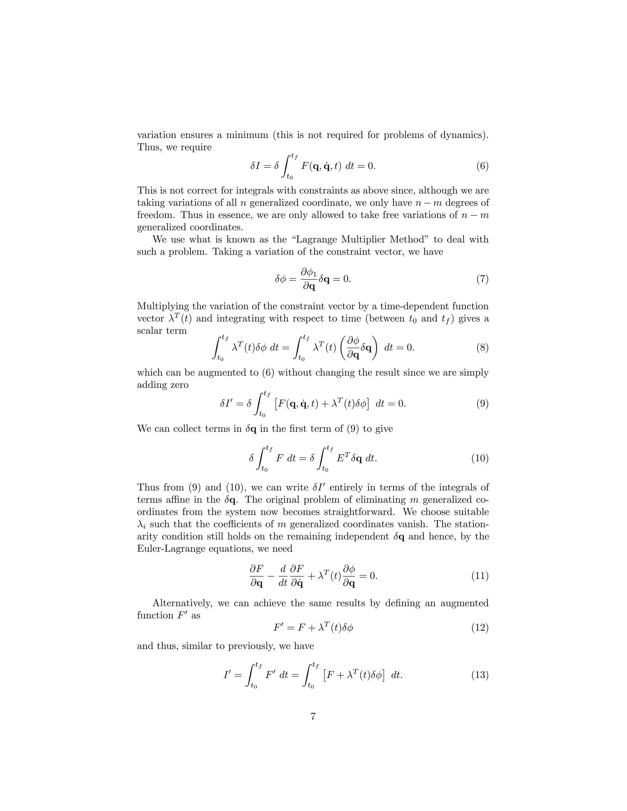
This is not correct for integrals with constraints as above since, although we are
taking variations of all n generalized coordinate, we only have n − m degrees of
freedom. Thus in essence, we are only allowed to take free variations of n − m
generalized coordinates.
    We use what is known as the “Lagrange Multiplier Method” to deal with
such a problem. Taking a variation of the constraint vector, we have
                                                 ∂φ1
                                         δφ =        δq = 0.                  (7)
                                                 ∂q
Multiplying the variation of the constraint vector by a time-dependent function
vector λT (t) and integrating with respect to time (between t0 and tf ) gives a
scalar term
                   tf                 tf
                                                ∂φ
                      λT (t)δφ dt =      λT (t)    δq dt = 0.               (8)
                  t0                 t0         ∂q
which can be augmented to (6) without changing the result since we are simply
adding zero
                                   tf
                   δI = δ                F (q, q, t) + λT (t)δφ dt = 0.
                                               ˙                              (9)
                               t0

We can collect terms in δq in the first term of (9) to give
                                    tf                   tf
                          δ              F dt = δ             E T δq dt.     (10)
                               t0                       t0

Thus from (9) and (10), we can write δI entirely in terms of the integrals of
terms affine in the δq. The original problem of eliminating m generalized co-
ordinates from the system now becomes straightforward. We choose suitable
λi such that the coefficients of m generalized coordinates vanish. The station-
arity condition still holds on the remaining independent δq and hence, by the
Euler-Lagrange equations, we need
                          ∂F   d ∂F            ∂φ
                             −        + λT (t)    = 0.                       (11)
                          ∂q        ˙
                               dt ∂ q          ∂q
   Alternatively, we can achieve the same results by defining an augmented
function F as
                             F = F + λT (t)δφ                        (12)
and thus, similar to previously, we have
                              tf                   tf
                    I =            F dt =                F + λT (t)δφ dt.    (13)
                          t0                      t0


                                                   7
Setting δI = 0 with an appropriate λ(t) recovers the results (11).
   For nonholonomic constraints
                                         dφ = aT dq = 0.                                 (14)
the result (11) still holds except that the partial derivatives ∂φ/∂q are replaced
by the coefficient a of the nonholonomic constraint vector, (14). We thus have
                                   ∂F   d ∂F
                                      −        + λT (t)a.                                (15)
                                   ∂q        ˙
                                        dt ∂ q
A similar result for the optimal control problem using the same methods for
derivation is shown in the next section.


5     Optimal Control by the Euler-Lagrange Method
The approach of optimal control is to treat the problem of finding the optimal
control u(t) as one of finding the stationary value of the performance index
subject to nonholonomic constraints which are precisely the system dynamics.
In this philosophy, we are, in effect, turning the problem upside down. Rather
than approaching the system dynamics first and then finding a control that
would minimize a performance index, we approach the performance index first
and treat the system dynamics as auxiliary constraints on the system. It is this
simple, yet groundbreaking, change of perspective that spurred on the decades
of research and produced some of the most significant results of the past half
century. After this perspective change, the problem can be solved almost iden-
tically as in the previous section.
    Consider first the case when there is no final state constraint but we have
fixed initial and final time. Begin by rearranging the system dynamics (1),
multiplying by an undetermined time-dependent vector λT (t) and integrating
between the limits to give
                        tf
                             λT (t) [f (x(t), u(t), t) − x(t)] dt = 0.
                                                         ˙                               (16)
                     t0

We can then augment the performance index (2) with (16) without any impact
since we are simply adding zero, similar to what we did in the general Lagrange
multiplier method
                             tf
 J = φ(x(tf ), tf ) +             L(x(t), u(t), t) + λT (t) [f (x(t), u(t), t) − x(t)]
                                                                                 ˙       dt.
                          t0
                                                                                         (17)
    As in analytical mechanics, define the Hamiltonian function as
           H(x(t), u(t), λ(t), t) = L(x, u(t), t) + λT (t)f (x(t), u(t), t)              (18)
which substituting in (17) yields
                                     tf
         J = φ(x(tf ), tf ) +             H(x(t), u(t), λ(t), t) − λT (t)x(t) dt.
                                                                         ˙               (19)
                                    t0


                                               8
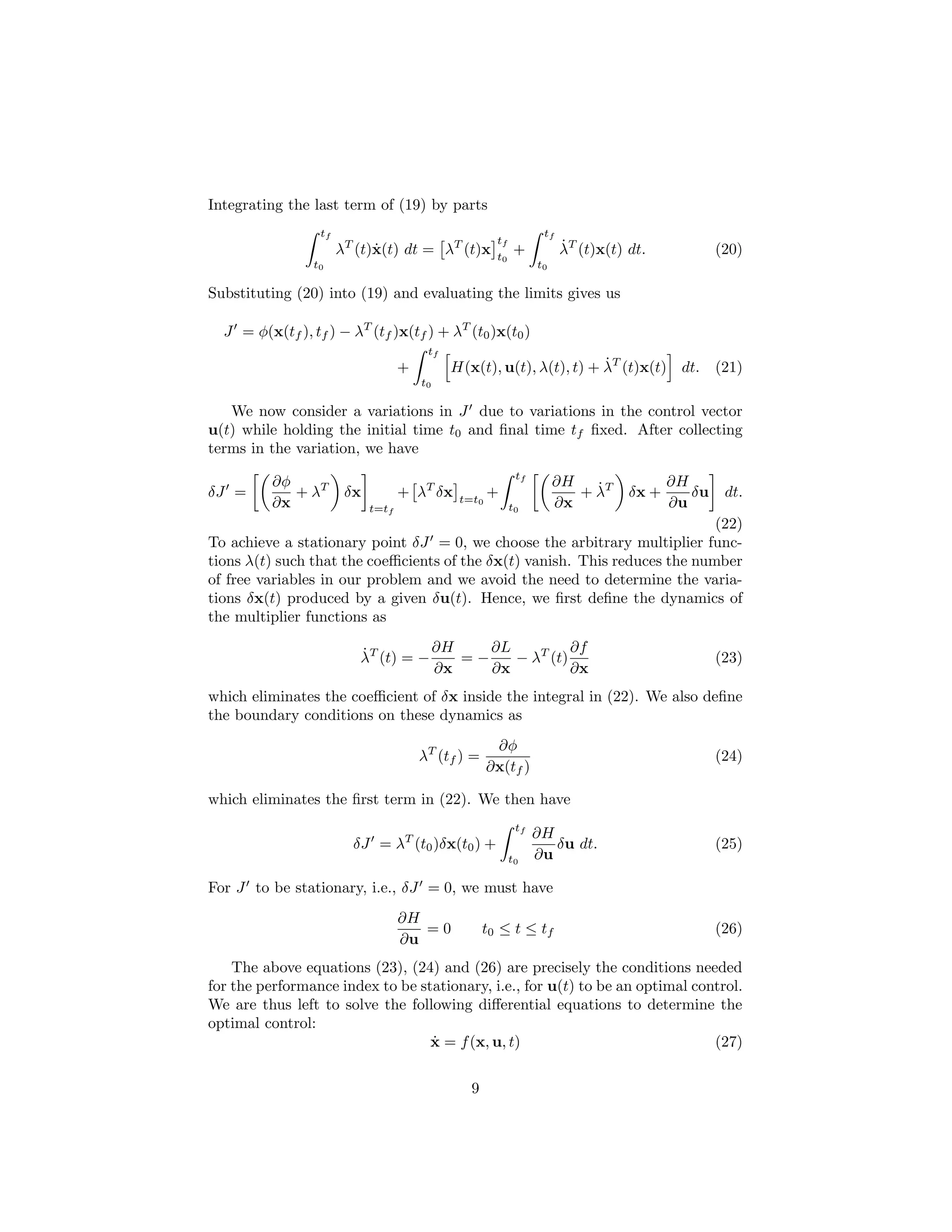
Integrating the last term of (19) by parts
                  tf                                               tf
                                                       tf
                       λT (t)x(t) dt = λT (t)x
                             ˙                              +           ˙
                                                                        λT (t)x(t) dt.            (20)
                                                       t0
                 t0                                               t0

Substituting (20) into (19) and evaluating the limits gives us

  J = φ(x(tf ), tf ) − λT (tf )x(tf ) + λT (t0 )x(t0 )
                                         tf
                                    +                                  ˙
                                              H(x(t), u(t), λ(t), t) + λT (t)x(t) dt. (21)
                                        t0

   We now consider a variations in J due to variations in the control vector
u(t) while holding the initial time t0 and final time tf fixed. After collecting
terms in the variation, we have
                                                             tf
          ∂φ                                                           ∂H   ˙             ∂H
δJ =         + λT       δx          + λT δx    t=t0
                                                      +                   + λT     δx +      δu    dt.
          ∂x                 t=tf                           t0         ∂x                 ∂u
                                                                             (22)
To achieve a stationary point δJ = 0, we choose the arbitrary multiplier func-
tions λ(t) such that the coefficients of the δx(t) vanish. This reduces the number
of free variables in our problem and we avoid the need to determine the varia-
tions δx(t) produced by a given δu(t). Hence, we first define the dynamics of
the multiplier functions as

                          ˙          ∂H    ∂L          ∂f
                          λT (t) = −    =−    − λT (t)                                            (23)
                                     ∂x    ∂x          ∂x
which eliminates the coefficient of δx inside the integral in (22). We also define
the boundary conditions on these dynamics as
                                                       ∂φ
                                        λT (tf ) =                                                (24)
                                                      ∂x(tf )

which eliminates the first term in (22). We then have
                                                             tf
                                                                  ∂H
                         δJ = λT (t0 )δx(t0 ) +                      δu dt.                       (25)
                                                            t0    ∂u

For J to be stationary, i.e., δJ = 0, we must have
                                    ∂H
                                       =0            t0 ≤ t ≤ tf                                  (26)
                                    ∂u
    The above equations (23), (24) and (26) are precisely the conditions needed
for the performance index to be stationary, i.e., for u(t) to be an optimal control.
We are thus left to solve the following differential equations to determine the
optimal control:
                                  ˙
                                  x = f (x, u, t)                              (27)


                                                 9
T                  T
                           ˙          ∂f                  ∂L
                           λ=−                  λ−                 =0                (28)
                                      ∂x                  ∂x
where u(t) is determined by
                                       T                   T
                                 ∂f                  ∂L
                                           λ+                  =0                    (29)
                                 ∂u                  ∂u

and the boundary conditions are

                                            x(t0 )                                   (30)
                                                          T
                                                     ∂φ
                                    λ(tf ) =                                         (31)
                                                     ∂x
    The equations (27) through (31) parallel the Euler-Lagrange equations from
standard variational calculus and are referred to as the stationarity conditions.
Notice the similarity between (11) and (28),(29).
    The multiplier vector elements λ are known as the “costates” because the
                                                              ˙
optimal control is determined by solving the state dynamics x together with the
multiplier dynamics λ.˙
    Since the boundary conditions are specified at both initial and final time, the
problem itself is often called the two-point boundary-value problem (2PBVP).
We are required to specify both the initial and final time for such a problem.
This restriction (of specifying both initial and final time) is overcome later by
using another method of solution of the optimal control problem that utilizes
elements from Hamilton-Jacobi theory.
    An assumption of no final state constraint was assumed in the derivation
of the previous stationarity conditions. This is not true in many cases. The
problem where a final state vector

                                    Ψ(x(tf ), tf ) = 0                               (32)

is specified is dealt with below.
    Analagous to the previous treatment, we form a performance index that is
augmented by a multiple of the final state constraint vector with the effect of
adding a multiple of zero

  J = φ(x(tf ), tf ) + ν T Ψ(x(tf ), tf )
                     tf
                          L(x(t), u(t), t) + λT (t) [f (x(t), u(t), t) − x(t)]
                                                                         ˙       dt. (33)
                    t0

where ν T is a vector of undetermined multipliers. The previous derivation may
be repeated if we define
                                 Φ = φ + νT Ψ                              (34)


                                                10
and substitute into the performance index except that the ν T will not be spec-
ified. This can be resolved with some incremental effort, and the previous
stationarity conditions can be shown to hold with a minor modification to (31)

                                       ∂φ      ∂ψ
                          λ(tf ) =        + νT                 .             (35)
                                       ∂x      ∂x       t=tf

This completes our discussion of optimal control by the Euler-Lagrange method.
Although, many further extensions to the current results exists, they are not
treated in this report.
    Another approach to solving the optimal control problem is to use paral-
lels from the theory of Hamilton-Jacobi from analytical mechanics. Thus, a
short review of the Hamilton-Jacobi theory is given in the next section with an
emphasis on parts of the theory that prove useful in optimal control.


6    Hamilton-Jacobi Theory
Hamilton’s problem deals with solving for the motion of a dynamic system such
that its generalized coordinates are reduced to quadratures. According to the
principle of least action, the motion of a dynamic system or the solution of
Hamilton;s problem is such that it minimizes the total energy or “action”. By
Hamilton’s principle, this “action” is the canonical integral. Thus achieving a
stationary point on the canonical integral implies that a minimum energy motion
has been achieved and Hamilton’s problem has been solved. The stationary
point is not verified via a second variation because in general, for problems
in dynamics, a stationary point cannot imply a maximum (since the feasible
generalized coordinates are theoretically unbounded). Only a basic discussion
of this problem and its solution will be presented in this section as a complete
derivation is beyond the scope of the report. The reader is referred to references
[16, 13, 21] for more details.
    The canonical integral in analytical mechanics is given by
                           tf
                     I=              ˙                 ˙
                                L(q, q, t) dt = I(q0 , q0 , t0 , tf )        (36)
                          t0

where L is the Lagrangian, q is the generalized coordinate vector, q is the˙
                                      ˙
generalized velocity vector and q0 , q0 are the vectors of initial conditions. For
a stationary point, the first variation of the canonical integral must be zero

                                        δI = 0.                              (37)

A motion that satisfies such a condition is achieved in the Hamilton-Jacobi the-
ory via a canonical transformation, i.e., a transformation that does not violate
Hamilton’s principle in the dynamics of the system.
   The statement of (36) is that the canonical integral, including integration
constants, is fully determined once we have the initial generalized coordinates


                                           11
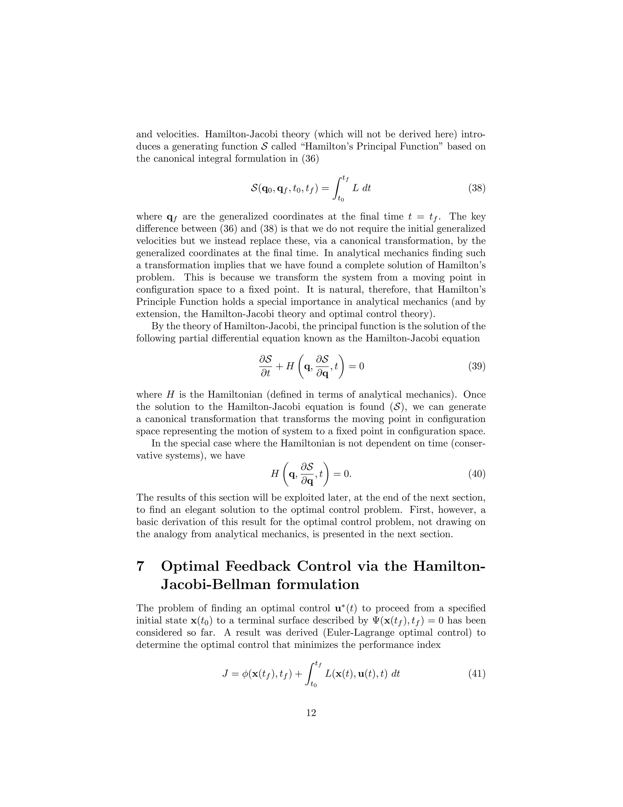
and velocities. Hamilton-Jacobi theory (which will not be derived here) intro-
duces a generating function S called “Hamilton’s Principal Function” based on
the canonical integral formulation in (36)
                                                      tf
                           S(q0 , qf , t0 , tf ) =         L dt                (38)
                                                     t0

where qf are the generalized coordinates at the final time t = tf . The key
difference between (36) and (38) is that we do not require the initial generalized
velocities but we instead replace these, via a canonical transformation, by the
generalized coordinates at the final time. In analytical mechanics finding such
a transformation implies that we have found a complete solution of Hamilton’s
problem. This is because we transform the system from a moving point in
configuration space to a fixed point. It is natural, therefore, that Hamilton’s
Principle Function holds a special importance in analytical mechanics (and by
extension, the Hamilton-Jacobi theory and optimal control theory).
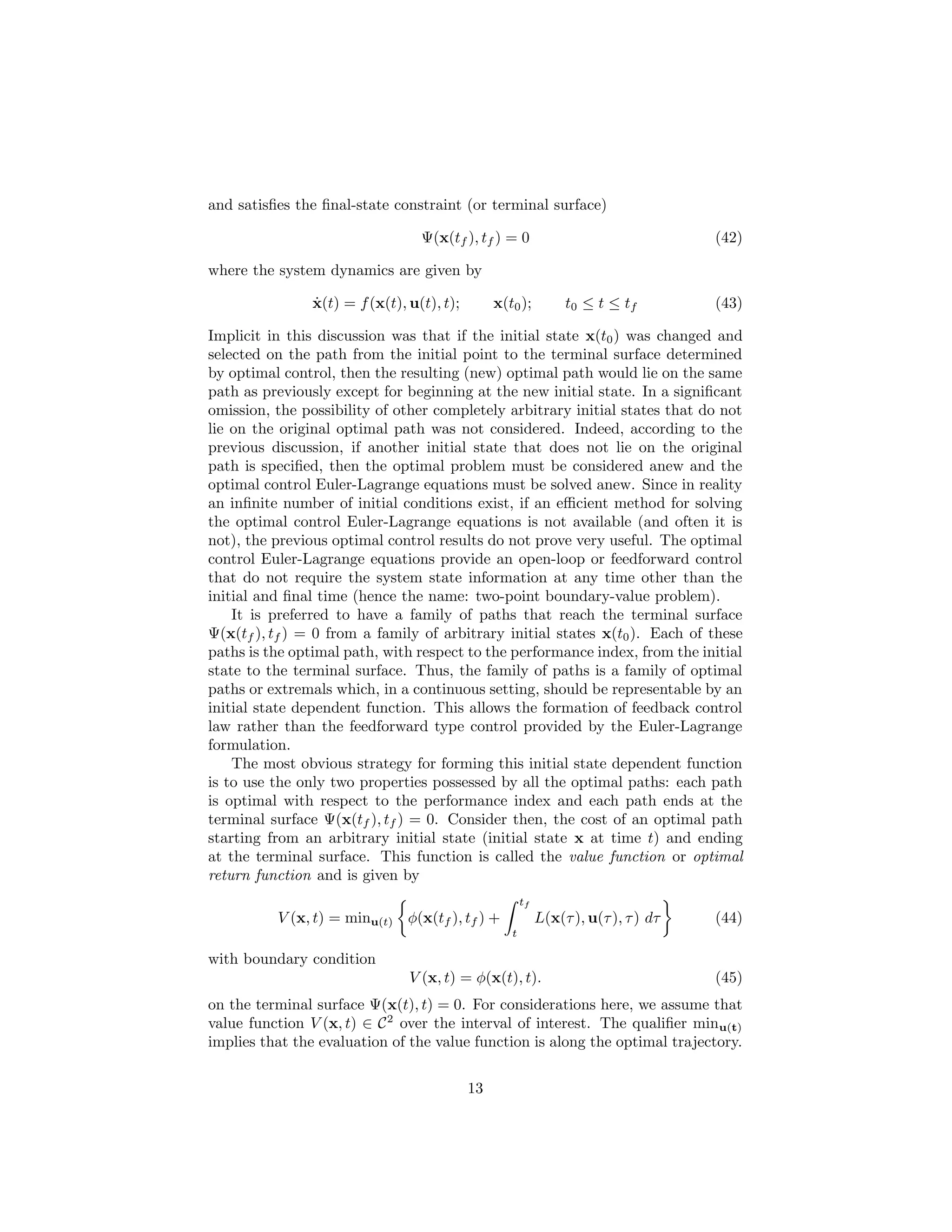
    By the theory of Hamilton-Jacobi, the principal function is the solution of the
following partial differential equation known as the Hamilton-Jacobi equation

                             ∂S        ∂S
                                + H q,    ,t              =0                   (39)
                             ∂t        ∂q

where H is the Hamiltonian (defined in terms of analytical mechanics). Once
the solution to the Hamilton-Jacobi equation is found (S), we can generate
a canonical transformation that transforms the moving point in configuration
space representing the motion of system to a fixed point in configuration space.
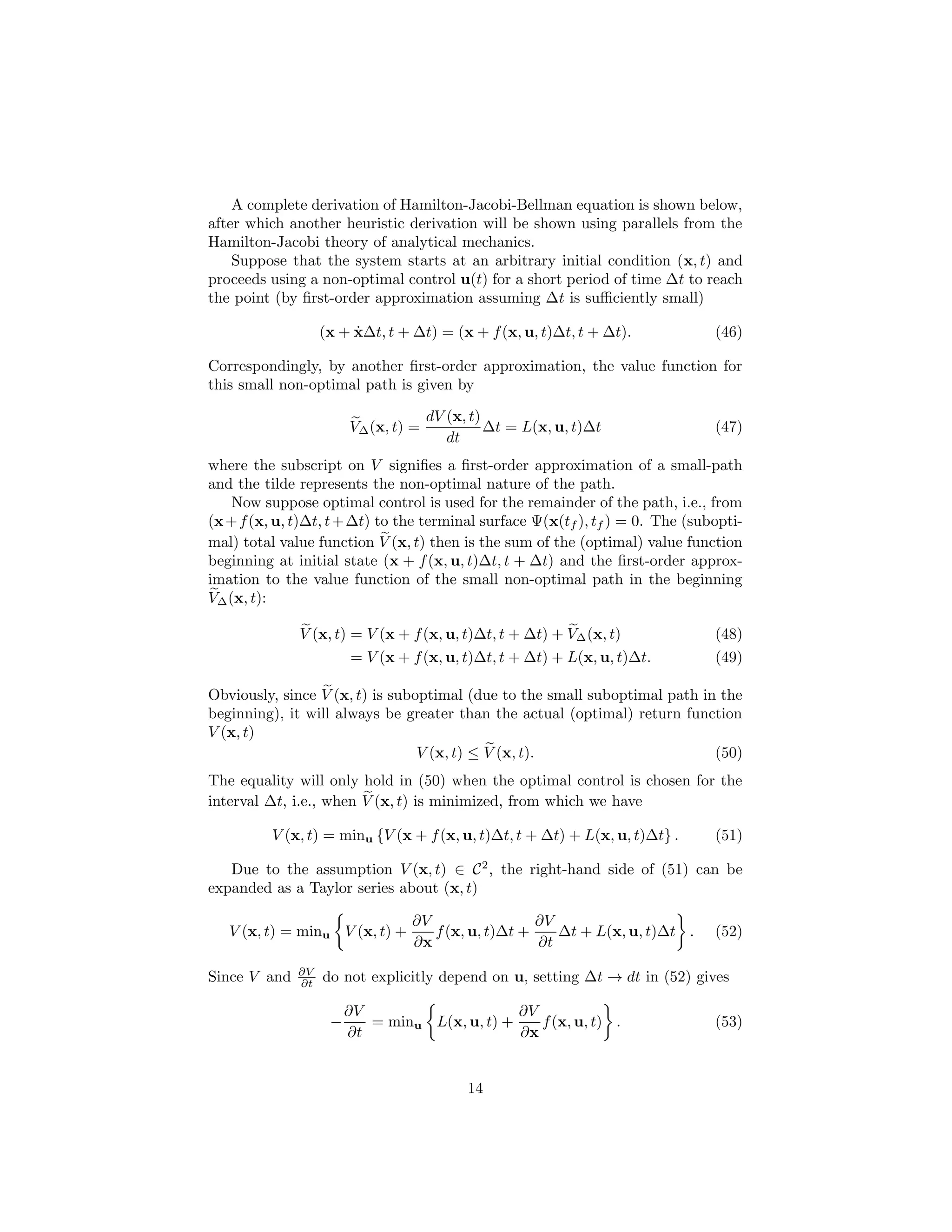
    In the special case where the Hamiltonian is not dependent on time (conser-
vative systems), we have
                                     ∂S
                                H q,     , t = 0.                          (40)
                                     ∂q
The results of this section will be exploited later, at the end of the next section,
to find an elegant solution to the optimal control problem. First, however, a
basic derivation of this result for the optimal control problem, not drawing on
the analogy from analytical mechanics, is presented in the next section.


7    Optimal Feedback Control via the Hamilton-
     Jacobi-Bellman formulation
The problem of finding an optimal control u∗ (t) to proceed from a specified
initial state x(t0 ) to a terminal surface described by Ψ(x(tf ), tf ) = 0 has been
considered so far. A result was derived (Euler-Lagrange optimal control) to
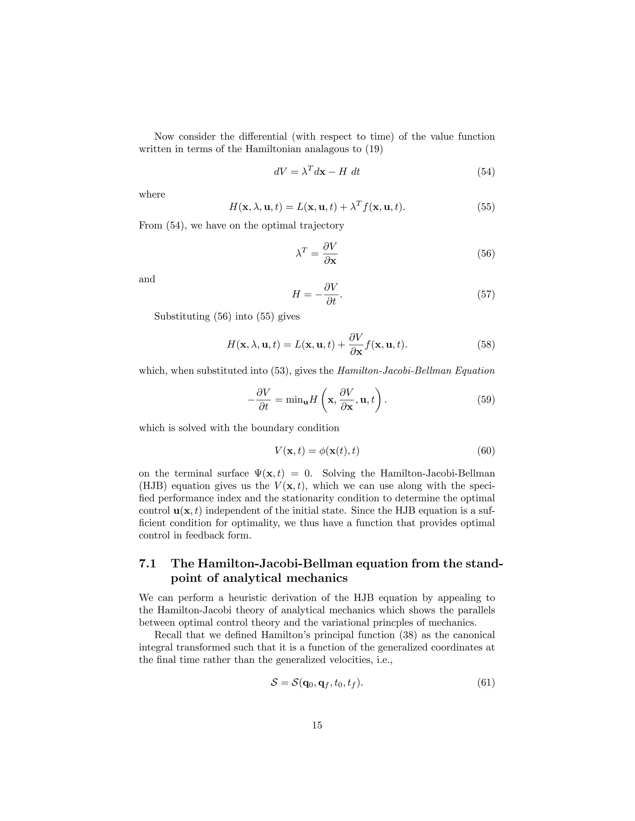
determine the optimal control that minimizes the performance index
                                             tf
                    J = φ(x(tf ), tf ) +          L(x(t), u(t), t) dt          (41)
                                            t0


                                           12
and satisfies the final-state constraint (or terminal surface)

                                  Ψ(x(tf ), tf ) = 0                                  (42)

where the system dynamics are given by

                ˙
                x(t) = f (x(t), u(t), t);        x(t0 );          t0 ≤ t ≤ tf         (43)

Implicit in this discussion was that if the initial state x(t0 ) was changed and
selected on the path from the initial point to the terminal surface determined
by optimal control, then the resulting (new) optimal path would lie on the same
path as previously except for beginning at the new initial state. In a significant
omission, the possibility of other completely arbitrary initial states that do not
lie on the original optimal path was not considered. Indeed, according to the
previous discussion, if another initial state that does not lie on the original
path is specified, then the optimal problem must be considered anew and the
optimal control Euler-Lagrange equations must be solved anew. Since in reality
an infinite number of initial conditions exist, if an efficient method for solving
the optimal control Euler-Lagrange equations is not available (and often it is
not), the previous optimal control results do not prove very useful. The optimal
control Euler-Lagrange equations provide an open-loop or feedforward control
that do not require the system state information at any time other than the
initial and final time (hence the name: two-point boundary-value problem).
    It is preferred to have a family of paths that reach the terminal surface
Ψ(x(tf ), tf ) = 0 from a family of arbitrary initial states x(t0 ). Each of these
paths is the optimal path, with respect to the performance index, from the initial
state to the terminal surface. Thus, the family of paths is a family of optimal
paths or extremals which, in a continuous setting, should be representable by an
initial state dependent function. This allows the formation of feedback control
law rather than the feedforward type control provided by the Euler-Lagrange
formulation.
    The most obvious strategy for forming this initial state dependent function
is to use the only two properties possessed by all the optimal paths: each path
is optimal with respect to the performance index and each path ends at the
terminal surface Ψ(x(tf ), tf ) = 0. Consider then, the cost of an optimal path
starting from an arbitrary initial state (initial state x at time t) and ending
at the terminal surface. This function is called the value function or optimal
return function and is given by
                                                        tf
          V (x, t) = minu(t) φ(x(tf ), tf ) +                L(x(τ ), u(τ ), τ ) dτ   (44)
                                                    t

with boundary condition
                                V (x, t) = φ(x(t), t).                                (45)
on the terminal surface Ψ(x(t), t) = 0. For considerations here, we assume that
value function V (x, t) ∈ C 2 over the interval of interest. The qualifier minu(t)
implies that the evaluation of the value function is along the optimal trajectory.


                                            13
A complete derivation of Hamilton-Jacobi-Bellman equation is shown below,
after which another heuristic derivation will be shown using parallels from the
Hamilton-Jacobi theory of analytical mechanics.
    Suppose that the system starts at an arbitrary initial condition (x, t) and
proceeds using a non-optimal control u(t) for a short period of time ∆t to reach
the point (by first-order approximation assuming ∆t is sufficiently small)

                        ˙
                   (x + x∆t, t + ∆t) = (x + f (x, u, t)∆t, t + ∆t).             (46)

Correspondingly, by another first-order approximation, the value function for
this small non-optimal path is given by

                                      dV (x, t)
                        V∆ (x, t) =             ∆t = L(x, u, t)∆t               (47)
                                         dt
where the subscript on V signifies a first-order approximation of a small-path
and the tilde represents the non-optimal nature of the path.
    Now suppose optimal control is used for the remainder of the path, i.e., from
(x + f (x, u, t)∆t, t + ∆t) to the terminal surface Ψ(x(tf ), tf ) = 0. The (subopti-
mal) total value function V (x, t) then is the sum of the (optimal) value function
beginning at initial state (x + f (x, u, t)∆t, t + ∆t) and the first-order approx-
imation to the value function of the small non-optimal path in the beginning
V∆ (x, t):

              V (x, t) = V (x + f (x, u, t)∆t, t + ∆t) + V∆ (x, t)              (48)
                        = V (x + f (x, u, t)∆t, t + ∆t) + L(x, u, t)∆t.         (49)

Obviously, since V (x, t) is suboptimal (due to the small suboptimal path in the
beginning), it will always be greater than the actual (optimal) return function
V (x, t)
                                 V (x, t) ≤ V (x, t).                       (50)
The equality will only hold in (50) when the optimal control is chosen for the
interval ∆t, i.e., when V (x, t) is minimized, from which we have

          V (x, t) = minu {V (x + f (x, u, t)∆t, t + ∆t) + L(x, u, t)∆t} .      (51)

   Due to the assumption V (x, t) ∈ C 2 , the right-hand side of (51) can be
expanded as a Taylor series about (x, t)

                                 ∂V                 ∂V
   V (x, t) = minu V (x, t) +       f (x, u, t)∆t +    ∆t + L(x, u, t)∆t .      (52)
                                 ∂x                 ∂t
              ∂V
Since V and   ∂t   do not explicitly depend on u, setting ∆t → dt in (52) gives

                        ∂V                     ∂V
                    −      = minu L(x, u, t) +    f (x, u, t) .                 (53)
                        ∂t                     ∂x


                                            14
Now consider the differential (with respect to time) of the value function
written in terms of the Hamiltonian analagous to (19)

                               dV = λT dx − H dt                             (54)

where
                    H(x, λ, u, t) = L(x, u, t) + λT f (x, u, t).             (55)
From (54), we have on the optimal trajectory

                                              ∂V
                                    λT =                                     (56)
                                              ∂x
and
                                              ∂V
                                   H=−           .                           (57)
                                              ∂t
   Substituting (56) into (55) gives

                                                     ∂V
                    H(x, λ, u, t) = L(x, u, t) +        f (x, u, t).         (58)
                                                     ∂x
which, when substituted into (53), gives the Hamilton-Jacobi-Bellman Equation

                            ∂V             ∂V
                        −      = minu H x,    , u, t .                       (59)
                            ∂t             ∂x

which is solved with the boundary condition

                               V (x, t) = φ(x(t), t)                         (60)

on the terminal surface Ψ(x, t) = 0. Solving the Hamilton-Jacobi-Bellman
(HJB) equation gives us the V (x, t), which we can use along with the speci-
fied performance index and the stationarity condition to determine the optimal
control u(x, t) independent of the initial state. Since the HJB equation is a suf-
ficient condition for optimality, we thus have a function that provides optimal
control in feedback form.

7.1     The Hamilton-Jacobi-Bellman equation from the stand-
        point of analytical mechanics
We can perform a heuristic derivation of the HJB equation by appealing to
the Hamilton-Jacobi theory of analytical mechanics which shows the parallels
between optimal control theory and the variational princples of mechanics.
    Recall that we defined Hamilton’s principal function (38) as the canonical
integral transformed such that it is a function of the generalized coordinates at
the final time rather than the generalized velocities, i.e.,

                              S = S(q0 , qf , t0 , tf ).                     (61)


                                         15
˙
    Substitute x = f (x, u, t) into the constrained performance index (19) and
let the initial states and control be arbitrarily assigned
                                  tf
           J = φ(xf , tf ) +              H(x(t), u(t), λ(t), t) − λT (t)x(t) dt.
                                                                         ˙            (62)
                                 t0
              = J (x, xf , u, uf , t0 , tf )                                          (63)

where the subscript f indicates evaluation at the final time.
    Now that since J = J (x0 , xf , u0 , uf , t0 , tf ) is not a function of the velocities
˙
x and because φ(xf , tf ) is simply a function evaluated at a single point, i.e. a
constant, defining x and u as an extended system of generalized coordinates,
allows us to set
                             S = J (x0 , x, u0 , u, t0 , tf )                         (64)
    Then the new S function is stationary with respect to the first variation if
it satisfies the Hamilton-Jacobi equation (39). Rearranging (39) and changing
the arguments we have
                                 ∂S         ∂S
                                    = −H x,    , u, t                                 (65)
                                 ∂t         ∂x

which is simply another statement of the HJB equation (59) since by the Hamilton-
Jacobi theory S satisfying the previous partial differential equation immediately
implies that the first variation of the canonical integral (in this case, the per-
formance index) vanishes.

7.2     A Special Case
A special case is discussed here that utilizes the previous results to show an
example of deriving a feedback optimal control u∗ based on the HJB equation.
Specifically, consider a nonlinear system of the form

                                       ˙
                                       x = f (x) + g(x)u                              (66)

where x ∈ Rn (as before), f : Rn → Rn , g : Rn → Rn×m , f (0) = 0 and u is a
control to be determined.
   Let the value function (from the corresponding performance index) be given
by
                                               ∞
                         V (x, u) =                 xT Qx + uT Ru dt                  (67)
                                           t
                                               ∞
                                      =            L(x, u) dt                         (68)
                                           t

where Q ∈ Rn×n and R ∈ Rm×m are symmetric weighting matrices whose
choice is left as a design consideration. The expression in (67) evaluates the
total cost up to tf = ∞. It represents the weighted (by Q and R) squared
sum of the total control effort and state “effort” expended, which is commonly


                                                    16
a quantity that needs to be minimized. There are no final state constraints
specified and therefore, the problem is simply one of regulation, i.e., the system
                                    ˙
must be driven to its equilibrium x = 0. Furthermore, there is no final-state
weighting function. Also, notice that the value function (67) is not dependent
on time because the original system is not dependent on time. This property
will play an important role in the following discussion.
    Similar to the development in (16) through (19), an augmentation of (67)
with the system dynamics multiplied by the costates yield
                                      ∞
                     V (x, u) =           H(x, u, λ) − λT x dt
                                                          ˙                 (69)
                                  t

where
                   H = xT Qx + uT Ru + λT [f (x) + g(x)u] .                 (70)
Rewriting the stationarity condition (29) in terms of the new system equations
gives
                      ∂                              ∂H
                         λT (f (x) + g(x)u) + L =        =0                 (71)
                     ∂u                              ∂u
and hence from (70)
                          ∂H
                                = 2uT R + λT g(x) = 0                       (72)
                           ∂u
where it must be noted that the costate λ is not arbitrary and satisfying (72)
implies that λ is a costate of the optimal control u∗ . We denote this special
costate λ∗ . For purposes of clarity, the expression (72) is transposed and then
rewritten to reflect this
                          ∂H
                              = 2Ru∗ + g T (x)λ∗ = 0.                       (73)
                          ∂u∗
Rearranging (73) gives an expression for the optimal control
                                   1
                             u∗ = − R−1 g T (x)λ∗                           (74)
                                   2
where everything on the right-hand side is known except the “optimal costate”
λ∗ . This is precisely where the HJB equation enters the picture. Since by (56),
we have on the optimal trajectory
                                                 T
                                            ∂V
                                  λ∗ =                                      (75)
                                            ∂x

the expression for the optimal control (74) can be written as
                                                          T
                                1                    ∂V
                          u∗ = − R−1 g T (x)                                (76)
                                2                    ∂x

and hence finding the solution to the HJB equation (which gives V ) allows the
explicit analytic expression of the optimal control u∗ .


                                           17
Notice that since the system under consideration is conservative, i.e., f =
f (x) and g = g(x), the Hamiltonian (70) is not dependent on time

                                 H = H(x, u, λ)                              (77)

and furthermore, the value function (69) is also not dependent on time

                                  V = V (x, u).                              (78)

Therefore, we have
                                  ∂V
                                      =0                                     (79)
                                  ∂t
which implies that the HJB equation (60) reduces to

                                        ∂V
                           minu H x,       , u, t   =0                       (80)
                                        ∂x

over the optimal trajectory. From the expression of the Hamiltonian H (70)

               H = minu xT Qx + uT Ru + λT [f (x) + g(x)u]                   (81)
                                     ∂V
                 = xT Qx + u∗T Ru∗ +    [f (x) + g(x)u∗ ] = 0                (82)
                                     ∂x
which was obtained by using the relationship (75).
   Substituting the optimal control (63) into the modified HJB (75) yields the
partial differential equation

        1                                   ∂V        1
xT Qx+ (R−1 g T (x)λ∗ )T R(R−1 g T (x)λ∗ )+    f (x) − g(x)(R−1 g T (x)λ∗ ) = 0
        4                                   ∂x        2
                                                                          (83)
or by simplifying and using (75)

                ∂V                 1 ∂V                 ∂V
                   f (x) + xT Qx −      g(x)R−1 g T (x)    = 0.              (84)
                ∂x                 4 ∂x                 ∂x
The only unknown in (84) is ∂V or the partial derivative (with respect to the
                               ∂x
states) of the optimal return function/value function. Therefore solving (84) is
sufficient to determine the optimal control (74).
    Unfortunately, solving the partial differential equation (84) is extremely dif-
ficult and frequently impossible. Thus, even though a feedback optimal control
based on the HJB equation, as in (74) is very attractive especially over the
feedforward Euler-Lagrange optimal control solution, the added complexity in
solving a partial differential equation such as (84) strictly limits its direct ap-
plication [8].
    Although several techniques have been proposed to provide a solution to
the HJB equation under special conditions, the problem is still, even after five
decades, an active area of research. One such a technique is presented in the
next section in significant detail.


                                       18
8    Generalized Hamilton-Jacobi Bellman Equa-
     tion
Traditionally, the challenge of solving a partial differential equation like (84)
was tackled using what is known as the “method of characteristics” [8]. The
basic idea behind this method is to reduce the partial differential equation into
a family of ordinary differential equations which are then integrated over differ-
ent initial conditions to the terminal surface to obtain solutions to the partial
differential equation. Such a scheme is very useful in studying the qualitative
behavior of partial differential equations and has extensive applications in (com-
putational) fluid mechanics where it is used to study phenomena such as turbu-
lence and shockwaves via the Navier-Stokes equations. However, its application
in optimal control is not particularly beneficial. Firstly, the computation and
storage of solutions of (infinitely) large sets of ordinary differential equations
and initial conditions is prohibitive. In fact, this eliminates one of main reasons
of using the HJB solution to the optimal control problem; to avoid computa-
tion of arbitarily large numbers of solutions to the two-point boundary value
problem. Secondly, the solutions via the characteristic equations are not always
well-defined. Specifically, under certain conditions, multivalued solutions might
appear. Thirdly, in many cases, the method of characteristics does not cover the
entire domain of the partial differential equation and the solution only exists in
a weak sense. Despite these apparently critically shortcomings, during the early
years of optimal control, the method of characteristics was often considered the
only route to achieve a practical solution to the optimal control problem via the
HJB equation.
    During the 1970’s, other more efficient techniques hinging on system linearity
were developed to solve the HJB equation to obtain a feedback optimal control.
If the system nonlinearities are small, peturbation methods can be used to
achieve second-order approximations to the optimal control as was shown in
[12, 20, 10, 11]. An explicit assumption in these is that the optimal control has
a sufficiently accurate second-order Taylor series expansion about the origin.
This type of assumption severly limits the class of systems to which the method
is applicable. The stability region of the resulting control is also almost always
impossible to determine. Perturbation methods, therefore, did not gain much
momentum as viable schemes for numerical feedback optimal control.
    As feedback linearization (or dynamic inversion) and geometric control gained
popularity during the late 1980’s and 1990’s, several new attempts were made at
attacking the numerical feedback optimal control problem. All of these involved
canceling system nonlinearities via feedback (dynamic inversion) and then ap-
plying optimal control theory to the subsequent linearized system [14, 9, 27].
This method has several drawbacks: significant control effort is expended in
forcing the nonlinear system to behave linearly, useful nonlinearities that may
help in control are eliminated, the dynamic inversion of the control matrix is not
always a global transformation, the dynamic inversion itself is computationally
expensive and finally, the dynamic inversion is fragile to modeling uncertainties


                                        19
and disturbances.
    Another approach to utilizing the HJB equation for optimal feedback control
takles the problem not by determining an optimal control u∗ but rather by suc-
cessively optimizing an existing stabilizing suboptimal control u(0) . The method
utilizes an alternative formulation of the Hamilton-Jacobi equation known as the
generalized Hamilton-Jacobi-Bellman equation and was first proposed by Saridis
and Lee in [24]. The design methodology was further refined in [2, 17, 3] by
introducing the use of Galerkin’s spectral method to approximate partial dif-
ferential equations. The following is a detailed mathematical treatment of this
methodology using previously derived results in this report.
    Consider a suboptimal stabilizing feedback control u(x) for the (conserva-
tive) nonlinear system (66). Analagous to (67), let the suboptimal value function
for this particular control be given by
                                  ∞
                    V (x) =           xT Qx + uT (x)Ru(x) dt.               (85)
                              t

We say that a feedback control u ∈ Ωu is admissible if u is continous and renders
(66) asymptotically stable.
    Assuming an admissible but suboptimal u is given, can the HJB equation
be exploited to optimize this control successively over time? This question was
first addressed by Saridis and Lee in [24] where they introduced the concept
of the generalized Hamilton-Jacobi-Bellman equation. The equation was thus
named because it applied to all types of u and not just an optimal control. It
is introduced here based on previous results in a nonrigorous fashion.
    Differentiating the suboptimal value function (85) along the trajectories of
the system yields the differential form of the (suboptimal) value function

                  ∂V T
     GHJB :            [f (x) + g(x)u(x)] + xT Qx + uT (x)Ru(x) = 0.        (86)
                   ∂x
This differential form of the (suboptimal) value function is known as the gener-
alized Hamilton-Jacobi-Bellman (GHJB) equation. The solution of the GHJB
equation V is a Lyapunov function for (66) under the suboptimal control u [1].
It represents the value function under a suboptimal control.
    The development below closely follows Saridis and Lee [24]. Key theorems
are reproduced (in a standardized form) and presented without the proofs. The
first lemma relates the suboptimal value function V (x) to the true value function
V (x) under optimal control.
Lemma 1 Assume the optimal control u∗ and the optimal value function V (x)
exist. Then these satisfy the GHJB equation (86) and

                                  0 < V (x) ≤ V (x).                        (87)


The next theorem presents an approach to ensure a successively (at each step
or iteration) smaller suboptimal value function.


                                          20
Theorem 1 If a sequence of pairs {u(i) , V (i) } satisfying the GHJB equation
(86) is generated by selecting the control u(i) to minimize the GHJB equation
associated with the previous value function V (i−1) , e.g.,

                                    1        ∂ V (i−1)
                            u(i) = − g T (x)                                 (88)
                                    2           ∂x
then the corresponding value function satisfies the inequality

                                  V (i) ≤ V (i−1) .                          (89)


Note the similarity between (88) and general expression for the optimal control
(76). The corollary that follows is intuitively immediate from Lemma 1 and
Theorem 1. It deals with the convergence of a sequence of suboptimal value
functions to the optimal value function given a control such as (88)

Corollary 1 By selecting pairs {u(i) , V (i) } with

                                    1        ∂ V (i−1)
                            u(i) = − g T (x)                                 (90)
                                    2           ∂x

the resulting sequence {V (i) } converges monotonically to the optimal value func-
tion V (x) associated with the optimal control, i.e.,

                         V (0) ≥ V (1) ≥ V (2) ≥ . . . ≥ V.                  (91)


The final two theorems deal with construction of upper and lower bounds for
the true value function V (x). This is accomplished by obtaining functions that
only marginally do not satisfy the GHJB equation on both sides (< 0 and > 0).
Theorem 2 Suppose for a given us (x) and some

                                 s(x), |s(x)| < ∞                            (92)

there exists a continously differentiable positive definite function Vs = V (x, us )
satisfying the properties

    ∂ VsT
          [f (x) + g(x)u(x)] + xT Qx + uT (x)Ru(x) = ∆Vs ≤ s(x) < 0          (93)
     ∂x

Then Vs (x) is an upper bound of the optimal value function V (x)

                                  Vs (x) > V (x).                            (94)


                                         21
And similarly for the lower bound, we have the last theorem.
Theorem 3 Suppose for a given us (x) and some

                                s(x), |s(x)| < ∞                             (95)

there exists a continously differentiable positive definite function Vs = V (x, us )
satisfying the properties

    ∂ VsT
          [f (x) + g(x)u(x)] + xT Qx + uT (x)Ru(x) = ∆Vs ≥ s(x) > 0          (96)
     ∂x

Then Vs (x) is a lower bound of the optimal value function V (x)

                                 Vs (x) < V (x).                             (97)


   An exact design procedure for optimizing an initial admissible control u(0) ∈
Ωu can now be formed from the previous results.
  1. Select an initial admissible control u(0) ∈ Ωu for the system (66).

  2. Solve the GHJB partial differential equation to find V (0)

          ∂ V (0)T
                   f (x) + g(x)u(0) (x) + xT Qx + u(0)T (x)Ru(0) (x) = 0. (98)
             ∂x

     Then by Lemma 1, V (0) ≥ V .
  3. Obtain an improved controller u(1) using Corollary 1

                                       1        ∂ V (0)
                               u(1) = − g T (x)         .                    (99)
                                       2          ∂x

  4. Solve the GHJB partial differential equation to find V (1)

          ∂ V (1)T
                   f (x) + g(x)u(1) (x) +xT Qx+u(1)T (x)Ru(1) (x) = 0. (100)
             ∂x

     Then by Lemma 1, V (0) > V (1) ≥ V .
  5. Determine a lower bound Vs to the optimal value function using Theorem
     3.
  6. Use V (1) − Vs as a measure to evaluate how close an approximation u(1)
     is to the optimal control u∗ . If acceptable, stop at this iteration.
  7. Otherwise, if the approximation is not acceptable, repeat from step 2
     onwards with a new iteration.


                                       22
The benefit of using the GHJB equation and the control design procedure
outlined is that we do not need to solve the HJB partial differential equation
equation (84) directly. Rather, a much more amenable partial differential equa-
tion needs to be solved in the form of the GHJB (86). Furthermore, the GHJB
allows for an iteratively improving solution that addresses several implementa-
tion challenges. Rather than have to solve the entire optimal control problem
at once, the solution is divided into successively improving iterations, each of
which is useful in the control action since each is always better than the initial
designed stabilizing controller.
    A method to solve the GHJB equation is considered below.


9     Succesive Galerkin Approximation to the GHJB
      Equation
The solution to the GHJB equation (86) needs to be numerically determined in
order to utilize the design procedure outlined above. This problem was tackled
by Beard in his doctoral work [2] and in the subsequent journal publication [3].
An algorithm called Succesive Galerkin Approximation (SGA) was developed
based on the spectral method of Galerkin. A numerically efficient version of the
algorithm was also developed in [17]. Most famously, a discussion of the method
by Beard, Saridis and Wen appeared in the IEEE Control Engineering Magazine
[1]. This section provides an outline of the method with its key points.
    Let the system (66) be Lipschitz continous on a set Ω ⊂ Rn containing the
origin. Furthermore, let there exist a continous control on Ω that asymptotically
stabilizes the system, i.e., the system is controllable over Ω. Now assume the
existence of a set of basis functions {φj }∞ , where φj : Ω → Rn are continous,
                                           1
φ(0) = 0 and span{φj }∞ ⊆ L2 (Ω). Then the solution V of the GHJB equation
                        1
(86) can be written as
                                         ∞
                               V (x) =         cj φj (x)
                                               ˆ                            (101)
                                         j=1

where the cj are constants to be determined. It is not practical to have an
           ˆ
infinite summation as an approximation, and thus a large enough number N is
chosen to truncate the solution. This truncated solution is referred to as VN
and from (101), it is given by

                               VN (x) = cT ΦN (x)
                                        ˆN                                  (102)

where
                              cT = c 1
                              ˆN   ˆ          ...   cN
                                                    ˆ                       (103)
and
                                                              T
                        ΦN (x) = φ1 (x) . . .        φN (x)                 (104)


                                         23
ˆ
   The vector of N constants cN is determined by ensuring orthogonality be-
tween the GHJB expressed in terms of VN (x) and ΦN (x), i.e.,

                                 GHJB VN (x) , ΦN (x)                  =0                     (105)
                                                                  Ω

where ., . Ω denotes the function inner product (integral) over the set Ω. Note
that in (105), the expression (101) is used. It follows that (105) is system of
N linear equations with N unknows. The system can be easily inverted to
           ˆ
determine cN as is shown in the following discussion.
   The GHJB equation from (105) (in terms of the truncated approximation of
the suboptimal value function) is written as

        T
     ∂ VN
          [f (x) + g(x)u(x)] + xT Qx + uT (x)Ru(x)
      ∂x
                        ∂ΦN (x)
                   = cT
                     ˆN         [f (x) + g(x)u(x)] + xT Qx + uT (x)Ru(x)                      (106)
                          ∂x
where ∂ΦN /∂x ∈ RN ×n is a matrix quantity. For convenience denote this as
                                                                                     T
                  ∂ΦN (x)                        ∂φ1 (x)                ∂φN (x)
                          =          ΦN (x) =                    ...                     .    (107)
                    ∂x                             ∂x                     ∂x

Then from (106), it follows that the GHJB equation is

               cT ΦN (x) [f (x) + g(x)u(x)] + xT Qx + uT (x)Ru(x) .
               ˆN                                                                             (108)

Transposing (108)
                                     T
               [f (x) + g(x)u(x)]        ΦT (x)ˆN + xT Qx + uT (x)Ru(x) .
                                          N    c                                              (109)

and then substituting into (109) yields
                       T
 [f (x) + g(x)u(x)]        ΦT (x), ΦN
                            N                   cN + xT Qx, ΦN
                                                ˆ                        Ω
                                                                             + uT (x)Ru(x), ΦN   Ω
                                                                                                     = 0.
                                            Ω
                                                                                              (110)
or

                              T
            [f (x) + g(x)u(x)]        ΦT (x)ΦN
                                       N              ˆ
                                                      cN +       xT QxΦN +           uT (x)Ru(x), ΦN
       Ω                                                     Ω                   Ω
                                 T
=           [f (x) + g(x)u(x)]        ΦT (x)ΦN
                                       N              ˆ
                                                      cN +             xT Qx + uT (x)Ru(x) ΦN
        Ω                                                        Ω
                                                                             = aˆN + b = 0.
                                                                                c             (111)

where a ∈ R, cN ∈ RN and b ∈ RN . Thus cj maybe found element by element
             ˆ                         ˆ
using
                                      bj
                               cj = −
                               ˆ                                    (112)
                                      a

                                                 24
where bj is the j-th element of b. Once these are determined, (102) is used
to form the truncated approximation of the suboptimal value function. The
convergence and validity proofs for this type of approximation is dealt with in
[2].
     The basis functions have not been discussed so far. Polynomials, in most
cases, are sufficient. Moreover, if these are orthogonal, better results are ex-
pected. Increasing the number of these basis functions, i.e., increasing N , has
an exponential effect on the computation required [17]. It is therefore, impor-
tant to choose the basis vectors carefully. Lawton and Beard showed in [17]
that choosing the basis functions such that they are separable and assuming the
domain Ω to be rectangular allows for the formulation of significantly compu-
tationally cheaper versions of the SGA algorithm. Polynomials are separable
functions and therefore play an important role in that work.
     Despite the attractiveness of the methods presented, they still pose chal-
lenges when it comes to addressing one of the prime reasons for utilizing the
HJB equation for optimal control; to allow for a closed-form solution to the op-
timal feedback problem that can be used efficiently in realistic scenarios. In this
respect, the GHJB/SGA algorithm is not unique among the other methodolo-
gies in numerical optimal feedback control. As the system order increases and
computational resources become more restrictive, most methodologies become
infeasible. Thus, using such algorithms in embedded systems or to efficiently
control complex systems (like aircraft) is often impossible.


10     Conclusion
A broad discussion of optimal control was presented. A history and the basic
problem of optimal control were shown. This was followed by a derivation of
standard results in optimal control theory along with discussions of the connec-
tions between classical mechanics and optimal control theory. The report ended
with a discussion of more recent results in optimal control theory, namely, results
to make optimal control theory more practically viable.
    Even half a century after the initial results published independently by Bell-
man and Pontryagin, optimal control remains a vibrant area of research with
much sought after results. Rather than recede to the background in light of
the latest developments, optimal control is becoming more and more relevant.
This is not least because of the huge strides achieved in computational power.
Mathematical developments and the race towards achieving computationally vi-
able schemes for simulation also indirectly benefit optimal control theory. With
its wide applications and promise for future research, optimal control remains
a high value research area. Since the theoretical foundation of optimal control
theory has already been laid, this high value research is geared towards achieving
numerical schemes to make optimal control more practical.


                                        25
References
 [1] R. Beard, G. Saridis, and J. Wen, “Improving the performance of stabilizing
     controls for nonlinear systems,” Control Systems Magazine, IEEE, vol. 16,
     no. 5, pp. 27–35, 1996.
 [2] R. Beard, “Improving the closed-loop performance of nonlinear systems,”
     Ph.D. dissertation, Rensselaer Polytechnic Institute, 1995.

 [3] R. Beard, G. Saridis, and J. Wen, “Galerkin approximations of the gener-
     alized Hamilton-Jacobi-Bellman equation* 1,” Automatica, vol. 33, no. 12,
     pp. 2159–2177, 1997.
 [4] R. Bellman, “On the theory of dynamic programming,” Proceedings of the
     National Academy of Sciences of the United States of America, vol. 38,
     no. 8, p. 716, 1952.
 [5] ——, The theory of dynamic programming. Defense Technical Information
     Center, 1954.
 [6] ——, “An introduction to the theory of dynamic programming.” 1953.

 [7] ——, Eye of the Hurricane: an Autobiography.       World Scientific, 1984.
 [8] A. Bryson and Y. Ho, Applied optimal control.        American Institute of
     Aeronautics and Astronautics, 1979.
 [9] L. Gao, L. Chen, Y. Fan, and H. Ma, “A nonlinear control design for power
     systems,” Automatica, vol. 28, no. 5, pp. 975–979, 1992.
[10] W. Garrard, “Suboptimal feedback control for nonlinear systems,” Auto-
     matica, vol. 8, no. 2, pp. 219–221, 1972.
[11] W. Garrard and J. Jordan, “Design of nonlinear automatic flight control
     systems,” Automatica, vol. 13, no. 5, pp. 497–505, 1977.

[12] W. Garrard, N. McClamroch, and L. Clark, “An approach to sub-optimal
     feedback control of non-linear systems,” International Journal of Control,
     vol. 5, no. 5, pp. 425–435, 1967.
[13] H. Goldstein, C. Poole, J. Safko, and S. Addison, “Classical mechanics,”
     American Journal of Physics, vol. 70, p. 782, 2002.
[14] A. Isidori, Nonlinear control systems.   Springer Verlag, 1995.
[15] A. Klumpp, “Apollo lunar descent guidance,” Automatica, vol. 10, no. 2,
     pp. 133–146, 1974.

[16] C. Lanczos, The variational principles of mechanics. Dover Publications,
     1970.


                                       26
[17] J. Lawton and R. Beard, “Numerically efficient approximations to the
     Hamilton-Jacobi-Bellman equation,” in American Control Conference,
     1998. Proceedings of the 1998, vol. 1. IEEE, 1998, pp. 195–199.
[18] F. Lewis, Applied optimal control and estimation.     Prentice Hall PTR,
     1992.

[19] F. Lewis and V. Syrmos, Optimal control.    Wiley-Interscience, 1995.
[20] Y. Nishikawa, N. Sannomiya, and H. Itakura, “A method for suboptimal
     design of nonlinear feedback systems,” Automatica, vol. 7, no. 6, pp. 703–
     712, 1971.

[21] J. Papastavridis and J. Papastavridis, Analytical Mechanics. Oxford Uni-
     versity Press, 2002.
[22] L. Pontryagin, “Optimal regulation processes,” Uspekhi Matematicheskikh
     Nauk, vol. 14, no. 1, pp. 3–20, 1959.

[23] L. Pontryagin, V. Boltyanskii, R. Gamkrelidze, and E. Mishchenko, The
     mathematical theory of optimal control processes. Interscience, New York,
     1962.
[24] G. Saridis and C. Lee, “An approximation theory of optimal control for
     trainable manipulators,” Systems, Man and Cybernetics, IEEE Transac-
     tions on, vol. 9, no. 3, pp. 152–159, 1979.
[25] S. Sethi and G. Thompson, Optimal control theory: applications to man-
     agement science and economics. Springer Verlag, 2005.
[26] H. Sussmann and J. Willems, “300 years of optimal control: from the
     brachystochrone to the maximum principle,” Control Systems Magazine,
     IEEE, vol. 17, no. 3, pp. 32–44, 1997.
[27] Y. Wang, D. Hill, R. Middleton, and L. Gao, “Transient stabilization of
     power systems with an adaptive control law* 1,” Automatica, vol. 30, no. 9,
     pp. 1409–1413, 1994.

[28] J. Willems, “1696: the birth of optimal control,” in Decision and Control,
     1996., Proceedings of the 35th IEEE, vol. 2. IEEE, 1996, pp. 1586–1587.


                                      27

More Related Content

Similar to Optimal Control: Perspectives from the Variational Principles of Mechanics

Geometric Control System and Fault-Diagnosis
Geometric Control System and Fault-Diagnosis Geometric Control System and Fault-Diagnosis
Geometric Control System and Fault-Diagnosis
M Reza Rahmati
 
Hamiltonian formulation project Sk Serajuddin.pdf
Hamiltonian formulation project Sk Serajuddin.pdfHamiltonian formulation project Sk Serajuddin.pdf
Hamiltonian formulation project Sk Serajuddin.pdf
miteshmohanty03
 
ObservabilityForModernApplications-Oslo.pdf
ObservabilityForModernApplications-Oslo.pdfObservabilityForModernApplications-Oslo.pdf
ObservabilityForModernApplications-Oslo.pdf
Amazon Web Services
 
12 102-1-pb
12 102-1-pb12 102-1-pb
12 102-1-pb
John Varn II
 
Talk_MR_ver_b_2
Talk_MR_ver_b_2Talk_MR_ver_b_2
Talk_MR_ver_b_2
Michele Romeo
 
Observability for modern applications
Observability for modern applications  Observability for modern applications
Observability for modern applications
MoovingON
 
Approaches To The Solution Of Intertemporal Consumer Demand Models
Approaches To The Solution Of Intertemporal Consumer Demand ModelsApproaches To The Solution Of Intertemporal Consumer Demand Models
Approaches To The Solution Of Intertemporal Consumer Demand Models
Amy Isleb
 
computational pnnnnnnnnnnnnnnnnnnnnnnnnnnnnnpt.pptx
computational pnnnnnnnnnnnnnnnnnnnnnnnnnnnnnpt.pptxcomputational pnnnnnnnnnnnnnnnnnnnnnnnnnnnnnpt.pptx
computational pnnnnnnnnnnnnnnnnnnnnnnnnnnnnnpt.pptx
KeyredinWabela
 
kalman_maybeck_ch1.pdf
kalman_maybeck_ch1.pdfkalman_maybeck_ch1.pdf
kalman_maybeck_ch1.pdf
LeonardoMMarques
 
ObservabilityForModernApplications_Stockholm.pdf
ObservabilityForModernApplications_Stockholm.pdfObservabilityForModernApplications_Stockholm.pdf
ObservabilityForModernApplications_Stockholm.pdf
Amazon Web Services
 
2014 10 rotman mecnhanism and climate models
2014 10 rotman mecnhanism and climate models 2014 10 rotman mecnhanism and climate models
2014 10 rotman mecnhanism and climate models
Ioan Muntean
 
Advances in-the-theory-of-control-signals-and-systems-with-physical-modeling-...
Advances in-the-theory-of-control-signals-and-systems-with-physical-modeling-...Advances in-the-theory-of-control-signals-and-systems-with-physical-modeling-...
Advances in-the-theory-of-control-signals-and-systems-with-physical-modeling-...
Nick Carter
 
A guide to molecular mechanics and quantum chemical calculations
A guide to molecular mechanics and quantum chemical calculationsA guide to molecular mechanics and quantum chemical calculations
A guide to molecular mechanics and quantum chemical calculations
Sapna Jha
 
Research_paper
Research_paperResearch_paper
Research_paper
Sami D'Almeida
 
Introduction to mathematical modelling
Introduction to mathematical modellingIntroduction to mathematical modelling
Introduction to mathematical modelling
Arup Kumar Paria
 
Application of First Order Linear Equation Market Balance
Application of First Order Linear Equation Market BalanceApplication of First Order Linear Equation Market Balance
Application of First Order Linear Equation Market Balance
ijtsrd
 
scalar field inflation
scalar field inflationscalar field inflation
scalar field inflation
Ali Kokaz
 
Monoton-working version-1995.doc
Monoton-working version-1995.docMonoton-working version-1995.doc
Monoton-working version-1995.doc
butest
 
Monoton-working version-1995.doc
Monoton-working version-1995.docMonoton-working version-1995.doc
Monoton-working version-1995.doc
butest
 
Metaheuristic Optimization: Algorithm Analysis and Open Problems
Metaheuristic Optimization: Algorithm Analysis and Open ProblemsMetaheuristic Optimization: Algorithm Analysis and Open Problems
Metaheuristic Optimization: Algorithm Analysis and Open Problems
Xin-She Yang
 

Similar to Optimal Control: Perspectives from the Variational Principles of Mechanics (20)

Geometric Control System and Fault-Diagnosis
Geometric Control System and Fault-Diagnosis Geometric Control System and Fault-Diagnosis
Geometric Control System and Fault-Diagnosis
 
Hamiltonian formulation project Sk Serajuddin.pdf
Hamiltonian formulation project Sk Serajuddin.pdfHamiltonian formulation project Sk Serajuddin.pdf
Hamiltonian formulation project Sk Serajuddin.pdf
 
ObservabilityForModernApplications-Oslo.pdf
ObservabilityForModernApplications-Oslo.pdfObservabilityForModernApplications-Oslo.pdf
ObservabilityForModernApplications-Oslo.pdf
 
12 102-1-pb
12 102-1-pb12 102-1-pb
12 102-1-pb
 
Talk_MR_ver_b_2
Talk_MR_ver_b_2Talk_MR_ver_b_2
Talk_MR_ver_b_2
 
Observability for modern applications
Observability for modern applications  Observability for modern applications
Observability for modern applications
 
Approaches To The Solution Of Intertemporal Consumer Demand Models
Approaches To The Solution Of Intertemporal Consumer Demand ModelsApproaches To The Solution Of Intertemporal Consumer Demand Models
Approaches To The Solution Of Intertemporal Consumer Demand Models
 
computational pnnnnnnnnnnnnnnnnnnnnnnnnnnnnnpt.pptx
computational pnnnnnnnnnnnnnnnnnnnnnnnnnnnnnpt.pptxcomputational pnnnnnnnnnnnnnnnnnnnnnnnnnnnnnpt.pptx
computational pnnnnnnnnnnnnnnnnnnnnnnnnnnnnnpt.pptx
 
kalman_maybeck_ch1.pdf
kalman_maybeck_ch1.pdfkalman_maybeck_ch1.pdf
kalman_maybeck_ch1.pdf
 
ObservabilityForModernApplications_Stockholm.pdf
ObservabilityForModernApplications_Stockholm.pdfObservabilityForModernApplications_Stockholm.pdf
ObservabilityForModernApplications_Stockholm.pdf
 
2014 10 rotman mecnhanism and climate models
2014 10 rotman mecnhanism and climate models 2014 10 rotman mecnhanism and climate models
2014 10 rotman mecnhanism and climate models
 
Advances in-the-theory-of-control-signals-and-systems-with-physical-modeling-...
Advances in-the-theory-of-control-signals-and-systems-with-physical-modeling-...Advances in-the-theory-of-control-signals-and-systems-with-physical-modeling-...
Advances in-the-theory-of-control-signals-and-systems-with-physical-modeling-...
 
A guide to molecular mechanics and quantum chemical calculations
A guide to molecular mechanics and quantum chemical calculationsA guide to molecular mechanics and quantum chemical calculations
A guide to molecular mechanics and quantum chemical calculations
 
Research_paper
Research_paperResearch_paper
Research_paper
 
Introduction to mathematical modelling
Introduction to mathematical modellingIntroduction to mathematical modelling
Introduction to mathematical modelling
 
Application of First Order Linear Equation Market Balance
Application of First Order Linear Equation Market BalanceApplication of First Order Linear Equation Market Balance
Application of First Order Linear Equation Market Balance
 
scalar field inflation
scalar field inflationscalar field inflation
scalar field inflation
 
Monoton-working version-1995.doc
Monoton-working version-1995.docMonoton-working version-1995.doc
Monoton-working version-1995.doc
 
Monoton-working version-1995.doc
Monoton-working version-1995.docMonoton-working version-1995.doc
Monoton-working version-1995.doc
 
Metaheuristic Optimization: Algorithm Analysis and Open Problems
Metaheuristic Optimization: Algorithm Analysis and Open ProblemsMetaheuristic Optimization: Algorithm Analysis and Open Problems
Metaheuristic Optimization: Algorithm Analysis and Open Problems
 

Recently uploaded

[OReilly Superstream] Occupy the Space: A grassroots guide to engineering (an...
[OReilly Superstream] Occupy the Space: A grassroots guide to engineering (an...[OReilly Superstream] Occupy the Space: A grassroots guide to engineering (an...
[OReilly Superstream] Occupy the Space: A grassroots guide to engineering (an...
Jason Yip
 
Astute Business Solutions | Oracle Cloud Partner |
Astute Business Solutions | Oracle Cloud Partner |Astute Business Solutions | Oracle Cloud Partner |
Astute Business Solutions | Oracle Cloud Partner |
AstuteBusiness
 
Fueling AI with Great Data with Airbyte Webinar
Fueling AI with Great Data with Airbyte WebinarFueling AI with Great Data with Airbyte Webinar
Fueling AI with Great Data with Airbyte Webinar
Zilliz
 
How to Interpret Trends in the Kalyan Rajdhani Mix Chart.pdf
How to Interpret Trends in the Kalyan Rajdhani Mix Chart.pdfHow to Interpret Trends in the Kalyan Rajdhani Mix Chart.pdf
How to Interpret Trends in the Kalyan Rajdhani Mix Chart.pdf
Chart Kalyan
 
“How Axelera AI Uses Digital Compute-in-memory to Deliver Fast and Energy-eff...
“How Axelera AI Uses Digital Compute-in-memory to Deliver Fast and Energy-eff...“How Axelera AI Uses Digital Compute-in-memory to Deliver Fast and Energy-eff...
“How Axelera AI Uses Digital Compute-in-memory to Deliver Fast and Energy-eff...
Edge AI and Vision Alliance
 
Northern Engraving | Nameplate Manufacturing Process - 2024
Northern Engraving | Nameplate Manufacturing Process - 2024Northern Engraving | Nameplate Manufacturing Process - 2024
Northern Engraving | Nameplate Manufacturing Process - 2024
Northern Engraving
 
Digital Banking in the Cloud: How Citizens Bank Unlocked Their Mainframe
Digital Banking in the Cloud: How Citizens Bank Unlocked Their MainframeDigital Banking in the Cloud: How Citizens Bank Unlocked Their Mainframe
Digital Banking in the Cloud: How Citizens Bank Unlocked Their Mainframe
Precisely
 
Dandelion Hashtable: beyond billion requests per second on a commodity server
Dandelion Hashtable: beyond billion requests per second on a commodity serverDandelion Hashtable: beyond billion requests per second on a commodity server
Dandelion Hashtable: beyond billion requests per second on a commodity server
Antonios Katsarakis
 
Columbus Data & Analytics Wednesdays - June 2024
Columbus Data & Analytics Wednesdays - June 2024Columbus Data & Analytics Wednesdays - June 2024
Columbus Data & Analytics Wednesdays - June 2024
Jason Packer
 
Energy Efficient Video Encoding for Cloud and Edge Computing Instances
Energy Efficient Video Encoding for Cloud and Edge Computing InstancesEnergy Efficient Video Encoding for Cloud and Edge Computing Instances
Energy Efficient Video Encoding for Cloud and Edge Computing Instances
Alpen-Adria-Universität
 
Connector Corner: Seamlessly power UiPath Apps, GenAI with prebuilt connectors
Connector Corner: Seamlessly power UiPath Apps, GenAI with prebuilt connectorsConnector Corner: Seamlessly power UiPath Apps, GenAI with prebuilt connectors
Connector Corner: Seamlessly power UiPath Apps, GenAI with prebuilt connectors
DianaGray10
 
Principle of conventional tomography-Bibash Shahi ppt..pptx
Principle of conventional tomography-Bibash Shahi ppt..pptxPrinciple of conventional tomography-Bibash Shahi ppt..pptx
Principle of conventional tomography-Bibash Shahi ppt..pptx
BibashShahi
 
Freshworks Rethinks NoSQL for Rapid Scaling & Cost-Efficiency
Freshworks Rethinks NoSQL for Rapid Scaling & Cost-EfficiencyFreshworks Rethinks NoSQL for Rapid Scaling & Cost-Efficiency
Freshworks Rethinks NoSQL for Rapid Scaling & Cost-Efficiency
ScyllaDB
 
Programming Foundation Models with DSPy - Meetup Slides
Programming Foundation Models with DSPy - Meetup SlidesProgramming Foundation Models with DSPy - Meetup Slides
Programming Foundation Models with DSPy - Meetup Slides
Zilliz
 
Your One-Stop Shop for Python Success: Top 10 US Python Development Providers
Your One-Stop Shop for Python Success: Top 10 US Python Development ProvidersYour One-Stop Shop for Python Success: Top 10 US Python Development Providers
Your One-Stop Shop for Python Success: Top 10 US Python Development Providers
akankshawande
 
GNSS spoofing via SDR (Criptored Talks 2024)
GNSS spoofing via SDR (Criptored Talks 2024)GNSS spoofing via SDR (Criptored Talks 2024)
GNSS spoofing via SDR (Criptored Talks 2024)
Javier Junquera
 
Monitoring and Managing Anomaly Detection on OpenShift.pdf
Monitoring and Managing Anomaly Detection on OpenShift.pdfMonitoring and Managing Anomaly Detection on OpenShift.pdf
Monitoring and Managing Anomaly Detection on OpenShift.pdf
Tosin Akinosho
 
What is an RPA CoE? Session 1 – CoE Vision
What is an RPA CoE?  Session 1 – CoE VisionWhat is an RPA CoE?  Session 1 – CoE Vision
What is an RPA CoE? Session 1 – CoE Vision
DianaGray10
 
Nordic Marketo Engage User Group_June 13_ 2024.pptx
Nordic Marketo Engage User Group_June 13_ 2024.pptxNordic Marketo Engage User Group_June 13_ 2024.pptx
Nordic Marketo Engage User Group_June 13_ 2024.pptx
MichaelKnudsen27
 

Recently uploaded (20)

Artificial Intelligence and Electronic Warfare
Artificial Intelligence and Electronic WarfareArtificial Intelligence and Electronic Warfare
Artificial Intelligence and Electronic Warfare
 
[OReilly Superstream] Occupy the Space: A grassroots guide to engineering (an...
[OReilly Superstream] Occupy the Space: A grassroots guide to engineering (an...[OReilly Superstream] Occupy the Space: A grassroots guide to engineering (an...
[OReilly Superstream] Occupy the Space: A grassroots guide to engineering (an...
 
Astute Business Solutions | Oracle Cloud Partner |
Astute Business Solutions | Oracle Cloud Partner |Astute Business Solutions | Oracle Cloud Partner |
Astute Business Solutions | Oracle Cloud Partner |
 
Fueling AI with Great Data with Airbyte Webinar
Fueling AI with Great Data with Airbyte WebinarFueling AI with Great Data with Airbyte Webinar
Fueling AI with Great Data with Airbyte Webinar
 
How to Interpret Trends in the Kalyan Rajdhani Mix Chart.pdf
How to Interpret Trends in the Kalyan Rajdhani Mix Chart.pdfHow to Interpret Trends in the Kalyan Rajdhani Mix Chart.pdf
How to Interpret Trends in the Kalyan Rajdhani Mix Chart.pdf
 
“How Axelera AI Uses Digital Compute-in-memory to Deliver Fast and Energy-eff...
“How Axelera AI Uses Digital Compute-in-memory to Deliver Fast and Energy-eff...“How Axelera AI Uses Digital Compute-in-memory to Deliver Fast and Energy-eff...
“How Axelera AI Uses Digital Compute-in-memory to Deliver Fast and Energy-eff...
 
Northern Engraving | Nameplate Manufacturing Process - 2024
Northern Engraving | Nameplate Manufacturing Process - 2024Northern Engraving | Nameplate Manufacturing Process - 2024
Northern Engraving | Nameplate Manufacturing Process - 2024
 
Digital Banking in the Cloud: How Citizens Bank Unlocked Their Mainframe
Digital Banking in the Cloud: How Citizens Bank Unlocked Their MainframeDigital Banking in the Cloud: How Citizens Bank Unlocked Their Mainframe
Digital Banking in the Cloud: How Citizens Bank Unlocked Their Mainframe
 
Dandelion Hashtable: beyond billion requests per second on a commodity server
Dandelion Hashtable: beyond billion requests per second on a commodity serverDandelion Hashtable: beyond billion requests per second on a commodity server
Dandelion Hashtable: beyond billion requests per second on a commodity server
 
Columbus Data & Analytics Wednesdays - June 2024
Columbus Data & Analytics Wednesdays - June 2024Columbus Data & Analytics Wednesdays - June 2024
Columbus Data & Analytics Wednesdays - June 2024
 
Energy Efficient Video Encoding for Cloud and Edge Computing Instances
Energy Efficient Video Encoding for Cloud and Edge Computing InstancesEnergy Efficient Video Encoding for Cloud and Edge Computing Instances
Energy Efficient Video Encoding for Cloud and Edge Computing Instances
 
Connector Corner: Seamlessly power UiPath Apps, GenAI with prebuilt connectors
Connector Corner: Seamlessly power UiPath Apps, GenAI with prebuilt connectorsConnector Corner: Seamlessly power UiPath Apps, GenAI with prebuilt connectors
Connector Corner: Seamlessly power UiPath Apps, GenAI with prebuilt connectors
 
Principle of conventional tomography-Bibash Shahi ppt..pptx
Principle of conventional tomography-Bibash Shahi ppt..pptxPrinciple of conventional tomography-Bibash Shahi ppt..pptx
Principle of conventional tomography-Bibash Shahi ppt..pptx
 
Freshworks Rethinks NoSQL for Rapid Scaling & Cost-Efficiency
Freshworks Rethinks NoSQL for Rapid Scaling & Cost-EfficiencyFreshworks Rethinks NoSQL for Rapid Scaling & Cost-Efficiency
Freshworks Rethinks NoSQL for Rapid Scaling & Cost-Efficiency
 
Programming Foundation Models with DSPy - Meetup Slides
Programming Foundation Models with DSPy - Meetup SlidesProgramming Foundation Models with DSPy - Meetup Slides
Programming Foundation Models with DSPy - Meetup Slides
 
Your One-Stop Shop for Python Success: Top 10 US Python Development Providers
Your One-Stop Shop for Python Success: Top 10 US Python Development ProvidersYour One-Stop Shop for Python Success: Top 10 US Python Development Providers
Your One-Stop Shop for Python Success: Top 10 US Python Development Providers
 
GNSS spoofing via SDR (Criptored Talks 2024)
GNSS spoofing via SDR (Criptored Talks 2024)GNSS spoofing via SDR (Criptored Talks 2024)
GNSS spoofing via SDR (Criptored Talks 2024)
 
Monitoring and Managing Anomaly Detection on OpenShift.pdf
Monitoring and Managing Anomaly Detection on OpenShift.pdfMonitoring and Managing Anomaly Detection on OpenShift.pdf
Monitoring and Managing Anomaly Detection on OpenShift.pdf
 
What is an RPA CoE? Session 1 – CoE Vision
What is an RPA CoE?  Session 1 – CoE VisionWhat is an RPA CoE?  Session 1 – CoE Vision
What is an RPA CoE? Session 1 – CoE Vision
 
Nordic Marketo Engage User Group_June 13_ 2024.pptx
Nordic Marketo Engage User Group_June 13_ 2024.pptxNordic Marketo Engage User Group_June 13_ 2024.pptx
Nordic Marketo Engage User Group_June 13_ 2024.pptx
 

Optimal Control: Perspectives from the Variational Principles of Mechanics

  • 1. Optimal Control Perspectives from the Variational Principles of Mechanics Ismail Hameduddin Purdue University
  • 2. Abstract Optimal control is a tremendously important (and popular) area of research in modern control engineering. The extraordinary elegance of optimal control results, the significance of their implications and the un- resolved nature of their practical implementation have excited the minds of generations of engineers and mathematicians. The sheer amount of recent research dedicated to the topic, even after more than five decades of the first publication of results, are a testament to this. Despite this widespread interest, an appreciation of the philosophical origins of opti- mal control, rooted in analytical mechanics, is still lacking. By weaving-in analogies from the variational principles of mechanics in the wider context of an overview of optimal control theory, this work attempts to expose the deeper connections between optimal control and the early, philosophically oriented results in analytical mechanics. Rather than as a dry, rigorous exercise, this is often done through more intellectually satisfying heuristic discussions and insights. Although the two-point boundary value problem is given due importance (with its parallel in analytical mechanics), special emphasis is placed on the feedback form of optimal control (Hamilton- Jacobi-Bellman equation) since this ties in closely with the exceedingly beautiful Hamilton-Jacobi theory. Numerical solutions to the optimal con- trol problem and in particular, the generalized Hamilton-Jacobi-Bellman equation with successive Galerkin approximations, are also discussed to highlight recent trends and motivations behind optimal control research.
  • 3. 1 Introduction Optimal control is the area of study that deals with choosing free parameters in a set of differential equations such that a cost function is minimized over an evo- lution of time. Optimal control is an extremely important field with applications ranging from engineering, operations research to finance and economics [19, 25]. For instance, the same tool used to study dynamical systems in economic theory was used to design the controllers on the Apollo spacecraft [15]. Much of the development of optimal control mirrors that of analytical me- chanics. From a philosophical point of view, optimal control is a mimicry of nature. By the principle of least action, nature choses the motion of a system (or particle) such as to minimize a certain form of “energy”. Then from the point of view of nature, it “uses optimal control” to minimize the energy used by systems in their motion. Optimal control is simply the turning of the tables so that this tool is available in controlling the behavior of dynamical systems in an optimal manner (with respect to a cost) subject to the (dynamic) constraints already imposed by nature. This report introduces the ideas of optimal control to an audience familiar with analytical mechanics and variational principles. The intent is to provide a basic understanding of the fundamental results and then delve into some more advanced/recent results. The report can also be seen broadly in a chronological manner: It starts with a short review of some basic results calculus of varia- tions (1700-1900), then proceeds to optimal control theory (1950-1970), which is followed by a discussion of the generalized Hamilton-Jacobi-Bellman equation (1979) and finally, the paper is capped off by a discussion of a numerical scheme developed in the 1990’s. An effort has been made in the presentation to make the material relevant and intellectually stimulating by establishing connections between classical an- alytical mechanics and optimal control. 2 History Optimal control is an outgrowth of the variational principles of mechanics and it is difficult to pinpoint exactly when a transition was made from examining systems moving freely under their own influence to determining a reference control for a system to achieve a certain objective while minimizing a cost function. A popular choice is the formulation of the brachistochrone problem: Given two fixed points in a vertical plane, let a particle start from rest at the higher point and travel to the lower point under its own weight in a uniform gravity field. What path or curve must the particle follow in order to reach the second point in the shortest amount of time? An obvious solution to the minimum length problem is the straight line between both points. However, the straight line does not minimize the amount of time. 3
  • 4. The correct solution is a cycloid between the two points A and B. This problem was first proposed by Galileo in 1638 in his book Two New Science. Galileo accompanied the problem with an incorrect solution based on the geometry of the problem. Instead of a cycloid, he suggested a circle through the two points and center located a certain distance away (on an axis) [26, 28]. Nearly sixty years later, oblivious to Galileo’s introduction of the problem, Johann Bernoulli proposed the following “challenge” in the June 1696 issue of Acta Eruditorum [28]: If in a vertical plane two points A and B are given, then it is required to specify the orbit AM B of the moveable point M , along which it, starting from A, and under the influence of its own weight, arrives at B in the shortest possible time. So that those who are keen of such matters will be tempted to solve this problem, is it good to know that it is not, as it may seem, purely speculative and without practical use. Rather it even appears, and this may be hard to believe, that it is very useful also for other branches of science than mechanics In order to avoid a hasty conclusion, it should be remarked that the straight line is certainly the line of shortest distance between A and B, but it is not the one which is travelled in the shortest time. However, the curve AM B - which I shall divulge if by the end of this year nobody else has found it - is very well known among geometers. This problem is precisely a minimum-time optimal control problem. Five math- ematicians solved the brachistochrone problem including Johan Bernoulli him- self, Leibniz, de l’Hopital, Jakob Bernoulli (Johan’s brother) and Isaac Newton. Jakob Bernoulli formulated a more difficult version of the brachistochrone prob- lem and solved it using a different type of proof. Jakob Bernoulli was mocked by his brother [28, 26] for using a sloppy proof but that proof formed the foun- dation of the future calculus of variations and the work of Lagrange, Hamilton and Jacobi. From the brachisochrone problem to the development of control, the history of optimal control closely parallels that of analytical mechanics (variational prin- ciples of mechanics). Kalman’s work in introducing the state-space architecture to control revolutionized developments and reopened the door for significant developments in optimal control [18]. Two schools of optimal control developed during the 1950’s and 1960’s. The first was led by Richard E. Bellman and was centered in the USA. Bellman was a mathematician and worked as a research scientist at The RAND Corporation in Santa Monica, California [7]. His research was focused on optimizing the control of multistage (discrete) systems [4, 6]. Two years after joining RAND from Princeton, Bellman published his first book “The Theory of Dynamic Pro- gramming” [5]. His development led to the Bellman equation which provides sufficient conditions for optimality. Later this was generalized to continous-time systems where it bore a striking similarity to the Hamilton-Jacobi equation of analytical mechanics. In fact, both equations derive from the same principle 4
  • 5. of minimizing an (integral) performance index subject to nonholonomic con- straints. Thus, the continous-time version of the Bellman equation is known as the Hamilton-Jacobi-Bellman equation [8]. The derivations in this paper will focus on the Hamilton-Jacobi-Bellman formulation. The other school of optimal control was centered in the USSR and led by the acclaimed Soviet mathematician Lev Semenovich Pontryagin. Pontryagin devel- oped his famous maximum principle at around roughly the same time as Bell- man [22] but his work was, until later, available only in Russian [23]. Pontryagin approach the problem of optimal control from the more classical approach of the calculus of variations. The famous Pontryagin’s minimum principle gener- alized necessary conditions for optimality and it was shown that the standard Euler-Lagrange equations are simply a special case of this principle [8]. Ever since these theoretical foundations were laid in optimal control, much of the development has been focused on applications and numerical techniques [18]. Even half a century after the solution of the optimal control problem was first formulated, efficient numerical methods for the computation of these solutions are still an active area of research. In general, the problem remains unresolved since there is no efficient numerical scheme applicable in all cases even with the exponentially larger computational resources available today versus five decades ago. 3 The Optimal Control Problem Consider a nonlinear time-varying dynamical system described by the equations ˙ x(t) = f (x(t), u(t), t); x(t0 ); t0 ≤ t ≤ tf (1) where x(t) ∈ Rn is the vector of internal states and u(t) ∈ Rm is the vector of control input. Suppose we are given an objective to drive the dynamical system from some initial state x(t0 ) at initial time t = t0 to some specified final state x(tf ) at final time t = tf given freedom over the assigned control input u(t). In general, there are an infinite number of u(t) that satisfy this objective. The goal of optimal control is to determine a u(t) that not only achieves the objective but is also optimal with respect to a specified performance index or cost. The performance index is chosen by the designer and therefore, the optimal control u∗ (t) is not optimal in the universal sense but only with respect to the performance index. A general performance index is given by tf J = φ(x(tf ), tf ) + L(x(t), u(t), t) dt (2) t0 where the L(x(t), u(t), t) is the weighting function and φ(x(tf ), tf ) is the final- state weighting function. The final-state weighting function is a function that we desire to minimize at the final state. An example of this might be the final energy. The weighting function, on the other hand, is a function that we desire 5
  • 6. to minimize throughout the time interval [t0 , tf ]. The weighting function is commonly a function of the control input u(t). This is because we often want to minimize the control “effort” expended to achieve the control objective. During the reorientation of a spacecraft, for example, minimizing the control input u(t) over the entire interval reduces the amount of valuable fuel consumed. The control objective may be stated not only directly in terms of the final state x(tf ) but may be function of the final state and time. This function is called the final state constraint and is given by Ψ(x(tf ), tf ) = 0 (3) where Ψ ∈ Rp . From henceforth Ψ(x(tf ), tf ) will be treated as the control ob- jective. Since this is a control objective, it differs from the final-state weighting function φ(x(tf ), tf ) in that φ(x(tf ), tf ) only needs to be minimized at the final time while Ψ(x(tf ), tf ) = 0 is a strict condition that must be met by the control input u(tf ) at the final time. The optimal control problem maybe pictured to be the problem of finding an optimal path from an initial point to a final surface described by Ψ(x(tf ), tf ) = 0. Consider the case where we have x ∈ R2 . The optimal control problem is then to find an optimal path from a point in R3 , i.e. (x(t0 ), t0 ), to the family of points satisfying Ψ(x(tf ), tf ) = 0. Now if we have a fixed final time and fixed end state, this family points is restricted to a single point. Otherwise, if the final time is fixed but the final states are a function, we have a line. If we have a free final time (as in a minimum time problem) and final states as a function, we have a surface. This type of visualization is handy tool when dealing with optimal control problems. The next section begins a discussion of a basic result from the calculus of variations. This is then used to develop a solution to the optimal control problem presented here. 4 Variation with Auxiliary Conditions It is instructive to first consider the problem of minimizing an integral tf I= ˙ F (q, q, t) dt (4) t0 where q ∈ Rn , subject to the constraints φ(q, t) = 0. (5) where φ ∈ Rm . What will follow is a derivation from the calculus variations. The parallels with optimal control will become clear in the next section. For an unconstrained problem, it is sufficient that the integral (4) be station- ary, i.e., the variation of I vanish, for the minimum, assuming that the second 6
  • 7. variation ensures a minimum (this is not required for problems of dynamics). Thus, we require tf δI = δ ˙ F (q, q, t) dt = 0. (6) t0 This is not correct for integrals with constraints as above since, although we are taking variations of all n generalized coordinate, we only have n − m degrees of freedom. Thus in essence, we are only allowed to take free variations of n − m generalized coordinates. We use what is known as the “Lagrange Multiplier Method” to deal with such a problem. Taking a variation of the constraint vector, we have ∂φ1 δφ = δq = 0. (7) ∂q Multiplying the variation of the constraint vector by a time-dependent function vector λT (t) and integrating with respect to time (between t0 and tf ) gives a scalar term tf tf ∂φ λT (t)δφ dt = λT (t) δq dt = 0. (8) t0 t0 ∂q which can be augmented to (6) without changing the result since we are simply adding zero tf δI = δ F (q, q, t) + λT (t)δφ dt = 0. ˙ (9) t0 We can collect terms in δq in the first term of (9) to give tf tf δ F dt = δ E T δq dt. (10) t0 t0 Thus from (9) and (10), we can write δI entirely in terms of the integrals of terms affine in the δq. The original problem of eliminating m generalized co- ordinates from the system now becomes straightforward. We choose suitable λi such that the coefficients of m generalized coordinates vanish. The station- arity condition still holds on the remaining independent δq and hence, by the Euler-Lagrange equations, we need ∂F d ∂F ∂φ − + λT (t) = 0. (11) ∂q ˙ dt ∂ q ∂q Alternatively, we can achieve the same results by defining an augmented function F as F = F + λT (t)δφ (12) and thus, similar to previously, we have tf tf I = F dt = F + λT (t)δφ dt. (13) t0 t0 7
  • 8. Setting δI = 0 with an appropriate λ(t) recovers the results (11). For nonholonomic constraints dφ = aT dq = 0. (14) the result (11) still holds except that the partial derivatives ∂φ/∂q are replaced by the coefficient a of the nonholonomic constraint vector, (14). We thus have ∂F d ∂F − + λT (t)a. (15) ∂q ˙ dt ∂ q A similar result for the optimal control problem using the same methods for derivation is shown in the next section. 5 Optimal Control by the Euler-Lagrange Method The approach of optimal control is to treat the problem of finding the optimal control u(t) as one of finding the stationary value of the performance index subject to nonholonomic constraints which are precisely the system dynamics. In this philosophy, we are, in effect, turning the problem upside down. Rather than approaching the system dynamics first and then finding a control that would minimize a performance index, we approach the performance index first and treat the system dynamics as auxiliary constraints on the system. It is this simple, yet groundbreaking, change of perspective that spurred on the decades of research and produced some of the most significant results of the past half century. After this perspective change, the problem can be solved almost iden- tically as in the previous section. Consider first the case when there is no final state constraint but we have fixed initial and final time. Begin by rearranging the system dynamics (1), multiplying by an undetermined time-dependent vector λT (t) and integrating between the limits to give tf λT (t) [f (x(t), u(t), t) − x(t)] dt = 0. ˙ (16) t0 We can then augment the performance index (2) with (16) without any impact since we are simply adding zero, similar to what we did in the general Lagrange multiplier method tf J = φ(x(tf ), tf ) + L(x(t), u(t), t) + λT (t) [f (x(t), u(t), t) − x(t)] ˙ dt. t0 (17) As in analytical mechanics, define the Hamiltonian function as H(x(t), u(t), λ(t), t) = L(x, u(t), t) + λT (t)f (x(t), u(t), t) (18) which substituting in (17) yields tf J = φ(x(tf ), tf ) + H(x(t), u(t), λ(t), t) − λT (t)x(t) dt. ˙ (19) t0 8
  • 9. Integrating the last term of (19) by parts tf tf tf λT (t)x(t) dt = λT (t)x ˙ + ˙ λT (t)x(t) dt. (20) t0 t0 t0 Substituting (20) into (19) and evaluating the limits gives us J = φ(x(tf ), tf ) − λT (tf )x(tf ) + λT (t0 )x(t0 ) tf + ˙ H(x(t), u(t), λ(t), t) + λT (t)x(t) dt. (21) t0 We now consider a variations in J due to variations in the control vector u(t) while holding the initial time t0 and final time tf fixed. After collecting terms in the variation, we have tf ∂φ ∂H ˙ ∂H δJ = + λT δx + λT δx t=t0 + + λT δx + δu dt. ∂x t=tf t0 ∂x ∂u (22) To achieve a stationary point δJ = 0, we choose the arbitrary multiplier func- tions λ(t) such that the coefficients of the δx(t) vanish. This reduces the number of free variables in our problem and we avoid the need to determine the varia- tions δx(t) produced by a given δu(t). Hence, we first define the dynamics of the multiplier functions as ˙ ∂H ∂L ∂f λT (t) = − =− − λT (t) (23) ∂x ∂x ∂x which eliminates the coefficient of δx inside the integral in (22). We also define the boundary conditions on these dynamics as ∂φ λT (tf ) = (24) ∂x(tf ) which eliminates the first term in (22). We then have tf ∂H δJ = λT (t0 )δx(t0 ) + δu dt. (25) t0 ∂u For J to be stationary, i.e., δJ = 0, we must have ∂H =0 t0 ≤ t ≤ tf (26) ∂u The above equations (23), (24) and (26) are precisely the conditions needed for the performance index to be stationary, i.e., for u(t) to be an optimal control. We are thus left to solve the following differential equations to determine the optimal control: ˙ x = f (x, u, t) (27) 9
  • 10. T T ˙ ∂f ∂L λ=− λ− =0 (28) ∂x ∂x where u(t) is determined by T T ∂f ∂L λ+ =0 (29) ∂u ∂u and the boundary conditions are x(t0 ) (30) T ∂φ λ(tf ) = (31) ∂x The equations (27) through (31) parallel the Euler-Lagrange equations from standard variational calculus and are referred to as the stationarity conditions. Notice the similarity between (11) and (28),(29). The multiplier vector elements λ are known as the “costates” because the ˙ optimal control is determined by solving the state dynamics x together with the multiplier dynamics λ.˙ Since the boundary conditions are specified at both initial and final time, the problem itself is often called the two-point boundary-value problem (2PBVP). We are required to specify both the initial and final time for such a problem. This restriction (of specifying both initial and final time) is overcome later by using another method of solution of the optimal control problem that utilizes elements from Hamilton-Jacobi theory. An assumption of no final state constraint was assumed in the derivation of the previous stationarity conditions. This is not true in many cases. The problem where a final state vector Ψ(x(tf ), tf ) = 0 (32) is specified is dealt with below. Analagous to the previous treatment, we form a performance index that is augmented by a multiple of the final state constraint vector with the effect of adding a multiple of zero J = φ(x(tf ), tf ) + ν T Ψ(x(tf ), tf ) tf L(x(t), u(t), t) + λT (t) [f (x(t), u(t), t) − x(t)] ˙ dt. (33) t0 where ν T is a vector of undetermined multipliers. The previous derivation may be repeated if we define Φ = φ + νT Ψ (34) 10
  • 11. and substitute into the performance index except that the ν T will not be spec- ified. This can be resolved with some incremental effort, and the previous stationarity conditions can be shown to hold with a minor modification to (31) ∂φ ∂ψ λ(tf ) = + νT . (35) ∂x ∂x t=tf This completes our discussion of optimal control by the Euler-Lagrange method. Although, many further extensions to the current results exists, they are not treated in this report. Another approach to solving the optimal control problem is to use paral- lels from the theory of Hamilton-Jacobi from analytical mechanics. Thus, a short review of the Hamilton-Jacobi theory is given in the next section with an emphasis on parts of the theory that prove useful in optimal control. 6 Hamilton-Jacobi Theory Hamilton’s problem deals with solving for the motion of a dynamic system such that its generalized coordinates are reduced to quadratures. According to the principle of least action, the motion of a dynamic system or the solution of Hamilton;s problem is such that it minimizes the total energy or “action”. By Hamilton’s principle, this “action” is the canonical integral. Thus achieving a stationary point on the canonical integral implies that a minimum energy motion has been achieved and Hamilton’s problem has been solved. The stationary point is not verified via a second variation because in general, for problems in dynamics, a stationary point cannot imply a maximum (since the feasible generalized coordinates are theoretically unbounded). Only a basic discussion of this problem and its solution will be presented in this section as a complete derivation is beyond the scope of the report. The reader is referred to references [16, 13, 21] for more details. The canonical integral in analytical mechanics is given by tf I= ˙ ˙ L(q, q, t) dt = I(q0 , q0 , t0 , tf ) (36) t0 where L is the Lagrangian, q is the generalized coordinate vector, q is the˙ ˙ generalized velocity vector and q0 , q0 are the vectors of initial conditions. For a stationary point, the first variation of the canonical integral must be zero δI = 0. (37) A motion that satisfies such a condition is achieved in the Hamilton-Jacobi the- ory via a canonical transformation, i.e., a transformation that does not violate Hamilton’s principle in the dynamics of the system. The statement of (36) is that the canonical integral, including integration constants, is fully determined once we have the initial generalized coordinates 11
  • 12. and velocities. Hamilton-Jacobi theory (which will not be derived here) intro- duces a generating function S called “Hamilton’s Principal Function” based on the canonical integral formulation in (36) tf S(q0 , qf , t0 , tf ) = L dt (38) t0 where qf are the generalized coordinates at the final time t = tf . The key difference between (36) and (38) is that we do not require the initial generalized velocities but we instead replace these, via a canonical transformation, by the generalized coordinates at the final time. In analytical mechanics finding such a transformation implies that we have found a complete solution of Hamilton’s problem. This is because we transform the system from a moving point in configuration space to a fixed point. It is natural, therefore, that Hamilton’s Principle Function holds a special importance in analytical mechanics (and by extension, the Hamilton-Jacobi theory and optimal control theory). By the theory of Hamilton-Jacobi, the principal function is the solution of the following partial differential equation known as the Hamilton-Jacobi equation ∂S ∂S + H q, ,t =0 (39) ∂t ∂q where H is the Hamiltonian (defined in terms of analytical mechanics). Once the solution to the Hamilton-Jacobi equation is found (S), we can generate a canonical transformation that transforms the moving point in configuration space representing the motion of system to a fixed point in configuration space. In the special case where the Hamiltonian is not dependent on time (conser- vative systems), we have ∂S H q, , t = 0. (40) ∂q The results of this section will be exploited later, at the end of the next section, to find an elegant solution to the optimal control problem. First, however, a basic derivation of this result for the optimal control problem, not drawing on the analogy from analytical mechanics, is presented in the next section. 7 Optimal Feedback Control via the Hamilton- Jacobi-Bellman formulation The problem of finding an optimal control u∗ (t) to proceed from a specified initial state x(t0 ) to a terminal surface described by Ψ(x(tf ), tf ) = 0 has been considered so far. A result was derived (Euler-Lagrange optimal control) to determine the optimal control that minimizes the performance index tf J = φ(x(tf ), tf ) + L(x(t), u(t), t) dt (41) t0 12
  • 13. and satisfies the final-state constraint (or terminal surface) Ψ(x(tf ), tf ) = 0 (42) where the system dynamics are given by ˙ x(t) = f (x(t), u(t), t); x(t0 ); t0 ≤ t ≤ tf (43) Implicit in this discussion was that if the initial state x(t0 ) was changed and selected on the path from the initial point to the terminal surface determined by optimal control, then the resulting (new) optimal path would lie on the same path as previously except for beginning at the new initial state. In a significant omission, the possibility of other completely arbitrary initial states that do not lie on the original optimal path was not considered. Indeed, according to the previous discussion, if another initial state that does not lie on the original path is specified, then the optimal problem must be considered anew and the optimal control Euler-Lagrange equations must be solved anew. Since in reality an infinite number of initial conditions exist, if an efficient method for solving the optimal control Euler-Lagrange equations is not available (and often it is not), the previous optimal control results do not prove very useful. The optimal control Euler-Lagrange equations provide an open-loop or feedforward control that do not require the system state information at any time other than the initial and final time (hence the name: two-point boundary-value problem). It is preferred to have a family of paths that reach the terminal surface Ψ(x(tf ), tf ) = 0 from a family of arbitrary initial states x(t0 ). Each of these paths is the optimal path, with respect to the performance index, from the initial state to the terminal surface. Thus, the family of paths is a family of optimal paths or extremals which, in a continuous setting, should be representable by an initial state dependent function. This allows the formation of feedback control law rather than the feedforward type control provided by the Euler-Lagrange formulation. The most obvious strategy for forming this initial state dependent function is to use the only two properties possessed by all the optimal paths: each path is optimal with respect to the performance index and each path ends at the terminal surface Ψ(x(tf ), tf ) = 0. Consider then, the cost of an optimal path starting from an arbitrary initial state (initial state x at time t) and ending at the terminal surface. This function is called the value function or optimal return function and is given by tf V (x, t) = minu(t) φ(x(tf ), tf ) + L(x(τ ), u(τ ), τ ) dτ (44) t with boundary condition V (x, t) = φ(x(t), t). (45) on the terminal surface Ψ(x(t), t) = 0. For considerations here, we assume that value function V (x, t) ∈ C 2 over the interval of interest. The qualifier minu(t) implies that the evaluation of the value function is along the optimal trajectory. 13
  • 14. A complete derivation of Hamilton-Jacobi-Bellman equation is shown below, after which another heuristic derivation will be shown using parallels from the Hamilton-Jacobi theory of analytical mechanics. Suppose that the system starts at an arbitrary initial condition (x, t) and proceeds using a non-optimal control u(t) for a short period of time ∆t to reach the point (by first-order approximation assuming ∆t is sufficiently small) ˙ (x + x∆t, t + ∆t) = (x + f (x, u, t)∆t, t + ∆t). (46) Correspondingly, by another first-order approximation, the value function for this small non-optimal path is given by dV (x, t) V∆ (x, t) = ∆t = L(x, u, t)∆t (47) dt where the subscript on V signifies a first-order approximation of a small-path and the tilde represents the non-optimal nature of the path. Now suppose optimal control is used for the remainder of the path, i.e., from (x + f (x, u, t)∆t, t + ∆t) to the terminal surface Ψ(x(tf ), tf ) = 0. The (subopti- mal) total value function V (x, t) then is the sum of the (optimal) value function beginning at initial state (x + f (x, u, t)∆t, t + ∆t) and the first-order approx- imation to the value function of the small non-optimal path in the beginning V∆ (x, t): V (x, t) = V (x + f (x, u, t)∆t, t + ∆t) + V∆ (x, t) (48) = V (x + f (x, u, t)∆t, t + ∆t) + L(x, u, t)∆t. (49) Obviously, since V (x, t) is suboptimal (due to the small suboptimal path in the beginning), it will always be greater than the actual (optimal) return function V (x, t) V (x, t) ≤ V (x, t). (50) The equality will only hold in (50) when the optimal control is chosen for the interval ∆t, i.e., when V (x, t) is minimized, from which we have V (x, t) = minu {V (x + f (x, u, t)∆t, t + ∆t) + L(x, u, t)∆t} . (51) Due to the assumption V (x, t) ∈ C 2 , the right-hand side of (51) can be expanded as a Taylor series about (x, t) ∂V ∂V V (x, t) = minu V (x, t) + f (x, u, t)∆t + ∆t + L(x, u, t)∆t . (52) ∂x ∂t ∂V Since V and ∂t do not explicitly depend on u, setting ∆t → dt in (52) gives ∂V ∂V − = minu L(x, u, t) + f (x, u, t) . (53) ∂t ∂x 14
  • 15. Now consider the differential (with respect to time) of the value function written in terms of the Hamiltonian analagous to (19) dV = λT dx − H dt (54) where H(x, λ, u, t) = L(x, u, t) + λT f (x, u, t). (55) From (54), we have on the optimal trajectory ∂V λT = (56) ∂x and ∂V H=− . (57) ∂t Substituting (56) into (55) gives ∂V H(x, λ, u, t) = L(x, u, t) + f (x, u, t). (58) ∂x which, when substituted into (53), gives the Hamilton-Jacobi-Bellman Equation ∂V ∂V − = minu H x, , u, t . (59) ∂t ∂x which is solved with the boundary condition V (x, t) = φ(x(t), t) (60) on the terminal surface Ψ(x, t) = 0. Solving the Hamilton-Jacobi-Bellman (HJB) equation gives us the V (x, t), which we can use along with the speci- fied performance index and the stationarity condition to determine the optimal control u(x, t) independent of the initial state. Since the HJB equation is a suf- ficient condition for optimality, we thus have a function that provides optimal control in feedback form. 7.1 The Hamilton-Jacobi-Bellman equation from the stand- point of analytical mechanics We can perform a heuristic derivation of the HJB equation by appealing to the Hamilton-Jacobi theory of analytical mechanics which shows the parallels between optimal control theory and the variational princples of mechanics. Recall that we defined Hamilton’s principal function (38) as the canonical integral transformed such that it is a function of the generalized coordinates at the final time rather than the generalized velocities, i.e., S = S(q0 , qf , t0 , tf ). (61) 15
  • 16. ˙ Substitute x = f (x, u, t) into the constrained performance index (19) and let the initial states and control be arbitrarily assigned tf J = φ(xf , tf ) + H(x(t), u(t), λ(t), t) − λT (t)x(t) dt. ˙ (62) t0 = J (x, xf , u, uf , t0 , tf ) (63) where the subscript f indicates evaluation at the final time. Now that since J = J (x0 , xf , u0 , uf , t0 , tf ) is not a function of the velocities ˙ x and because φ(xf , tf ) is simply a function evaluated at a single point, i.e. a constant, defining x and u as an extended system of generalized coordinates, allows us to set S = J (x0 , x, u0 , u, t0 , tf ) (64) Then the new S function is stationary with respect to the first variation if it satisfies the Hamilton-Jacobi equation (39). Rearranging (39) and changing the arguments we have ∂S ∂S = −H x, , u, t (65) ∂t ∂x which is simply another statement of the HJB equation (59) since by the Hamilton- Jacobi theory S satisfying the previous partial differential equation immediately implies that the first variation of the canonical integral (in this case, the per- formance index) vanishes. 7.2 A Special Case A special case is discussed here that utilizes the previous results to show an example of deriving a feedback optimal control u∗ based on the HJB equation. Specifically, consider a nonlinear system of the form ˙ x = f (x) + g(x)u (66) where x ∈ Rn (as before), f : Rn → Rn , g : Rn → Rn×m , f (0) = 0 and u is a control to be determined. Let the value function (from the corresponding performance index) be given by ∞ V (x, u) = xT Qx + uT Ru dt (67) t ∞ = L(x, u) dt (68) t where Q ∈ Rn×n and R ∈ Rm×m are symmetric weighting matrices whose choice is left as a design consideration. The expression in (67) evaluates the total cost up to tf = ∞. It represents the weighted (by Q and R) squared sum of the total control effort and state “effort” expended, which is commonly 16
  • 17. a quantity that needs to be minimized. There are no final state constraints specified and therefore, the problem is simply one of regulation, i.e., the system ˙ must be driven to its equilibrium x = 0. Furthermore, there is no final-state weighting function. Also, notice that the value function (67) is not dependent on time because the original system is not dependent on time. This property will play an important role in the following discussion. Similar to the development in (16) through (19), an augmentation of (67) with the system dynamics multiplied by the costates yield ∞ V (x, u) = H(x, u, λ) − λT x dt ˙ (69) t where H = xT Qx + uT Ru + λT [f (x) + g(x)u] . (70) Rewriting the stationarity condition (29) in terms of the new system equations gives ∂ ∂H λT (f (x) + g(x)u) + L = =0 (71) ∂u ∂u and hence from (70) ∂H = 2uT R + λT g(x) = 0 (72) ∂u where it must be noted that the costate λ is not arbitrary and satisfying (72) implies that λ is a costate of the optimal control u∗ . We denote this special costate λ∗ . For purposes of clarity, the expression (72) is transposed and then rewritten to reflect this ∂H = 2Ru∗ + g T (x)λ∗ = 0. (73) ∂u∗ Rearranging (73) gives an expression for the optimal control 1 u∗ = − R−1 g T (x)λ∗ (74) 2 where everything on the right-hand side is known except the “optimal costate” λ∗ . This is precisely where the HJB equation enters the picture. Since by (56), we have on the optimal trajectory T ∂V λ∗ = (75) ∂x the expression for the optimal control (74) can be written as T 1 ∂V u∗ = − R−1 g T (x) (76) 2 ∂x and hence finding the solution to the HJB equation (which gives V ) allows the explicit analytic expression of the optimal control u∗ . 17
  • 18. Notice that since the system under consideration is conservative, i.e., f = f (x) and g = g(x), the Hamiltonian (70) is not dependent on time H = H(x, u, λ) (77) and furthermore, the value function (69) is also not dependent on time V = V (x, u). (78) Therefore, we have ∂V =0 (79) ∂t which implies that the HJB equation (60) reduces to ∂V minu H x, , u, t =0 (80) ∂x over the optimal trajectory. From the expression of the Hamiltonian H (70) H = minu xT Qx + uT Ru + λT [f (x) + g(x)u] (81) ∂V = xT Qx + u∗T Ru∗ + [f (x) + g(x)u∗ ] = 0 (82) ∂x which was obtained by using the relationship (75). Substituting the optimal control (63) into the modified HJB (75) yields the partial differential equation 1 ∂V 1 xT Qx+ (R−1 g T (x)λ∗ )T R(R−1 g T (x)λ∗ )+ f (x) − g(x)(R−1 g T (x)λ∗ ) = 0 4 ∂x 2 (83) or by simplifying and using (75) ∂V 1 ∂V ∂V f (x) + xT Qx − g(x)R−1 g T (x) = 0. (84) ∂x 4 ∂x ∂x The only unknown in (84) is ∂V or the partial derivative (with respect to the ∂x states) of the optimal return function/value function. Therefore solving (84) is sufficient to determine the optimal control (74). Unfortunately, solving the partial differential equation (84) is extremely dif- ficult and frequently impossible. Thus, even though a feedback optimal control based on the HJB equation, as in (74) is very attractive especially over the feedforward Euler-Lagrange optimal control solution, the added complexity in solving a partial differential equation such as (84) strictly limits its direct ap- plication [8]. Although several techniques have been proposed to provide a solution to the HJB equation under special conditions, the problem is still, even after five decades, an active area of research. One such a technique is presented in the next section in significant detail. 18
  • 19. 8 Generalized Hamilton-Jacobi Bellman Equa- tion Traditionally, the challenge of solving a partial differential equation like (84) was tackled using what is known as the “method of characteristics” [8]. The basic idea behind this method is to reduce the partial differential equation into a family of ordinary differential equations which are then integrated over differ- ent initial conditions to the terminal surface to obtain solutions to the partial differential equation. Such a scheme is very useful in studying the qualitative behavior of partial differential equations and has extensive applications in (com- putational) fluid mechanics where it is used to study phenomena such as turbu- lence and shockwaves via the Navier-Stokes equations. However, its application in optimal control is not particularly beneficial. Firstly, the computation and storage of solutions of (infinitely) large sets of ordinary differential equations and initial conditions is prohibitive. In fact, this eliminates one of main reasons of using the HJB solution to the optimal control problem; to avoid computa- tion of arbitarily large numbers of solutions to the two-point boundary value problem. Secondly, the solutions via the characteristic equations are not always well-defined. Specifically, under certain conditions, multivalued solutions might appear. Thirdly, in many cases, the method of characteristics does not cover the entire domain of the partial differential equation and the solution only exists in a weak sense. Despite these apparently critically shortcomings, during the early years of optimal control, the method of characteristics was often considered the only route to achieve a practical solution to the optimal control problem via the HJB equation. During the 1970’s, other more efficient techniques hinging on system linearity were developed to solve the HJB equation to obtain a feedback optimal control. If the system nonlinearities are small, peturbation methods can be used to achieve second-order approximations to the optimal control as was shown in [12, 20, 10, 11]. An explicit assumption in these is that the optimal control has a sufficiently accurate second-order Taylor series expansion about the origin. This type of assumption severly limits the class of systems to which the method is applicable. The stability region of the resulting control is also almost always impossible to determine. Perturbation methods, therefore, did not gain much momentum as viable schemes for numerical feedback optimal control. As feedback linearization (or dynamic inversion) and geometric control gained popularity during the late 1980’s and 1990’s, several new attempts were made at attacking the numerical feedback optimal control problem. All of these involved canceling system nonlinearities via feedback (dynamic inversion) and then ap- plying optimal control theory to the subsequent linearized system [14, 9, 27]. This method has several drawbacks: significant control effort is expended in forcing the nonlinear system to behave linearly, useful nonlinearities that may help in control are eliminated, the dynamic inversion of the control matrix is not always a global transformation, the dynamic inversion itself is computationally expensive and finally, the dynamic inversion is fragile to modeling uncertainties 19
  • 20. and disturbances. Another approach to utilizing the HJB equation for optimal feedback control takles the problem not by determining an optimal control u∗ but rather by suc- cessively optimizing an existing stabilizing suboptimal control u(0) . The method utilizes an alternative formulation of the Hamilton-Jacobi equation known as the generalized Hamilton-Jacobi-Bellman equation and was first proposed by Saridis and Lee in [24]. The design methodology was further refined in [2, 17, 3] by introducing the use of Galerkin’s spectral method to approximate partial dif- ferential equations. The following is a detailed mathematical treatment of this methodology using previously derived results in this report. Consider a suboptimal stabilizing feedback control u(x) for the (conserva- tive) nonlinear system (66). Analagous to (67), let the suboptimal value function for this particular control be given by ∞ V (x) = xT Qx + uT (x)Ru(x) dt. (85) t We say that a feedback control u ∈ Ωu is admissible if u is continous and renders (66) asymptotically stable. Assuming an admissible but suboptimal u is given, can the HJB equation be exploited to optimize this control successively over time? This question was first addressed by Saridis and Lee in [24] where they introduced the concept of the generalized Hamilton-Jacobi-Bellman equation. The equation was thus named because it applied to all types of u and not just an optimal control. It is introduced here based on previous results in a nonrigorous fashion. Differentiating the suboptimal value function (85) along the trajectories of the system yields the differential form of the (suboptimal) value function ∂V T GHJB : [f (x) + g(x)u(x)] + xT Qx + uT (x)Ru(x) = 0. (86) ∂x This differential form of the (suboptimal) value function is known as the gener- alized Hamilton-Jacobi-Bellman (GHJB) equation. The solution of the GHJB equation V is a Lyapunov function for (66) under the suboptimal control u [1]. It represents the value function under a suboptimal control. The development below closely follows Saridis and Lee [24]. Key theorems are reproduced (in a standardized form) and presented without the proofs. The first lemma relates the suboptimal value function V (x) to the true value function V (x) under optimal control. Lemma 1 Assume the optimal control u∗ and the optimal value function V (x) exist. Then these satisfy the GHJB equation (86) and 0 < V (x) ≤ V (x). (87) The next theorem presents an approach to ensure a successively (at each step or iteration) smaller suboptimal value function. 20
  • 21. Theorem 1 If a sequence of pairs {u(i) , V (i) } satisfying the GHJB equation (86) is generated by selecting the control u(i) to minimize the GHJB equation associated with the previous value function V (i−1) , e.g., 1 ∂ V (i−1) u(i) = − g T (x) (88) 2 ∂x then the corresponding value function satisfies the inequality V (i) ≤ V (i−1) . (89) Note the similarity between (88) and general expression for the optimal control (76). The corollary that follows is intuitively immediate from Lemma 1 and Theorem 1. It deals with the convergence of a sequence of suboptimal value functions to the optimal value function given a control such as (88) Corollary 1 By selecting pairs {u(i) , V (i) } with 1 ∂ V (i−1) u(i) = − g T (x) (90) 2 ∂x the resulting sequence {V (i) } converges monotonically to the optimal value func- tion V (x) associated with the optimal control, i.e., V (0) ≥ V (1) ≥ V (2) ≥ . . . ≥ V. (91) The final two theorems deal with construction of upper and lower bounds for the true value function V (x). This is accomplished by obtaining functions that only marginally do not satisfy the GHJB equation on both sides (< 0 and > 0). Theorem 2 Suppose for a given us (x) and some s(x), |s(x)| < ∞ (92) there exists a continously differentiable positive definite function Vs = V (x, us ) satisfying the properties ∂ VsT [f (x) + g(x)u(x)] + xT Qx + uT (x)Ru(x) = ∆Vs ≤ s(x) < 0 (93) ∂x Then Vs (x) is an upper bound of the optimal value function V (x) Vs (x) > V (x). (94) 21
  • 22. And similarly for the lower bound, we have the last theorem. Theorem 3 Suppose for a given us (x) and some s(x), |s(x)| < ∞ (95) there exists a continously differentiable positive definite function Vs = V (x, us ) satisfying the properties ∂ VsT [f (x) + g(x)u(x)] + xT Qx + uT (x)Ru(x) = ∆Vs ≥ s(x) > 0 (96) ∂x Then Vs (x) is a lower bound of the optimal value function V (x) Vs (x) < V (x). (97) An exact design procedure for optimizing an initial admissible control u(0) ∈ Ωu can now be formed from the previous results. 1. Select an initial admissible control u(0) ∈ Ωu for the system (66). 2. Solve the GHJB partial differential equation to find V (0) ∂ V (0)T f (x) + g(x)u(0) (x) + xT Qx + u(0)T (x)Ru(0) (x) = 0. (98) ∂x Then by Lemma 1, V (0) ≥ V . 3. Obtain an improved controller u(1) using Corollary 1 1 ∂ V (0) u(1) = − g T (x) . (99) 2 ∂x 4. Solve the GHJB partial differential equation to find V (1) ∂ V (1)T f (x) + g(x)u(1) (x) +xT Qx+u(1)T (x)Ru(1) (x) = 0. (100) ∂x Then by Lemma 1, V (0) > V (1) ≥ V . 5. Determine a lower bound Vs to the optimal value function using Theorem 3. 6. Use V (1) − Vs as a measure to evaluate how close an approximation u(1) is to the optimal control u∗ . If acceptable, stop at this iteration. 7. Otherwise, if the approximation is not acceptable, repeat from step 2 onwards with a new iteration. 22
  • 23. The benefit of using the GHJB equation and the control design procedure outlined is that we do not need to solve the HJB partial differential equation equation (84) directly. Rather, a much more amenable partial differential equa- tion needs to be solved in the form of the GHJB (86). Furthermore, the GHJB allows for an iteratively improving solution that addresses several implementa- tion challenges. Rather than have to solve the entire optimal control problem at once, the solution is divided into successively improving iterations, each of which is useful in the control action since each is always better than the initial designed stabilizing controller. A method to solve the GHJB equation is considered below. 9 Succesive Galerkin Approximation to the GHJB Equation The solution to the GHJB equation (86) needs to be numerically determined in order to utilize the design procedure outlined above. This problem was tackled by Beard in his doctoral work [2] and in the subsequent journal publication [3]. An algorithm called Succesive Galerkin Approximation (SGA) was developed based on the spectral method of Galerkin. A numerically efficient version of the algorithm was also developed in [17]. Most famously, a discussion of the method by Beard, Saridis and Wen appeared in the IEEE Control Engineering Magazine [1]. This section provides an outline of the method with its key points. Let the system (66) be Lipschitz continous on a set Ω ⊂ Rn containing the origin. Furthermore, let there exist a continous control on Ω that asymptotically stabilizes the system, i.e., the system is controllable over Ω. Now assume the existence of a set of basis functions {φj }∞ , where φj : Ω → Rn are continous, 1 φ(0) = 0 and span{φj }∞ ⊆ L2 (Ω). Then the solution V of the GHJB equation 1 (86) can be written as ∞ V (x) = cj φj (x) ˆ (101) j=1 where the cj are constants to be determined. It is not practical to have an ˆ infinite summation as an approximation, and thus a large enough number N is chosen to truncate the solution. This truncated solution is referred to as VN and from (101), it is given by VN (x) = cT ΦN (x) ˆN (102) where cT = c 1 ˆN ˆ ... cN ˆ (103) and T ΦN (x) = φ1 (x) . . . φN (x) (104) 23
  • 24. ˆ The vector of N constants cN is determined by ensuring orthogonality be- tween the GHJB expressed in terms of VN (x) and ΦN (x), i.e., GHJB VN (x) , ΦN (x) =0 (105) Ω where ., . Ω denotes the function inner product (integral) over the set Ω. Note that in (105), the expression (101) is used. It follows that (105) is system of N linear equations with N unknows. The system can be easily inverted to ˆ determine cN as is shown in the following discussion. The GHJB equation from (105) (in terms of the truncated approximation of the suboptimal value function) is written as T ∂ VN [f (x) + g(x)u(x)] + xT Qx + uT (x)Ru(x) ∂x ∂ΦN (x) = cT ˆN [f (x) + g(x)u(x)] + xT Qx + uT (x)Ru(x) (106) ∂x where ∂ΦN /∂x ∈ RN ×n is a matrix quantity. For convenience denote this as T ∂ΦN (x) ∂φ1 (x) ∂φN (x) = ΦN (x) = ... . (107) ∂x ∂x ∂x Then from (106), it follows that the GHJB equation is cT ΦN (x) [f (x) + g(x)u(x)] + xT Qx + uT (x)Ru(x) . ˆN (108) Transposing (108) T [f (x) + g(x)u(x)] ΦT (x)ˆN + xT Qx + uT (x)Ru(x) . N c (109) and then substituting into (109) yields T [f (x) + g(x)u(x)] ΦT (x), ΦN N cN + xT Qx, ΦN ˆ Ω + uT (x)Ru(x), ΦN Ω = 0. Ω (110) or T [f (x) + g(x)u(x)] ΦT (x)ΦN N ˆ cN + xT QxΦN + uT (x)Ru(x), ΦN Ω Ω Ω T = [f (x) + g(x)u(x)] ΦT (x)ΦN N ˆ cN + xT Qx + uT (x)Ru(x) ΦN Ω Ω = aˆN + b = 0. c (111) where a ∈ R, cN ∈ RN and b ∈ RN . Thus cj maybe found element by element ˆ ˆ using bj cj = − ˆ (112) a 24
  • 25. where bj is the j-th element of b. Once these are determined, (102) is used to form the truncated approximation of the suboptimal value function. The convergence and validity proofs for this type of approximation is dealt with in [2]. The basis functions have not been discussed so far. Polynomials, in most cases, are sufficient. Moreover, if these are orthogonal, better results are ex- pected. Increasing the number of these basis functions, i.e., increasing N , has an exponential effect on the computation required [17]. It is therefore, impor- tant to choose the basis vectors carefully. Lawton and Beard showed in [17] that choosing the basis functions such that they are separable and assuming the domain Ω to be rectangular allows for the formulation of significantly compu- tationally cheaper versions of the SGA algorithm. Polynomials are separable functions and therefore play an important role in that work. Despite the attractiveness of the methods presented, they still pose chal- lenges when it comes to addressing one of the prime reasons for utilizing the HJB equation for optimal control; to allow for a closed-form solution to the op- timal feedback problem that can be used efficiently in realistic scenarios. In this respect, the GHJB/SGA algorithm is not unique among the other methodolo- gies in numerical optimal feedback control. As the system order increases and computational resources become more restrictive, most methodologies become infeasible. Thus, using such algorithms in embedded systems or to efficiently control complex systems (like aircraft) is often impossible. 10 Conclusion A broad discussion of optimal control was presented. A history and the basic problem of optimal control were shown. This was followed by a derivation of standard results in optimal control theory along with discussions of the connec- tions between classical mechanics and optimal control theory. The report ended with a discussion of more recent results in optimal control theory, namely, results to make optimal control theory more practically viable. Even half a century after the initial results published independently by Bell- man and Pontryagin, optimal control remains a vibrant area of research with much sought after results. Rather than recede to the background in light of the latest developments, optimal control is becoming more and more relevant. This is not least because of the huge strides achieved in computational power. Mathematical developments and the race towards achieving computationally vi- able schemes for simulation also indirectly benefit optimal control theory. With its wide applications and promise for future research, optimal control remains a high value research area. Since the theoretical foundation of optimal control theory has already been laid, this high value research is geared towards achieving numerical schemes to make optimal control more practical. 25
  • 26. References [1] R. Beard, G. Saridis, and J. Wen, “Improving the performance of stabilizing controls for nonlinear systems,” Control Systems Magazine, IEEE, vol. 16, no. 5, pp. 27–35, 1996. [2] R. Beard, “Improving the closed-loop performance of nonlinear systems,” Ph.D. dissertation, Rensselaer Polytechnic Institute, 1995. [3] R. Beard, G. Saridis, and J. Wen, “Galerkin approximations of the gener- alized Hamilton-Jacobi-Bellman equation* 1,” Automatica, vol. 33, no. 12, pp. 2159–2177, 1997. [4] R. Bellman, “On the theory of dynamic programming,” Proceedings of the National Academy of Sciences of the United States of America, vol. 38, no. 8, p. 716, 1952. [5] ——, The theory of dynamic programming. Defense Technical Information Center, 1954. [6] ——, “An introduction to the theory of dynamic programming.” 1953. [7] ——, Eye of the Hurricane: an Autobiography. World Scientific, 1984. [8] A. Bryson and Y. Ho, Applied optimal control. American Institute of Aeronautics and Astronautics, 1979. [9] L. Gao, L. Chen, Y. Fan, and H. Ma, “A nonlinear control design for power systems,” Automatica, vol. 28, no. 5, pp. 975–979, 1992. [10] W. Garrard, “Suboptimal feedback control for nonlinear systems,” Auto- matica, vol. 8, no. 2, pp. 219–221, 1972. [11] W. Garrard and J. Jordan, “Design of nonlinear automatic flight control systems,” Automatica, vol. 13, no. 5, pp. 497–505, 1977. [12] W. Garrard, N. McClamroch, and L. Clark, “An approach to sub-optimal feedback control of non-linear systems,” International Journal of Control, vol. 5, no. 5, pp. 425–435, 1967. [13] H. Goldstein, C. Poole, J. Safko, and S. Addison, “Classical mechanics,” American Journal of Physics, vol. 70, p. 782, 2002. [14] A. Isidori, Nonlinear control systems. Springer Verlag, 1995. [15] A. Klumpp, “Apollo lunar descent guidance,” Automatica, vol. 10, no. 2, pp. 133–146, 1974. [16] C. Lanczos, The variational principles of mechanics. Dover Publications, 1970. 26
  • 27. [17] J. Lawton and R. Beard, “Numerically efficient approximations to the Hamilton-Jacobi-Bellman equation,” in American Control Conference, 1998. Proceedings of the 1998, vol. 1. IEEE, 1998, pp. 195–199. [18] F. Lewis, Applied optimal control and estimation. Prentice Hall PTR, 1992. [19] F. Lewis and V. Syrmos, Optimal control. Wiley-Interscience, 1995. [20] Y. Nishikawa, N. Sannomiya, and H. Itakura, “A method for suboptimal design of nonlinear feedback systems,” Automatica, vol. 7, no. 6, pp. 703– 712, 1971. [21] J. Papastavridis and J. Papastavridis, Analytical Mechanics. Oxford Uni- versity Press, 2002. [22] L. Pontryagin, “Optimal regulation processes,” Uspekhi Matematicheskikh Nauk, vol. 14, no. 1, pp. 3–20, 1959. [23] L. Pontryagin, V. Boltyanskii, R. Gamkrelidze, and E. Mishchenko, The mathematical theory of optimal control processes. Interscience, New York, 1962. [24] G. Saridis and C. Lee, “An approximation theory of optimal control for trainable manipulators,” Systems, Man and Cybernetics, IEEE Transac- tions on, vol. 9, no. 3, pp. 152–159, 1979. [25] S. Sethi and G. Thompson, Optimal control theory: applications to man- agement science and economics. Springer Verlag, 2005. [26] H. Sussmann and J. Willems, “300 years of optimal control: from the brachystochrone to the maximum principle,” Control Systems Magazine, IEEE, vol. 17, no. 3, pp. 32–44, 1997. [27] Y. Wang, D. Hill, R. Middleton, and L. Gao, “Transient stabilization of power systems with an adaptive control law* 1,” Automatica, vol. 30, no. 9, pp. 1409–1413, 1994. [28] J. Willems, “1696: the birth of optimal control,” in Decision and Control, 1996., Proceedings of the 35th IEEE, vol. 2. IEEE, 1996, pp. 1586–1587. 27