Downloaded 108 times


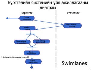
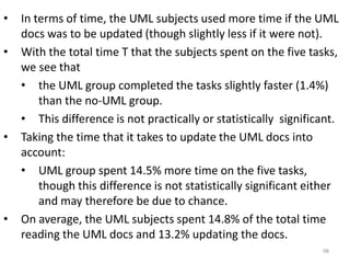
![Create curriculumSelect courses to teachCreate Бүртгэлийн системийн үйл ажиллагааны диаграмRegistrarProfessorcatalogMail catalog Place catalog to studentsin bookstoreOpen registration[ Registration time period expired ]SwimlanesClose registration37](https://image.slidesharecdn.com/oodlesson3-111006082734-phpapp02/85/Ood-lesson3-45-320.jpg)

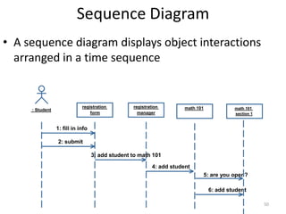
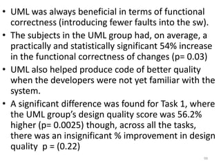
![51public class MessageReceiver{public void foo( ) { // Do something inside foo. }}public class MessageCaller{ private MessageReceivermessageReceiver; // Other Methods and Attributes of the class are declared here // The messageRecevier attribute is initialized elsewhere in // the class. public doSomething(String[] args) { // The MessageCaller invokes the foo( ) methodthis.messageReceiver.foo( ); // then waits for the method to return // before carrying on here with the rest of its work }}](https://image.slidesharecdn.com/oodlesson3-111006082734-phpapp02/85/Ood-lesson3-59-320.jpg)


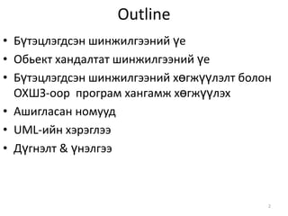
The document compares structured analysis and design (SAD) and object-oriented analysis and design (OOAD) approaches. For SAD, it discusses phases like requirements analysis using data flow diagrams and entity relationship diagrams, logical design, and physical design. For OOAD, it discusses phases like use case modeling, class diagrams, sequence diagrams, and designing the physical database and system architecture. It provides an outline of key differences and similarities between the two approaches and lists some textbooks on SAD, OOAD and the Unified Modeling Language (UML).