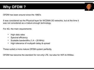
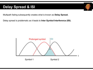
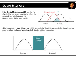
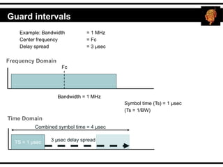
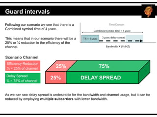
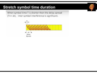
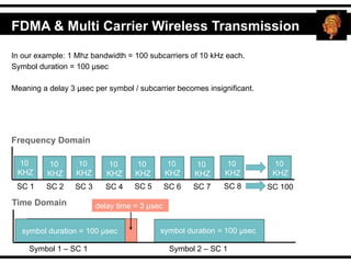
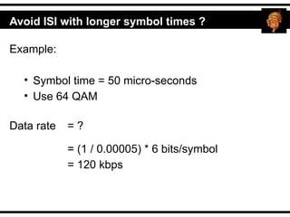
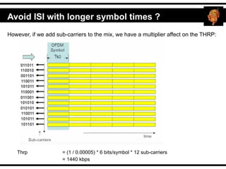
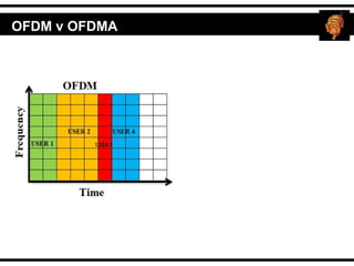
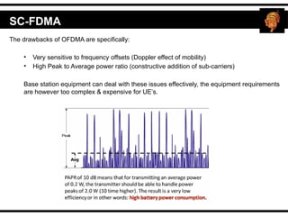
LTE Workshop #5
Covering
OFDM
Report number: OFDM
Date: 10 May 2017
OFDM has been around since the 1960’s
It was considered as the Physical layer for WCDMA 3G networks, but at the time it
was not considered as a mature enough technology.
For 4G, the main requirements:
• High data rates
• Spectral efficiency
• Scalable bandwidths (1.4 – 20 MHz)
• High tolerance of multipath delay & spread
These suited a more mature OFDM system perfectly.
OFDM has become the standard for not only LTE, but also for WiFi & WiMax.
Why OFDM ?
Analogy
Interference
First we need to understand
interference
Fixed communication path
Undisturbed communications
Wired Channel
PSTN
Multipath fading : One signal with multiple different paths between Tx & Rx
Atmospheric ducting, ionospheric reflection & refraction, object reflections
Shadow fading (flat fading) : Shadowing from obstacles affecting the wave propagation.
Path 1
Wireless Channel & Multipath Fading
Path 3
Path 2
Not all frequency components in the signal are affected equally.
Multipath fading (frequency selective)
Delay Spread & ISI
Multipath fading subsequently creates what is known as Delay Spread.
Delay spread is problematic as it leads to Inter Symbol Interference (ISI).
Delay Spread & ISI
Symbol 1 Symbol 2
t
Prolonged symbol ISI
Delay Spread & ISI
Countering interference
Guard intervals
Inter Symbol Interference (ISI) is a form of
signal distortion where a symbol overlaps the
succeeding symbol causing the
communication to be less reliable.
ISI is prevented by guard intervals, which is a period of time between symbols. Guard intervals
accommodate the late arrivals of symbols due to multipath reception.
Symbol 1 Symbol 2
t
Guard
Interval
Example: Bandwidth = 1 MHz
Center frequency = Fc
Delay spread = 3 µsec
Bandwidth = 1 MHz
Frequency Domain
Fc
Symbol time (Ts) = 1 µsec
(Ts = 1/BW)
Time Domain
TS = 1 µsec 3 µsec delay spread
Combined symbol time = 4 µsec
Guard intervals
Following our scenario we see that there is a
Combined symbol time of 4 µsec.
This means that in our scenario there will be a
25% or ¼ reduction in the efficiency of the
channel.
Scenario Channel
Efficiency Reduction
¼ = 25% of channel
DELAY SPREAD
25%
25% 75%
Delay Spread
¾ = 75% of channel
As we can see delay spread is undesirable for the bandwidth and channel usage, but it can be
reduced by employing multiple subcarriers with lower bandwidth.
Guard intervals
Stretch symbol time duration
10
KHZ
10
KHZ
In our example: 1 Mhz bandwidth = 100 subcarriers of 10 kHz each.
Symbol duration = 100 µsec
Meaning a delay 3 µsec per symbol / subcarrier becomes insignificant.
10
KHZ
10
KHZ
10
KHZ
10
KHZ
Frequency Domain
SC 1 SC 2 SC 3 SC 4 SC 7 SC 8
SC 6
SC 5 SC 100
Time Domain
Symbol 1 – SC 1 Symbol 2 – SC 1
symbol duration = 100 µsec symbol duration = 100 µsec
delay time = 3 µsec
10
KHZ
10
KHZ
10
KHZ
10
KHZ
FDMA & Multi Carrier Wireless Transmission
Avoid ISI with longer symbol times ?
Example:
• Symbol time = 50 micro-seconds
• Use 64 QAM
Data rate = ?
= (1 / 0.00005) * 6 bits/symbol
= 120 kbps
Avoid ISI with longer symbol times ?
However, if we add sub-carriers to the mix, we have a multiplier affect on the THRP:
Thrp = (1 / 0.00005) * 6 bits/symbol * 12 sub-carriers
= 1440 kbps
OFDM
Orthogonal Frequency Division
Multiplexing
OFDM v OFDMA
FDMA Concept
Data signals
Data
modulation &
Increase of
Bandwidth
1 2 3
1 2 3
Modulated SC
separated by
guard
intervals in
the frequency
domains
Guard Interval Guard Interval
SC frequency 1 SC frequency 2 SC frequency 3
channels divided into equal bandwidth spectrums
S
C
1
S
C
2
S
C
3
O (Orthogonal) FDM
Orthogonality in a OFDM system takes place when the peak of a subcarrier (SC) is reached and
the other subcarriers (SC) contribution is zero.
SC 1 SC 2 SC 3
Peaks of subcarriers (SC)
0
Spectrum
Peak
SC 3
S
C
1
S
C
2
S
C
3
S
C
4
S
C
5
S
C
6
When subcarriers (SC) 1 – 6 are at their peaks there is no interference from the other subcarriers
(SC) due do them being orthogonal.
O (Orthogonal) FDM & Bandwidth
Because the subcarriers are orthogonal they can use the same bandwidth without any
interference.
0
Spectrum
Peak
S
C
1
S
C
2
S
C
3
S
C
4
S
C
5
S
C
6
Sam
e
Bandwidth
usage
Sam
e
Bandwidth
usage Sam
e
Bandwidth
usage
When subcarriers (SC) 1 – 6 are at their peaks there is no interference from the other subcarriers
(SC) due do them being orthogonal and this allows them to use the same bandwidth.
G
U
A
R
D
G
U
A
R
D
G
U
A
R
D
G
U
A
R
D
G
U
A
R
D
G
U
A
R
D
OFDM compared to FDMA
FDMA Spectrum
OFDM Spectrum
Bandwidth
Bandwidth
Frequency
Frequency
Saved Bandwidth
S
C
1
S
C
2
S
C
3
S
C
4
S
C
5
S
C
6
S
C
7
S
C
1
S
C
2
S
C
3
S
C
4
S
C
5
S
C
6
S
C
7
Orthogonal subcarriers
OFDM - Subcarrier Separation around the DC
The subcarriers are then separated on either side of the DC in multiples of 15KHZ.
Direct Conversion (DC) is a null subcarrier which is allocated to have a equal frequency to that of
the RF center frequency of the transmitting station.
S
C
S
C
S
C
S
C
15 KHZ 15 KHZ
DC
DC - SC
Channel
Bandwidth
Usable
Bandwidth
Subcarrier
count
1.4 MHZ 1.08 MHZ 72
3 MHZ 2.7 MHZ 180
5 MHZ 4.5 MHZ 300
10 MHZ 9 HMZ 600
LTE can support variable channel bandwidth as shown below please note that as
bandwidth increases so does the number of subcarriers.
OFDM - Subcarrier Separation around the DC
LTE bandwidth Table.
Calculation
1MHZ = 1000 KHZ
1.08 MHZ x 1000 = = 72 SC
2.7 MHZ x 1000 = = 180 SC
4.5 MHZ x 1000 = = 300 SC
9 MHZ x 1000 = = 600 SC
For an example lets take LTE bandwidth of 5 MHZ.
OFDM - Subcarrier Separation around the DC
Channel
Bandwidth
Usable
Bandwidth
Usable
Bandwidth In
Number Of
Subcarriers
5 MHZ 4.5 MHZ 300
Calculation
1MHZ = 1000 KHZ
4.5 MHZ x 1000 = = 300 SC
Remember that the DC is also a subcarrier and there is 0.5 MHZ used for guard bands in the form
of subcarriers.
5 MHZ = 5000 KHZ
Number of SC used for guard band = = 333 SC
Number of SC used for guard band = 333 – 1 (DC subcarrier) – 300 (Usable subcarriers)
Number of SC used for guard band =
Number of SC used for guard band = 16 SC either side of the DC
5 MHZ = 5000 KHZ = 333 SC
DC = 1 SC (15 KHZ)
Guard band
0.5 MHZ = 500 KHZ = 32 SC = 16 SC on each side of the DC
D
C
15
KHZ
SC
30
KHZ
SC
45
KHZ
SC
60
KHZ
SC
75
KHZ
SC
90
KHZ
SC
105
KHZ
SC
120
KHZ
SC
135
KHZ
SC
150
KHZ
SC
165
KHZ
SC
180
KHZ
SC
195
KHZ
SC
…
2250
KHZ
…
–
2250
KHZ
-
195
KHZ
SC
-
180
KHZ
SC
-
165
KHZ
SC
-
150
KHZ
SC
-
135
KHZ
SC
-
120
KHZ
SC
-
105
KHZ
SC
-
90
KHZ
SC
-
75
KHZ
SC
-
60
KHZ
SC
-
45
KHZ
SC
-
30
KHZ
SC
-
15
KHZ
SC
OFDM - Subcarrier Separation around the DC
Please note that there is a total of 150 usable subcarriers on either
side of the DC so the complete usable KHZ for 5 MHZ is 2250 KHZ
on either side of the DC
150 Usable subcarriers of -15 KHZ each 150 Usable subcarriers of 15 KHZ each
G
U
A
R
D
G
U
A
R
D
Recall that we are using OFDM so all these subcarriers are orthogonal. Furthermore the
use of negative frequency is needed because the subcarriers are transmitted below the
radio carrier.
The drawbacks of OFDMA are specifically:
• Very sensitive to frequency offsets (Doppler effect of mobility)
• High Peak to Average power ratio (constructive addition of sub-carriers)
Base station equipment can deal with these issues effectively, the equipment requirements
are however too complex & expensive for UE’s.
SC-FDMA
It is for this reason that the LTE Uplink uses SC-FDMA on the physical layer – here we use a
single carrier as opposed to N * Sub-carriers.
SC-FDMA
Time/frequency resources dynamically allocated:
Resource allocation example

OFDM basics and trouble shooting technique

  • 1.
    LTE Workshop #5 Covering OFDM Reportnumber: OFDM Date: 10 May 2017
  • 2.
    OFDM has beenaround since the 1960’s It was considered as the Physical layer for WCDMA 3G networks, but at the time it was not considered as a mature enough technology. For 4G, the main requirements: • High data rates • Spectral efficiency • Scalable bandwidths (1.4 – 20 MHz) • High tolerance of multipath delay & spread These suited a more mature OFDM system perfectly. OFDM has become the standard for not only LTE, but also for WiFi & WiMax. Why OFDM ?
  • 3.
  • 4.
    Interference First we needto understand interference
  • 5.
    Fixed communication path Undisturbedcommunications Wired Channel PSTN
  • 6.
    Multipath fading :One signal with multiple different paths between Tx & Rx Atmospheric ducting, ionospheric reflection & refraction, object reflections Shadow fading (flat fading) : Shadowing from obstacles affecting the wave propagation. Path 1 Wireless Channel & Multipath Fading Path 3 Path 2
  • 7.
    Not all frequencycomponents in the signal are affected equally. Multipath fading (frequency selective)
  • 8.
  • 9.
    Multipath fading subsequentlycreates what is known as Delay Spread. Delay spread is problematic as it leads to Inter Symbol Interference (ISI). Delay Spread & ISI Symbol 1 Symbol 2 t Prolonged symbol ISI
  • 10.
  • 11.
  • 12.
    Guard intervals Inter SymbolInterference (ISI) is a form of signal distortion where a symbol overlaps the succeeding symbol causing the communication to be less reliable. ISI is prevented by guard intervals, which is a period of time between symbols. Guard intervals accommodate the late arrivals of symbols due to multipath reception. Symbol 1 Symbol 2 t Guard Interval
  • 13.
    Example: Bandwidth =1 MHz Center frequency = Fc Delay spread = 3 µsec Bandwidth = 1 MHz Frequency Domain Fc Symbol time (Ts) = 1 µsec (Ts = 1/BW) Time Domain TS = 1 µsec 3 µsec delay spread Combined symbol time = 4 µsec Guard intervals
  • 14.
    Following our scenariowe see that there is a Combined symbol time of 4 µsec. This means that in our scenario there will be a 25% or ¼ reduction in the efficiency of the channel. Scenario Channel Efficiency Reduction ¼ = 25% of channel DELAY SPREAD 25% 25% 75% Delay Spread ¾ = 75% of channel As we can see delay spread is undesirable for the bandwidth and channel usage, but it can be reduced by employing multiple subcarriers with lower bandwidth. Guard intervals
  • 15.
  • 16.
    10 KHZ 10 KHZ In our example:1 Mhz bandwidth = 100 subcarriers of 10 kHz each. Symbol duration = 100 µsec Meaning a delay 3 µsec per symbol / subcarrier becomes insignificant. 10 KHZ 10 KHZ 10 KHZ 10 KHZ Frequency Domain SC 1 SC 2 SC 3 SC 4 SC 7 SC 8 SC 6 SC 5 SC 100 Time Domain Symbol 1 – SC 1 Symbol 2 – SC 1 symbol duration = 100 µsec symbol duration = 100 µsec delay time = 3 µsec 10 KHZ 10 KHZ 10 KHZ 10 KHZ FDMA & Multi Carrier Wireless Transmission
  • 17.
    Avoid ISI withlonger symbol times ? Example: • Symbol time = 50 micro-seconds • Use 64 QAM Data rate = ? = (1 / 0.00005) * 6 bits/symbol = 120 kbps
  • 18.
    Avoid ISI withlonger symbol times ? However, if we add sub-carriers to the mix, we have a multiplier affect on the THRP: Thrp = (1 / 0.00005) * 6 bits/symbol * 12 sub-carriers = 1440 kbps
  • 19.
  • 20.
  • 21.
    FDMA Concept Data signals Data modulation& Increase of Bandwidth 1 2 3 1 2 3 Modulated SC separated by guard intervals in the frequency domains Guard Interval Guard Interval SC frequency 1 SC frequency 2 SC frequency 3 channels divided into equal bandwidth spectrums S C 1 S C 2 S C 3
  • 22.
    O (Orthogonal) FDM Orthogonalityin a OFDM system takes place when the peak of a subcarrier (SC) is reached and the other subcarriers (SC) contribution is zero. SC 1 SC 2 SC 3 Peaks of subcarriers (SC) 0 Spectrum Peak SC 3 S C 1 S C 2 S C 3 S C 4 S C 5 S C 6 When subcarriers (SC) 1 – 6 are at their peaks there is no interference from the other subcarriers (SC) due do them being orthogonal.
  • 23.
    O (Orthogonal) FDM& Bandwidth Because the subcarriers are orthogonal they can use the same bandwidth without any interference. 0 Spectrum Peak S C 1 S C 2 S C 3 S C 4 S C 5 S C 6 Sam e Bandwidth usage Sam e Bandwidth usage Sam e Bandwidth usage When subcarriers (SC) 1 – 6 are at their peaks there is no interference from the other subcarriers (SC) due do them being orthogonal and this allows them to use the same bandwidth.
  • 24.
    G U A R D G U A R D G U A R D G U A R D G U A R D G U A R D OFDM compared toFDMA FDMA Spectrum OFDM Spectrum Bandwidth Bandwidth Frequency Frequency Saved Bandwidth S C 1 S C 2 S C 3 S C 4 S C 5 S C 6 S C 7 S C 1 S C 2 S C 3 S C 4 S C 5 S C 6 S C 7 Orthogonal subcarriers
  • 25.
    OFDM - SubcarrierSeparation around the DC The subcarriers are then separated on either side of the DC in multiples of 15KHZ. Direct Conversion (DC) is a null subcarrier which is allocated to have a equal frequency to that of the RF center frequency of the transmitting station. S C S C S C S C 15 KHZ 15 KHZ DC DC - SC
  • 26.
    Channel Bandwidth Usable Bandwidth Subcarrier count 1.4 MHZ 1.08MHZ 72 3 MHZ 2.7 MHZ 180 5 MHZ 4.5 MHZ 300 10 MHZ 9 HMZ 600 LTE can support variable channel bandwidth as shown below please note that as bandwidth increases so does the number of subcarriers. OFDM - Subcarrier Separation around the DC LTE bandwidth Table. Calculation 1MHZ = 1000 KHZ 1.08 MHZ x 1000 = = 72 SC 2.7 MHZ x 1000 = = 180 SC 4.5 MHZ x 1000 = = 300 SC 9 MHZ x 1000 = = 600 SC
  • 27.
    For an examplelets take LTE bandwidth of 5 MHZ. OFDM - Subcarrier Separation around the DC Channel Bandwidth Usable Bandwidth Usable Bandwidth In Number Of Subcarriers 5 MHZ 4.5 MHZ 300 Calculation 1MHZ = 1000 KHZ 4.5 MHZ x 1000 = = 300 SC Remember that the DC is also a subcarrier and there is 0.5 MHZ used for guard bands in the form of subcarriers. 5 MHZ = 5000 KHZ Number of SC used for guard band = = 333 SC Number of SC used for guard band = 333 – 1 (DC subcarrier) – 300 (Usable subcarriers) Number of SC used for guard band = Number of SC used for guard band = 16 SC either side of the DC
  • 28.
    5 MHZ =5000 KHZ = 333 SC DC = 1 SC (15 KHZ) Guard band 0.5 MHZ = 500 KHZ = 32 SC = 16 SC on each side of the DC D C 15 KHZ SC 30 KHZ SC 45 KHZ SC 60 KHZ SC 75 KHZ SC 90 KHZ SC 105 KHZ SC 120 KHZ SC 135 KHZ SC 150 KHZ SC 165 KHZ SC 180 KHZ SC 195 KHZ SC … 2250 KHZ … – 2250 KHZ - 195 KHZ SC - 180 KHZ SC - 165 KHZ SC - 150 KHZ SC - 135 KHZ SC - 120 KHZ SC - 105 KHZ SC - 90 KHZ SC - 75 KHZ SC - 60 KHZ SC - 45 KHZ SC - 30 KHZ SC - 15 KHZ SC OFDM - Subcarrier Separation around the DC Please note that there is a total of 150 usable subcarriers on either side of the DC so the complete usable KHZ for 5 MHZ is 2250 KHZ on either side of the DC 150 Usable subcarriers of -15 KHZ each 150 Usable subcarriers of 15 KHZ each G U A R D G U A R D Recall that we are using OFDM so all these subcarriers are orthogonal. Furthermore the use of negative frequency is needed because the subcarriers are transmitted below the radio carrier.
  • 29.
    The drawbacks ofOFDMA are specifically: • Very sensitive to frequency offsets (Doppler effect of mobility) • High Peak to Average power ratio (constructive addition of sub-carriers) Base station equipment can deal with these issues effectively, the equipment requirements are however too complex & expensive for UE’s. SC-FDMA
  • 30.
    It is forthis reason that the LTE Uplink uses SC-FDMA on the physical layer – here we use a single carrier as opposed to N * Sub-carriers. SC-FDMA
  • 31.
    Time/frequency resources dynamicallyallocated: Resource allocation example