
Recommended
More Related Content
More from dfujjsefkemm
More from dfujjsefkemm (20)
Recently uploaded
Recently uploaded (20)
New holland tg305 tractor service repair manual
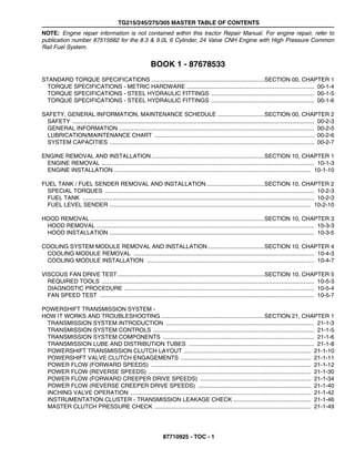
- 1. TG215/245/275/305 MASTER TABLE OF CONTENTS 87710925 - TOC - 1 NOTE: Engine repair information is not contained within this tractor Repair Manual. For engine repair, refer to publication number 87515682 for the 8.3 & 9.0L 6 Cylinder, 24 Valve CNH Engine with High Pressure Common Rail Fuel System. BOOK 1 - 87678533 STANDARD TORQUE SPECIFICATIONS ......................................................................SECTION 00, CHAPTER 1 TORQUE SPECIFICATIONS - METRIC HARDWARE ............................................................................... 00-1-4 TORQUE SPECIFICATIONS - STEEL HYDRAULIC FITTINGS ................................................................ 00-1-5 TORQUE SPECIFICATIONS - STEEL HYDRAULIC FITTINGS ................................................................ 00-1-6 SAFETY, GENERAL INFORMATION, MAINTENANCE SCHEDULE .............................SECTION 00, CHAPTER 2 SAFETY ...................................................................................................................................................... 00-2-3 GENERAL INFORMATION ......................................................................................................................... 00-2-5 LUBRICATION/MAINTENANCE CHART ................................................................................................... 00-2-6 SYSTEM CAPACITIES ............................................................................................................................... 00-2-7 ENGINE REMOVAL AND INSTALLATION......................................................................SECTION 10, CHAPTER 1 ENGINE REMOVAL .................................................................................................................................... 10-1-3 ENGINE INSTALLATION .......................................................................................................................... 10-1-10 FUEL TANK / FUEL SENDER REMOVAL AND INSTALLATION....................................SECTION 10, CHAPTER 2 SPECIAL TORQUES .................................................................................................................................. 10-2-3 FUEL TANK ................................................................................................................................................ 10-2-3 FUEL LEVEL SENDER ............................................................................................................................. 10-2-10 HOOD REMOVAL ............................................................................................................SECTION 10, CHAPTER 3 HOOD REMOVAL ....................................................................................................................................... 10-3-3 HOOD INSTALLATION ............................................................................................................................... 10-3-5 COOLING SYSTEM MODULE REMOVAL AND INSTALLATION ...................................SECTION 10, CHAPTER 4 COOLING MODULE REMOVAL ................................................................................................................ 10-4-3 COOLING MODULE INSTALLATION ........................................................................................................ 10-4-7 VISCOUS FAN DRIVE TEST...........................................................................................SECTION 10, CHAPTER 5 REQUIRED TOOLS .................................................................................................................................... 10-5-3 DIAGNOSTIC PROCEDURE ...................................................................................................................... 10-5-4 FAN SPEED TEST ..................................................................................................................................... 10-5-7 POWERSHIFT TRANSMISSION SYSTEM - HOW IT WORKS AND TROUBLESHOOTING ................................................................SECTION 21, CHAPTER 1 TRANSMISSION SYSTEM INTRODUCTION ............................................................................................ 21-1-3 TRANSMISSION SYSTEM CONTROLS .................................................................................................... 21-1-5 TRANSMISSION SYSTEM COMPONENTS .............................................................................................. 21-1-6 TRANSMISSION LUBE AND DISTRIBUTION TUBES .............................................................................. 21-1-8 POWERSHIFT TRANSMISSION CLUTCH LAYOUT ............................................................................... 21-1-10 POWERSHIFT VALVE CLUTCH ENGAGEMENTS ................................................................................. 21-1-11 POWER FLOW (FORWARD SPEEDS) ................................................................................................... 21-1-12 POWER FLOW (REVERSE SPEEDS) ..................................................................................................... 21-1-30 POWER FLOW (FORWARD CREEPER DRIVE SPEEDS) ..................................................................... 21-1-34 POWER FLOW (REVERSE CREEPER DRIVE SPEEDS) ...................................................................... 21-1-40 INCHING VALVE OPERATION ................................................................................................................ 21-1-42 INSTRUMENTATION CLUSTER - TRANSMISSION LEAKAGE CHECK ................................................ 21-1-46 MASTER CLUTCH PRESSURE CHECK ................................................................................................. 21-1-49
- 2. TG215/245/275/305 MASTER TABLE OF CONTENTS 87710925 - TOC - 2 FRONT FRAME TO SPEED TRANSMISSION SPLIT.....................................................SECTION 21, CHAPTER 2 SPECIAL TOOLS ........................................................................................................................................ 21-2-3 SPECIAL TORQUES .................................................................................................................................. 21-2-3 FRONT FRAME TO SPEED TRANSMISSION SPLIT ............................................................................... 21-2-4 SPEED TO RANGE TRANSMISSION SPLIT ..................................................................SECTION 21, CHAPTER 3 SPECIAL TOOLS ........................................................................................................................................ 21-3-3 SPECIAL TORQUES .................................................................................................................................. 21-3-3 SPEED TO RANGE TRANSMISSION SPLIT ............................................................................................. 21-3-4 Removal .................................................................................................................................................... 21-3-4 Installation ................................................................................................................................................. 21-3-7 SPEED TRANSMISSION.................................................................................................SECTION 21, CHAPTER 4 SPECIFICATIONS ...................................................................................................................................... 21-4-4 SPECIAL TORQUES .................................................................................................................................. 21-4-4 TROUBLESHOOTING AFTER SPEED TRANSMISSION REPAIR ........................................................... 21-4-4 SPECIAL TOOLS ........................................................................................................................................ 21-4-5 SPEED TRANSMISSION WITH CREEP OPTION ..................................................................................... 21-4-6 ASSEMBLING THE COUNTERSHAFT WITH CREEPER SPEED CLUTCH .......................................... 21-4-14 TRANSMISSION ASSEMBLY WITH CREEP OPTION ............................................................................ 21-4-78 TRANSMISSION ASSEMBLY WITHOUT CREEP OPTION .................................................................... 21-4-80 RANGE TRANSMISSION TO REAR FRAME SPLIT.......................................................SECTION 21, CHAPTER 5 SPECIAL TOOLS ........................................................................................................................................ 21-5-3 SPECIAL TORQUES .................................................................................................................................. 21-5-3 RANGE TRANSMISSION TO REAR FRAME SPLIT ................................................................................. 21-5-4 Disassembly .............................................................................................................................................. 21-5-4 Assembly ................................................................................................................................................... 21-5-7 RANGE TRANSMISSION ................................................................................................SECTION 21, CHAPTER 6 SPECIFICATIONS ...................................................................................................................................... 21-6-3 TROUBLESHOOTING AFTER RANGE TRANSMISSION REPAIR .......................................................... 21-6-3 SPECIAL TORQUES .................................................................................................................................. 21-6-3 SPECIAL TOOLS ........................................................................................................................................ 21-6-4 RANGE TRANSMISSION ........................................................................................................................... 21-6-5 Removing the Shaft Master Clutch ........................................................................................................... 21-6-5 Removing the Input Shaft, Countershaft and Front Wheel Drive (FWD) / Park Brake Assembly ............. 21-6-7 Disassembly of the Master Clutch ........................................................................................................... 21-6-12 Exploded View of the Master Clutch ....................................................................................................... 21-6-14 Assembly of the Master Clutch ............................................................................................................... 21-6-15 Disassembly of the Range Transmission Input Shaft ............................................................................. 21-6-16 Exploded View of the Range Transmission Input Shaft .......................................................................... 21-6-22 Assembly of the Range Transmission Input Shaft .................................................................................. 21-6-23 Cross-Section of Input Shaft ................................................................................................................... 21-6-32 Disassembly of the Range Transmission Countershaft .......................................................................... 21-6-33 Exploded View of the Range Transmission Countershaft ....................................................................... 21-6-37 Assembly of the Range Transmission Countershaft ............................................................................... 21-6-38 Front Wheel Drive (FWD) - Emergency Brake Disassembly .................................................................. 21-6-45 Exploded View of FWD and Emergency Brake ....................................................................................... 21-6-51 Assembly of the FWD / Emergency Brake .............................................................................................. 21-6-52 Exploded View of the Range Transmission Countershaft, Input Shaft, and FWD Input Shaft ................ 21-6-66 Installing the Range Transmission Countershaft, Input Shaft, and FWD Input Shaft into the Range Transmission Housing ................................................................................................................. 21-6-67 SETTING THE END PLAY OF THE RANGE TRANSMISSION COUNTERSHAFT AND INPUT SHAFT 21-6-73 Installing the Range Input Master Clutch ................................................................................................ 21-6-75
- 3. TG215/245/275/305 MASTER TABLE OF CONTENTS 87710925 - TOC - 3 TRANSMISSION CONTROL VALVES AND INCHING VALVE .......................................SECTION 21, CHAPTER 7 SPECIAL TORQUES .................................................................................................................................. 21-7-3 POWERSHIFT TRANSMISSION CONTROL VALVES .............................................................................. 21-7-3 TRANSMISSION CONTROL VALVE CONFIGURATION .......................................................................... 21-7-4 INCHING VALVE ...................................................................................................................................... 21-7-15 REAR FRAME ..................................................................................................................SECTION 21, CHAPTER 8 SPECIFICATIONS ...................................................................................................................................... 21-8-3 SPECIAL TORQUES .................................................................................................................................. 21-8-3 SPECIAL TOOLS ........................................................................................................................................ 21-8-3 DIFFERENTIAL .......................................................................................................................................... 21-8-4 Removal .................................................................................................................................................... 21-8-4 Disassembly ............................................................................................................................................ 21-8-10 PINION SHAFT ......................................................................................................................................... 21-8-15 Removal and Disassembly ...................................................................................................................... 21-8-15 Assembly and Installation ....................................................................................................................... 21-8-18 HEAVY DUTY PINION SHAFT................................................................................................................... 21-8-25 Removal and Disassembly........................................................................................................................ 21-8-25 Assembly and Installation ......................................................................................................................... 21-8-27 DIFFERENTIAL ASSEMBLY .................................................................................................................... 21-8-33 DIFFERENTIAL INSTALLATION .............................................................................................................. 21-8-38 ADJUSTING THE DIFFERENTIAL PRELOAD ......................................................................................... 21-8-45 ADJUSTING THE RING AND PINION BACKLASH ................................................................................. 21-8-47 BEVEL PINION AND GEAR TOOTH CONTACT CHECK ........................................................................ 21-8-48 HYDRAULIC PUMP DRIVE .............................................................................................SECTION 21, CHAPTER 9 SPECIAL TORQUES .................................................................................................................................. 21-9-3 SPECIFICATIONS ...................................................................................................................................... 21-9-3 PUMP DRIVE .............................................................................................................................................. 21-9-3 Removal .................................................................................................................................................... 21-9-3 Disassembly .............................................................................................................................................. 21-9-4 Assembly ................................................................................................................................................... 21-9-7 Installation ............................................................................................................................................... 21-9-12 BOOK 2 - 87689442 FRONT WHEEL DRIVE CONTROL SYSTEM - HOW IT WORKS ..................................SECTION 25, CHAPTER 1 FRONT WHEEL DRIVE (FWD) .................................................................................................................. 25-1-3 ELECTRONIC FRONT WHEEL DRIVE (FWD) CONTROL ....................................................................... 25-1-5 FRONT WHEEL DRIVE (FWD) CONTROL MODES ................................................................................. 25-1-7 FRONT WHEEL DRIVE (FWD) FUNCTIONAL TESTS .............................................................................. 25-1-8 TROUBLESHOOTING .............................................................................................................................. 25-1-10 DIFFERENTIAL LOCK CONTROL SYSTEM - HOW IT WORKS ....................................SECTION 25, CHAPTER 2 DIFFERENTIAL LOCK ................................................................................................................................ 25-2-3 ELECTRONIC DIFFERENTIAL LOCK CONTROL ..................................................................................... 25-2-5 DIFFERENTIAL LOCK CONTROL MODES ............................................................................................... 25-2-7 DIFFERENTIAL LOCK CONTROL ............................................................................................................. 25-2-8 DIFFERENTIAL LOCK FUNCTIONAL TESTS ........................................................................................... 25-2-9 TROUBLESHOOTING .............................................................................................................................. 25-2-12 TROUBLESHOOTING .............................................................................................................................. 25-2-14 PTO/DIFFERENTIAL LOCK VALVE CIRCUIT ......................................................................................... 25-2-15 FRONT WHEEL DRIVE OUTPUT SHAFT.......................................................................SECTION 25, CHAPTER 3 SPECIAL TORQUES .................................................................................................................................. 25-3-3 FWD OUTPUT SHAFT ............................................................................................................................... 25-3-4 FWD Output Shaft Removal ...................................................................................................................... 25-3-4
- 4. TG215/245/275/305 MASTER TABLE OF CONTENTS 87710925 - TOC - 4 FWD Output Shaft Disassembly ............................................................................................................... 25-3-5 FWD Output Shaft Assembly .................................................................................................................... 25-3-9 FRONT WHEEL DRIVE DRIVE SHAFT...........................................................................SECTION 25, CHAPTER 4 SPECIAL TORQUES .................................................................................................................................. 25-4-3 FWD DRIVE SHAFT ................................................................................................................................... 25-4-4 SUSPENSION FWD AXLE SYSTEM - HOW IT WORKS AND TROUBLESHOOTING ..SECTION 25, CHAPTER 5 SUSPENDED FWD AXLE OPERATION ................................................................................................... 25-5-3 SUSPENDED MFD AXLE- CALIBRATION MODE .................................................................................... 25-5-9 ERROR TABLE ......................................................................................................................................... 25-5-11 SUSPENDED FWD AXLE- MANUAL OPERATION MODE (TEST MODE) ............................................ 25-5-13 SUSPENDED FWD AXLE- DEMONSTRATION MODE .......................................................................... 25-5-16 SUSPENSION FWD AXLE REMOVAL............................................................................SECTION 25, CHAPTER 6 SUSPENDED FWD AXLE .......................................................................................................................... 25-6-3 Removal .................................................................................................................................................... 25-6-3 Installation ................................................................................................................................................. 25-6-5 SUPERSTEER AXLE REMOVAL AND INSTALLATION .................................................SECTION 25, CHAPTER 7 SPECIAL TORQUES .................................................................................................................................. 25-7-3 SPECIAL TOOLS ........................................................................................................................................ 25-7-3 FRONT AXLE REMOVAL ........................................................................................................................... 25-7-4 FRONT AXLE INSTALLATION ................................................................................................................... 25-7-7 LIMITED SLIP FWD DIFFERENTIAL...............................................................................SECTION 25, CHAPTER 8 SPECIFICATIONS ...................................................................................................................................... 25-8-2 SPECIAL TORQUES .................................................................................................................................. 25-8-2 SPECIAL TOOLS ........................................................................................................................................ 25-8-2 12 BOLT AXLE .......................................................................................................................................... 25-8-2 DIFFERENTIAL CARRIER ASSEMBLY REMOVAL .................................................................................. 25-8-3 DIFFERENTIAL DISASSEMBLY ................................................................................................................ 25-8-4 Pinion Disassembly ................................................................................................................................... 25-8-8 DIFFERENTIAL ASSEMBLY .................................................................................................................... 25-8-11 DIFFERENTIAL CARRIER ASSEMBLY ................................................................................................... 25-8-15 Pinion Position and Assembly ................................................................................................................. 25-8-15 Shim Pack Thickness Chart .................................................................................................................. 25-8-16 Setting The Pinion Depth ........................................................................................................................ 25-8-17 Adjusting Bearing Preload ....................................................................................................................... 25-8-20 DIFFERENTIAL INSTALLATION .............................................................................................................. 25-8-22 Checking Backlash .................................................................................................................................. 25-8-23 Ring Gear and Pinion Tooth Pattern Interpretation ................................................................................. 25-8-25 Installation of Carrier Assembly to Axle Housing .................................................................................... 25-8-27 LOCKING FWD DIFFERENTIAL......................................................................................SECTION 25, CHAPTER 9 SPECIFICATIONS ...................................................................................................................................... 25-9-3 SPECIAL TORQUES .................................................................................................................................. 25-9-3 SPECIAL TOOLS ........................................................................................................................................ 25-9-3 REMOVAL OF THE FRONT DIFFERENTIAL CARRIER ASSEMBLY ....................................................... 25-9-4 REMOVAL OF THE FRONT DIFFERENTIAL FROM THE CARRIER HOUSING ..................................... 25-9-5 DISASSEMBLY OF THE DIFFERENTIAL .................................................................................................. 25-9-7 PINION DISASSEMBLY ............................................................................................................................. 25-9-9 ASSEMBLY OF THE DIFFERENTIAL ...................................................................................................... 25-9-12 DIFFERENTIAL CARRIER ASSEMBLY ................................................................................................... 25-9-16 SETTING THE PINION DEPTH ................................................................................................................ 25-9-18 ADJUSTING BEARING PRELOAD .......................................................................................................... 25-9-21 DIFFERENTIAL INSTALLATION .............................................................................................................. 25-9-23
- 5. TG215/245/275/305 MASTER TABLE OF CONTENTS 87710925 - TOC - 5 FWD PLANETARY HUB, STEERING KNUCKLE AND AXLE DRIVE SHAFT ..............SECTION 25, CHAPTER 10 SPECIFICATIONS .................................................................................................................................... 25-10-3 SPECIAL TORQUES ................................................................................................................................ 25-10-3 SPECIAL TOOLS ...................................................................................................................................... 25-10-3 PLANETARY HUB DISASSEMBLY .......................................................................................................... 25-10-4 STEERING KNUCKLE AND KINGPIN DISASSEMBLY ........................................................................... 25-10-9 AXLE DRIVE SHAFT DISASSEMBLY .................................................................................................... 25-10-13 AXLE SHAFT ASSEMBLY ...................................................................................................................... 25-10-14 KINGPIN ASSEMBLY ............................................................................................................................. 25-10-16 STEERING KNUCKLE ASSEMBLY ....................................................................................................... 25-10-20 PLANETARY HUB ASSEMBLY .............................................................................................................. 25-10-25 Ten Bolt Axle Only ................................................................................................................................ 25-10-30 Twelve Bolt Axle Only ........................................................................................................................... 25-10-34 All Axles ................................................................................................................................................ 25-10-39 SUSPENSION FWD AXLE.............................................................................................SECTION 25, CHAPTER 11 SPECIAL TORQUES ................................................................................................................................ 25-11-2 SUSPENSION FWD AXLE ....................................................................................................................... 25-11-3 Disassembly ............................................................................................................................................ 25-11-3 Assembly ............................................................................................................................................... 25-11-13 Position Sensor Adjustment .................................................................................................................. 25-11-25 SUPERSTEER AXLE VERTICAL CONTROL LINKAGE ...............................................SECTION 25, CHAPTER 12 SPECIAL TORQUES ................................................................................................................................ 25-12-3 VERTICAL LINK DISASSEMBLY AND REPAIR ...................................................................................... 25-12-3 Vertical Link Removal ............................................................................................................................. 25-12-3 Roller Replacement ................................................................................................................................. 25-12-4 Articulation Bearing Removal and Installation ......................................................................................... 25-12-5 REAR AXLE AND PLANETARIES...................................................................................SECTION 27, CHAPTER 1 SPECIAL TOOLS ........................................................................................................................................ 27-1-3 SPECIAL TORQUES .................................................................................................................................. 27-1-5 SPECIFICATIONS ...................................................................................................................................... 27-1-5 GENERAL INFORMATION ......................................................................................................................... 27-1-5 REAR AXLE ................................................................................................................................................ 27-1-6 AXLE HOUSING DISASSEMBLY ............................................................................................................... 27-1-9 PLANETARY DISASSEMBLY .................................................................................................................. 27-1-11 DIFFERENTIAL CARRIER SEAL REPLACEMENT ................................................................................. 27-1-13 PLANETARY ASSEMBLY - THREE PIN .................................................................................................. 27-1-14 PLANETARY ASSEMBLY - FOUR PIN .................................................................................................... 27-1-15 AXLE HOUSING ASSEMBLY ................................................................................................................... 27-1-18 HOW TO DETERMINE RAM PRESSURE ............................................................................................... 27-1-23 AXLE INSTALLATION .............................................................................................................................. 27-1-26 AXLE SEAL WEAR SLEEVE INSTALLATION (4-Inch Axle Only) ........................................................... 27-1-30 POWER TAKE OFF CONTROL SYSTEM - HOW IT WORKS ........................................SECTION 31, CHAPTER 1 POWER TAKE OFF .................................................................................................................................... 31-1-3 ELECTRONIC PTO CONTROL .................................................................................................................. 31-1-4 PTO SYSTEM CONTROL .......................................................................................................................... 31-1-7 PTO CONTROL MODES ............................................................................................................................ 31-1-8 PTO VALVE OIL SUPPLY ........................................................................................................................ 31-1-10 PTO DIFFERENTIAL LOCK VALVE ......................................................................................................... 31-1-11 TROUBLESHOOTING .............................................................................................................................. 31-1-12
- 6. TG215/245/275/305 MASTER TABLE OF CONTENTS 87710925 - TOC - 6 PTO CLUTCH ASSEMBLY - SINGLE, REVERSIBLE AND DUAL SPEED.....................SECTION 31, CHAPTER 2 (NOTE: Book 2A contains updated information in Section 31, Chapter 2. Use the information in Book 2A in place of this original chapter.) BRAKE VALVE.................................................................................................................SECTION 33, CHAPTER 1 SPECIAL TORQUES .................................................................................................................................. 33-2-2 BRAKE VALVE ........................................................................................................................................... 33-2-3 Removal .................................................................................................................................................... 33-2-3 Disassembly .............................................................................................................................................. 33-2-4 Assembly ................................................................................................................................................... 33-2-6 Installation ................................................................................................................................................. 33-2-8 BRAKE CYLINDERS........................................................................................................SECTION 33, CHAPTER 2 SPECIAL TORQUES .................................................................................................................................. 33-2-3 SPECIFICATIONS ...................................................................................................................................... 33-2-3 BRAKE CYLINDERS .................................................................................................................................. 33-2-3 Disassembly .............................................................................................................................................. 33-2-3 Assembly ................................................................................................................................................... 33-2-5 BOOK 2A - 87710926 PTO CLUTCH ASSEMBLY - SINGLE, REVERSIBLE AND DUAL SPEED.....................SECTION 31, CHAPTER 2 SPECIAL TOOLS ........................................................................................................................................ 31-2-3 SPECIAL TORQUES .................................................................................................................................. 31-2-3 PTO CLUTCH ASSEMBLY ......................................................................................................................... 31-2-4 General ..................................................................................................................................................... 31-2-4 PTO CLUTCH SERVICE ............................................................................................................................ 31-2-4 Removal .................................................................................................................................................... 31-2-4 Disassembly .............................................................................................................................................. 31-2-6 Assembly ................................................................................................................................................. 31-2-16 Exploded View of PTO Clutch ............................................................................................................... 31-2-16 Cross Section of PTO Clutch and Output Shaft Assembly .................................................................... 31-2-33 SINGLE SPEED REVERSIBLE SHAFT PTO ........................................................................................... 31-2-34 Disassembly ............................................................................................................................................ 31-2-34 Assembly ................................................................................................................................................. 31-2-37 Exploded View of PTO Output Shaft and Driven Gear Assembly ......................................................... 31-2-37 SINGLE SPEED REVERSIBLE SHAFT PTO DRIVEN GEAR ................................................................. 31-2-41 Removal .................................................................................................................................................. 31-2-41 Assembly ................................................................................................................................................. 31-2-43 Reversible PTO Output Shaft Bearing Adjustment ................................................................................. 31-2-45 SINGLE SPEED REVERSIBLE SHAFT PTO ........................................................................................... 31-2-47 Cross Section of PTO Output Shaft Assembly ...................................................................................... 31-2-45 BOOK 3 - 87678534 HYDRAULIC SCHEMATIC POSTER - NORTH AMERICAN..................................................................... 87518875 HOW TO READ SYMBOLS IN A HYDRAULIC SCHEMATIC .........................................SECTION 35, CHAPTER 1 HOW TO READ SYMBOLS IN A HYDRAULIC SCHEMATIC .................................................................... 35-1-3 SIMPLE SCHEMATIC ............................................................................................................................... 35-1-13 COMMON SYMBOLS ............................................................................................................................... 35-1-15 HYDRAULIC SYSTEM - HOW IT WORKS WITH TROUBLESHOOTING.......................SECTION 35, CHAPTER 2 GENERAL INTRODUCTION ...................................................................................................................... 35-2-3 REAR CHARGE/LUBE PUMP PRESSURE TEST ................................................................................... 35-2-17 REAR CHARGE/LUBE PUMP FLOW TEST ............................................................................................ 35-2-19
- 7. TG215/245/275/305 MASTER TABLE OF CONTENTS 87710925 - TOC - 7 REGULATED SYSTEM PRESSURE TEST AND ADJUSTMENT PROCEDURE ................................... 35-2-20 FRONT/REGULATED SYSTEM PUMP FLOW TEST .............................................................................. 35-2-24 STEERING RELIEF PRESSURE TEST AND ADJUSTMENT PROCEDURE ......................................... 35-2-26 STEERING SYSTEM PROBLEMS ........................................................................................................... 35-2-28 PRIORITY AND REGULATOR VALVE .................................................................................................... 35-2-30 PFC AXIAL PISTON PUMP ...................................................................................................................... 35-2-33 PFC PUMP HIGH PRESSURE STANDBY CHECK AND ADJUSTMENT PROCEDURE ....................... 35-2-43 PFC PISTON PUMP FLOW CHECK AT REMOTE COUPLERS ............................................................. 35-2-44 PFC PISTON PUMP FLOW CHECK AT POWER BEYOND COUPLERS ............................................... 35-2-45 PFC PISTON PUMP FLOW TEST ........................................................................................................... 35-2-47 MEGAFLOW PFC PISTON PUMP FLOW TEST ..................................................................................... 35-2-49 PFC PISTON PUMP FLOW COMPENSATOR SETTING ........................................................................ 35-2-51 PUMP COMPENSATOR VALVE INSPECTION ....................................................................................... 35-2-53 PFC PUMP OPERATIONAL PROBLEMS ................................................................................................ 35-2-54 PTO AND DIFFERENTIAL LOCK VALVE........................................................................SECTION 35, CHAPTER 3 SPECIAL TORQUES .................................................................................................................................. 35-3-2 SPECIFICATIONS ...................................................................................................................................... 35-3-2 PTO AND DIFFERENTIAL LOCK VALVE .................................................................................................. 35-3-3 REMOTE VALVE AND COUPLER SERVICE..................................................................SECTION 35, CHAPTER 4 SPECIAL TORQUES .................................................................................................................................. 35-4-2 REMOTE VALVE AND COUPLER SERVICE ............................................................................................ 35-4-3 REMOTE VALVE REMOVAL AND SERVICE ............................................................................................ 35-4-5 REMOTE COUPLERS .............................................................................................................................. 35-4-14 REMOTE HYDRAULIC SYSTEM - HOW IT WORKS AND TROUBLESHOOTING ........SECTION 35, CHAPTER 5 REMOTE HYDRAULIC SYSTEM INTRODUCTION .................................................................................. 35-5-3 REMOTE VALVE SYSTEM COMPONENTS ............................................................................................. 35-5-5 REMOTE VALVE SYSTEM CONTROLS ................................................................................................. 35-5-11 REMOTE VALVE OPERATION ................................................................................................................ 35-5-15 REMOTE VALVE PROBLEMS AND WHERE TO LOOK ......................................................................... 35-5-24 REMOTE VALVE PROPORTIONAL CURRENT CONTROL (PCC) SOLENOID OPERATION .............. 35-5-26 PFC PISTON PUMP FLOW CHECK AT REMOTE COUPLERS ............................................................. 35-5-27 REMOTE VALVE SYSTEM TESTING ...................................................................................................... 35-5-28 REMOTE VALVE HIGH PRESSURE TEST ............................................................................................. 35-5-29 PFC PUMP HIGH PRESSURE STANDBY CHECK AND ADJUSTMENT PROCEDURE ....................... 35-5-30 STANDARD PUMP COMPENSATOR VALVE INSPECTION .................................................................. 35-5-31 REMOTE VALVE SIGNAL CHECK AND HITCH SIGNAL CHECK .......................................................... 35-5-32 REMOTE VALVE COUPLER TEST ......................................................................................................... 35-5-33 LOAD CHECK INSPECTION .................................................................................................................... 35-5-34 OPERATIONAL PROBLEMS ................................................................................................................... 35-5-35 PRIORITY AND REGULATOR VALVE ............................................................................SECTION 35, CHAPTER 6 SPECIAL TORQUES .................................................................................................................................. 35-6-3 PRIORITY VALVE AND REGULATOR ...................................................................................................... 35-6-4 Removal .................................................................................................................................................... 35-6-4 Disassembly .............................................................................................................................................. 35-6-6 Assembly ................................................................................................................................................... 35-6-9 Installation ............................................................................................................................................... 35-6-12 CROSS SECTION OF PRIORITY AND REGULATOR VALVE ................................................................ 35-6-14 CHARGE PUMP...............................................................................................................SECTION 35, CHAPTER 7 Removal ...................................................................................................................................................... 35-7-3 Installation ................................................................................................................................................... 35-7-4
- 8. TG215/245/275/305 MASTER TABLE OF CONTENTS 87710925 - TOC - 8 PFC PISTON PUMP AND HYDRAULIC FILTER.............................................................SECTION 35, CHAPTER 8 SPECIAL TORQUES .................................................................................................................................. 35-8-3 PFC PISTON PUMP ................................................................................................................................... 35-8-3 Removal .................................................................................................................................................... 35-8-3 Installation ................................................................................................................................................. 35-8-4 HITCH SYSTEM - HOW IT WORKS................................................................................SECTION 35, CHAPTER 9 THREE POINT HITCH ................................................................................................................................ 35-9-3 ELECTRONIC HITCH CONTROL .............................................................................................................. 35-9-4 ELECTRONIC HITCH CONTROL SYSTEM FEATURES .......................................................................... 35-9-7 HITCH CONTROL VALVE ........................................................................................................................ 35-9-14 SETUP / ADJUSTMENT SEQUENCE ...................................................................................................... 35-9-24 HITCH CONTROL VALVE .............................................................................................SECTION 35, CHAPTER 10 HITCH CONTROL VALVE ........................................................................................................................ 35-10-3 Removal .................................................................................................................................................. 35-10-3 Disassembly ............................................................................................................................................ 35-10-5 Assembly ................................................................................................................................................. 35-10-7 Installation ............................................................................................................................................... 35-10-9 HITCH CONTROL VALVE CROSS SECTION ....................................................................................... 35-10-11 TRACTOR HITCH ..........................................................................................................SECTION 35, CHAPTER 11 SPECIAL TORQUES ................................................................................................................................ 35-11-3 TRACTOR HITCH ..................................................................................................................................... 35-11-3 EDC PIN ASSEMBLY ............................................................................................................................. 35-11-20 POTENTIOMETER (HITCH POSITION SENSOR) ................................................................................ 35-11-21 CAM SWAY LIMITER ............................................................................................................................. 35-11-23 CAM BUMPERS FOR DRAFT ARM ....................................................................................................... 35-11-25 DRAWBAR, HIGH VERTICAL CAPACITY ............................................................................................. 35-11-26 TRAILER BRAKE SYSTEMS.........................................................................................SECTION 35, CHAPTER 12 HYDRAULIC BRAKE SYSTEMS .............................................................................................................. 35-12-4 European / NAO Hydraulic Trailer Brakes .............................................................................................. 35-12-4 Italian Hydraulic Trailer Brakes ............................................................................................................... 35-12-8 PNEUMATIC BRAKE SYSTEMS ........................................................................................................... 35-12-11 Pneumatic Trailer Brakes ...................................................................................................................... 35-12-11 European Pneumatic Trailer Brakes ..................................................................................................... 35-12-11 Italian Pneumatic Trailer Brakes ........................................................................................................... 35-12-14 ROW (Rest of World) Pneumatic Trailer Brakes (NAR, ANZ, CIS, LAR, EEAA) .................................. 35-12-17 Italian Hydraulic Trailer Brake Schematic ............................................................................................... 35-12-19 Italian Pneumatic Trailer Brake Schematic ............................................................................................. 35-12-21 STEERING COLUMN AND STEERING HAND PUMP....................................................SECTION 41, CHAPTER 1 SPECIAL TOOLS ........................................................................................................................................ 41-1-2 SPECIAL TORQUES .................................................................................................................................. 41-1-3 STEERING COLUMN REMOVAL .............................................................................................................. 41-1-3 STEERING HAND PUMP SERVICE .......................................................................................................... 41-1-6 STEERING COLUMN ASSEMBLY ............................................................................................................. 41-1-8 WHEEL TOE IN SETTING SUPERSTEER FWD AXLE ..................................................SECTION 41, CHAPTER 2 WHEEL TOE IN SETTING .......................................................................................................................... 41-2-3 WHEEL TOE IN SETTING DIAGRAM ........................................................................................................ 41-2-9 SPECIAL TOOL LAYOUT DRAWINGS .................................................................................................... 41-2-10
- 9. TG215/245/275/305 MASTER TABLE OF CONTENTS 87710925 - TOC - 9 BOOK 4 - 87525633 A/C TROUBLESHOOTING ..............................................................................................SECTION 50, CHAPTER 1 SAFETY PROCEDURES ............................................................................................................................ 50-1-5 SPECIAL TOOLS ........................................................................................................................................ 50-1-6 A/C THERMAL OPERATION ...................................................................................................................... 50-1-7 A/C SYSTEM COMPONENTS ................................................................................................................... 50-1-9 Cab HVAC Box Components - Automatic Temperature Control ............................................................... 50-1-9 Chassis Components .............................................................................................................................. 50-1-11 AUTOMATIC TEMPERATURE CONTROL (ATC) OPERATION ............................................................. 50-1-12 Operation Modes ..................................................................................................................................... 50-1-15 Automatic Mode .................................................................................................................................... 50-1-15 Defog Mode ........................................................................................................................................... 50-1-15 Automatic Operation Summary ............................................................................................................. 50-1-16 Defog/Dehumidify Operation Summary ................................................................................................. 50-1-17 ATC Fault Codes ..................................................................................................................................... 50-1-18 ATC Fault Code 111 .............................................................................................................................. 50-1-18 ATC Fault Code 112 .............................................................................................................................. 50-1-19 ATC Fault Code 115 .............................................................................................................................. 50-1-19 ATC Fault Code 116 .............................................................................................................................. 50-1-20 ATC Fault Code 120 .............................................................................................................................. 50-1-20 ATC Fault Code 121 .............................................................................................................................. 50-1-21 ATC Fault Code 122 .............................................................................................................................. 50-1-21 ATC Fault Code 125 .............................................................................................................................. 50-1-22 ATC Fault Code 126 .............................................................................................................................. 50-1-22 ATC Fault Code 127 .............................................................................................................................. 50-1-23 ATC Fault Code 128 .............................................................................................................................. 50-1-23 ATC Fault Code 129 .............................................................................................................................. 50-1-24 ATC Fault Code 130 .............................................................................................................................. 50-1-24 ATC Fault Code 131 .............................................................................................................................. 50-1-25 ATC Fault Code 132 .............................................................................................................................. 50-1-25 ATC Fault Code 133 .............................................................................................................................. 50-1-26 ATC Fault Code 134 .............................................................................................................................. 50-1-26 Locating System Problems Without Fault Codes ...................................................................................... 50-1-27 Controller-Based Resistance Tests ......................................................................................................... 50-1-27 ATC Controller Test (Connector J8 Test Points) ...................................................................................... 50-1-29 ATC Field Reported Symptoms/Causes ................................................................................................... 50-1-32 Compressor And Clutch ............................................................................................................................ 50-1-33 Operational Check .................................................................................................................................. 50-1-33 Electrical Test .......................................................................................................................................... 50-1-36 Compressor Clutch Control Circuit Test Procedure ................................................................................ 50-1-36 Service Note: Adjusting Clutch Air Gap .................................................................................................. 50-1-38 High And Low Pressure Switch Clutch Latching Circuit ............................................................................ 50-1-39 Background ............................................................................................................................................. 50-1-39 Possible Failure Modes - Fault Codes 129 and 134 ............................................................................... 50-1-40 Electrical Test .......................................................................................................................................... 50-1-41 High Pressure Switch and Circuit Test .................................................................................................... 50-1-41 Low Pressure Switch and Circuit Test .................................................................................................... 50-1-42 Heater Control Valve ................................................................................................................................. 50-1-43 Operational Check .................................................................................................................................. 50-1-43 Electrical Test .......................................................................................................................................... 50-1-44 Heater Control Valve Power, Signal and Ground Test ............................................................................ 50-1-44 Blower Speed And Temperature Control Potentiometers ......................................................................... 50-1-45 Background ............................................................................................................................................. 50-1-45 Possible Failure Modes - Fault Codes 120, 121 ..................................................................................... 50-1-45 Electrical Test .......................................................................................................................................... 50-1-46 Common Control Potentiometer and Circuit Test Procedure .................................................................. 50-1-46
- 10. TG215/245/275/305 MASTER TABLE OF CONTENTS 87710925 - TOC - 10 BLOWER AND BLOWER SPEED DRIVER ............................................................................................. 50-1-47 Background ............................................................................................................................................. 50-1-47 Power, Signal and Ground Circuit ........................................................................................................... 50-1-47 Possible Failure Modes ........................................................................................................................... 50-1-47 Blower Motor/Blower Driver Power, Signal and Ground Test ................................................................. 50-1-48 Cab And Evapator Temperature Sensors ................................................................................................. 50-1-49 Background ............................................................................................................................................. 50-1-49 Electrical Test .......................................................................................................................................... 50-1-51 Power Circuit ........................................................................................................................................... 50-1-51 Possible Failure Modes - Fault Codes 111, 115 and 116 ....................................................................... 50-1-52 Cab Temperature Sensor and Circuit Test ............................................................................................. 50-1-53 Evaporator Temperature Sensor and Circuit Test .................................................................................. 50-1-54 Controller Power, Ground, And ATC Switch ............................................................................................. 50-1-56 Background ............................................................................................................................................. 50-1-56 Power and Ground Circuit ....................................................................................................................... 50-1-56 Possible Failure Modes ........................................................................................................................... 50-1-56 Controller Power Supply and Ground Test ............................................................................................. 50-1-56 ATC Switch and Circuit Test ................................................................................................................... 50-1-57 Defog/Defrost Switch and Circuit Test .................................................................................................... 50-1-57 Cab Pressurizer Blower ............................................................................................................................ 50-1-58 Background ............................................................................................................................................. 50-1-58 Power and Ground .................................................................................................................................. 50-1-58 Cab Pressurizer Blower & Relay Power Supply and Ground Test .......................................................... 50-1-58 ACCESSING THE HVAC BOX ................................................................................................................. 50-1-59 STANDARD AIR CONDITIONING (STD) TROUBLESHOOTING ............................................................ 50-1-60 Standard A/C Operation ............................................................................................................................ 50-1-61 Smart Pressure Switch Cycling System .................................................................................................. 50-1-61 Standard A/C Controls and Their Function ............................................................................................. 50-1-62 Symptom-Based Standard A/C Troubleshooting ...................................................................................... 50-1-63 Standard Controller Test ........................................................................................................................... 50-1-65 Compressor And Clutch ............................................................................................................................ 50-1-67 Operational Check .................................................................................................................................. 50-1-67 Electrical Test – Compressor Clutch ....................................................................................................... 50-1-70 Clutch Relay Power Supply and Ground Test ......................................................................................... 50-1-71 Service Note: Adjusting Clutch Air Gap .................................................................................................. 50-1-72 High And Low Pressure Switch Clutch Latching Circuit ............................................................................ 50-1-73 Background ............................................................................................................................................. 50-1-73 Possible Failure Modes - Flashing Pressure Warning Lamp .................................................................. 50-1-74 Electrical Test – Pressure Switches ........................................................................................................ 50-1-75 High Pressure Switch and Circuit Test .................................................................................................... 50-1-75 Low Pressure Switch and Circuit Test .................................................................................................... 50-1-76 Heater Control Valve ................................................................................................................................. 50-1-77 Operational Check .................................................................................................................................. 50-1-77 Electrical Test .......................................................................................................................................... 50-1-78 Temperature Control Potentiometer ......................................................................................................... 50-1-79 Background ............................................................................................................................................. 50-1-79 Electrical Test .......................................................................................................................................... 50-1-79 Blower Speed Switch And Blower Motor .................................................................................................. 50-1-80 Background ............................................................................................................................................. 50-1-80 Power and Ground Circuit ....................................................................................................................... 50-1-80 Possible Failure Modes ........................................................................................................................... 50-1-80 Blower Speed Switch and Power Circuit Test ......................................................................................... 50-1-81 Blower Motor Power, and Control Circuit Test ........................................................................................ 50-1-81 Evaporator Temperature Sensor .............................................................................................................. 50-1-83 Background ............................................................................................................................................. 50-1-83 Electrical Test – Sensor .......................................................................................................................... 50-1-83 Power Circuit ........................................................................................................................................... 50-1-84
- 11. TG215/245/275/305 MASTER TABLE OF CONTENTS 87710925 - TOC - 11 Service Note: Too Little Cooling/Too Much Heating without Symptoms ................................................. 50-1-84 Evaporator Temperature Sensor and Circuit Test .................................................................................. 50-1-84 Controller Power, Ground And A/C Switch ............................................................................................... 50-1-86 Background ............................................................................................................................................. 50-1-86 Power and Ground Circuit ....................................................................................................................... 50-1-86 Possible Failure Modes ........................................................................................................................... 50-1-86 Controller Power Supply and Ground Test ............................................................................................. 50-1-86 A/C Switch and Circuit Test .................................................................................................................... 50-1-87 Cab Pressurizer Blower ............................................................................................................................ 50-1-88 Background ............................................................................................................................................. 50-1-88 Power and Ground .................................................................................................................................. 50-1-88 Cab Pressurizer Blower & Relay Power Supply and Ground Test .......................................................... 50-1-89 AIR CONDITIONER SYSTEM SERVICE.........................................................................SECTION 50, CHAPTER 2 SPECIFICATIONS ...................................................................................................................................... 50-2-4 SPECIAL TORQUES .................................................................................................................................. 50-2-4 SPECIAL TOOLS ........................................................................................................................................ 50-2-4 SAFETY PROCEDURES ............................................................................................................................ 50-2-9 AIR CONDITIONER SYSTEM REFRIGERANT RECOVERY .................................................................. 50-2-10 RECOVERING PURE 134A REFRIGERANT ........................................................................................... 50-2-12 RECOVERING CONTAMINATED REFRIGERANT WITH OEM1691 ...................................................... 50-2-16 Preparing the Tank .................................................................................................................................. 50-2-16 Recovery Process ................................................................................................................................... 50-2-20 AIR CONDITIONER SYSTEM EVACUATION AND RECHARGING ........................................................ 50-2-26 AIR CONDITIONING TEMPERATURE/PRESSURE CHART .................................................................. 50-2-33 A/C SYSTEM FLUSHING PROCEDURE ................................................................................................. 50-2-34 Required Tools ........................................................................................................................................ 50-2-35 Precautions ............................................................................................................................................. 50-2-36 Component Flushing Procedure with Power Flush 17550 ...................................................................... 50-2-37 Complete Circuit Flushing Procedure with Power Flush 17550 .............................................................. 50-2-41 Back Flushing the Thermal Expansion Valve or Refrigerant Line ........................................................... 50-2-46 Post Flushing Procedures ....................................................................................................................... 50-2-48 Flushing Solvent Disposal ....................................................................................................................... 50-2-50 LEAK DETECTION ................................................................................................................................... 50-2-51 Electronic Testing with OEM1437 ........................................................................................................... 50-2-52 Fluorescent Leak Detection .................................................................................................................... 50-2-53 Fluorescent Dye Injection ........................................................................................................................ 50-2-53 Fluorescent Leak Testing ........................................................................................................................ 50-2-59 A/C SYSTEM COMPONENTS ................................................................................................................. 50-2-60 Cab HVAC Box Components - Automatic Temperature Control ............................................................. 50-2-60 Cab HVAC Components - Standard Systems ......................................................................................... 50-2-62 Chassis Components .............................................................................................................................. 50-2-64 A/C COMPRESSOR CLUTCH ................................................................................................................. 50-2-65 Clutch Removal ....................................................................................................................................... 50-2-65 Exploded View of Clutch ......................................................................................................................... 50-2-71 Compressor Clutch Replacement ........................................................................................................... 50-2-71 A/C COMPRESSOR ................................................................................................................................. 50-2-79 Oil Level Check or Adjustment ................................................................................................................ 50-2-79 Compressor Removal ............................................................................................................................. 50-2-82 Compressor Installation .......................................................................................................................... 50-2-85 CONDENSER AND RECEIVER-DRIER ................................................................................................... 50-2-87 Condenser ............................................................................................................................................... 50-2-87 Receiver-Drier ......................................................................................................................................... 50-2-88 ACCESSING THE HVAC BOX ................................................................................................................. 50-2-90 THERMAL EXPANSION VALVE TESTING .............................................................................................. 50-2-92 THERMAL EXPANSION VALVE REPLACEMENT .................................................................................. 50-2-93 EVAPORATOR AND CAB TEMPERATURE SENSOR LOCATION ........................................................ 50-2-95
- 12. TG215/245/275/305 MASTER TABLE OF CONTENTS 87710925 - TOC - 12 BLOWER MOTOR REPLACEMENT ........................................................................................................ 50-2-96 HEATER CONTROL VALVE REPLACEMENT ........................................................................................ 50-2-97 EVAPORATOR/HEATER ASSEMBLY ..................................................................................................... 50-2-98 Evaporator/Heater Assembly Removal ................................................................................................... 50-2-98 Evaporator/Heater Assembly Installation .............................................................................................. 50-2-101 Post Replacement Procedures ............................................................................................................. 50-2-104 EVAPORATOR/HEATER ASSEMBLY SEALING AND CLEANING ...................................................... 50-2-105 BLOWER AND EVAPORATOR REFERENCE ILLUSTRATION ............................................................ 50-2-106 CONTROLLER AND BLOWER SPEED DRIVER REPLACEMENT ...................................................... 50-2-107 ATC Controller ...................................................................................................................................... 50-2-107 Standard A/C Controller ........................................................................................................................ 50-2-107 Blower Speed Driver (ATC Units Only) ................................................................................................. 50-2-108 CAB AIR FILTER SERVICE ................................................................................................................... 50-2-109 CAB RECIRCULATION AIR FILTER SERVICE ..................................................................................... 50-2-110 CAB PRESSURIZATION TEST .............................................................................................................. 50-2-111 CAB PRESSURIZER MOTOR REPLACEMENT .................................................................................... 50-2-113 VISCOUS FAN DRIVE ............................................................................................................................ 50-2-116 BOOK 5 - 87678535 ELECTRICAL SCHEMATIC POSTER - NORTH AMERICAN ....................................................................87389710 ELECTRICAL SYSTEM - HOW IT WORKS AND TROUBLESHOOTING.......................SECTION 55, CHAPTER 1 SPECIAL TOOLS ........................................................................................................................................ 55-1-4 FUSES AND RELAY IDENTIFICATION ..................................................................................................... 55-1-5 Cab Fuses/Relay Location ........................................................................................................................ 55-1-5 Engine Compartment Fuse/Relay Identification (Power Distribution Box) ................................................ 55-1-5 Fuse Identification ..................................................................................................................................... 55-1-6 Relays ....................................................................................................................................................... 55-1-7 INSTRUMENTATION AND CONTROLS .................................................................................................... 55-1-8 CONNECTOR AND COMPONENT LOCATIONS .................................................................................... 55-1-12 ELECTRICAL CONNECTORS ................................................................................................................. 55-1-34 ELECTRICAL SYSTEMS SCHEMATICS AND DIAGNOSTICS ............................................................. 55-1-141 Power Distribution System Circuit Operation ........................................................................................ 55-1-141 Power Distribution Circuit Troubleshooting ........................................................................................... 55-1-141 Power Distribution Schematic ............................................................................................................... 55-1-141 POWER DISTRIBUTION SYMPTOM CHART ....................................................................................... 55-1-142 Diagnostic Tests .................................................................................................................................... 55-1-143 AUDIO SYSTEM ..................................................................................................................................... 55-1-145 Audio System Circuit Operation ............................................................................................................ 55-1-145 Audio System Circuit Troubleshooting .................................................................................................. 55-1-145 Audio System Symptom Chart .............................................................................................................. 55-1-145 Audio System Diagnostic Tests ............................................................................................................ 55-1-147 CHARGING SYSTEM ............................................................................................................................. 55-1-151 Charging System Circuit Operation ....................................................................................................... 55-1-151 Charging System Circuit Troubleshooting ............................................................................................. 55-1-151 Charging System Symptom Chart ......................................................................................................... 55-1-152 Charging System Diagnostic Tests ....................................................................................................... 55-1-153 EXTERIOR LIGHTING SYSTEM ............................................................................................................ 55-1-157 Exterior Lighting System Circuit Operation ........................................................................................... 55-1-157 Exterior Lighting System Circuit Troubleshooting ................................................................................. 55-1-157 Exterior Lighting System Symptom Chart ............................................................................................. 55-1-158 Exterior Lighting System Diagnostic Tests ............................................................................................ 55-1-158 INSTRUMENTATION AND WARNING SYSTEM ................................................................................... 55-1-163 Instrumentation and Warning System Circuit Troubleshooting ............................................................. 55-1-163
- 13. TG215/245/275/305 MASTER TABLE OF CONTENTS 87710925 - TOC - 13 Instrumentation and Warning System Symptom Chart ......................................................................... 55-1-163 Instrumentation and Warning System Diagnostic Tests ....................................................................... 55-1-164 INTERIOR LIGHTING AND HORN SYSTEM ......................................................................................... 55-1-167 Interior Lighting and Horn System Circuit Operation ............................................................................. 55-1-167 Interior Lighting and Horn System Circuit Troubleshooting ................................................................... 55-1-167 Interior Lighting and Horn System Symptom Chart ............................................................................... 55-1-168 Interior Lighting and Horn System Diagnostic Tests ............................................................................. 55-1-168 POWER MIRROR SYSTEM ................................................................................................................... 55-1-172 Power Mirror Circuit Operation .............................................................................................................. 55-1-172 Power Mirror Circuit Troubleshooting .................................................................................................... 55-1-172 Power Mirror System Symptom Chart ................................................................................................... 55-1-173 Power Mirror System Diagnostic Tests ................................................................................................. 55-1-175 POWER SEAT SYSTEM ........................................................................................................................ 55-1-184 Power Seat System Circuit Operation ................................................................................................... 55-1-184 Power Seat System Circuit Troubleshooting ......................................................................................... 55-1-184 Power Seat System Symptom Chart ..................................................................................................... 55-1-185 Power Seat System Diagnostic Tests ................................................................................................... 55-1-186 STARTING SYSTEM .............................................................................................................................. 55-1-190 Starting System Circuit Operation ......................................................................................................... 55-1-190 Starter Motor Circuit Troubleshooting ................................................................................................... 55-1-190 Starting System Symptom Chart ........................................................................................................... 55-1-190 Starting System Diagnostic Tests ......................................................................................................... 55-1-192 WIPER/WASHER SYSTEM .................................................................................................................... 55-1-197 Wiper/Washer System Circuit Operation .............................................................................................. 55-1-197 Wiper/Washer System Circuit Troubleshooting .................................................................................... 55-1-197 Wiper/Washer System Symptom Chart ................................................................................................ 55-1-198 Wiper/Washer System Diagnostic Tests ............................................................................................... 55-1-199 BOOK 6 - 87609386 INSTRUMENTATION CONTROLLER FAULT CODES ...................................................SECTION 55, CHAPTER 2 FAULT CODE INST 1015 ........................................................................................................................... 55-2-4 FAULT CODE INST 3010 ........................................................................................................................... 55-2-6 FAULT CODE INST 3020 ........................................................................................................................... 55-2-7 FAULT CODE INST 3022 ........................................................................................................................... 55-2-7 FAULT CODE INST 5010 ........................................................................................................................... 55-2-7 FAULT CODE INST 5011 ........................................................................................................................... 55-2-8 FAULT CODE INST 10031 ......................................................................................................................... 55-2-9 FAULT CODE INST 10032 ......................................................................................................................... 55-2-9 FAULT CODE INST 10033 ......................................................................................................................... 55-2-9 FAULT CODE INST 10034 ....................................................................................................................... 55-2-10 FAULT CODE INST 10035 ....................................................................................................................... 55-2-10 FAULT CODE INST 10036 ....................................................................................................................... 55-2-10 FAULT CODE INST 10037 ....................................................................................................................... 55-2-11 FAULT CODE INST 10038 ....................................................................................................................... 55-2-11 FAULT CODE INST 11011 ....................................................................................................................... 55-2-12 FAULT CODE INST 12011 ....................................................................................................................... 55-2-13 FAULT CODE INST 12043 ....................................................................................................................... 55-2-15 FAULT CODE INST 12051 ....................................................................................................................... 55-2-17 FAULT CODE INST 12071 ....................................................................................................................... 55-2-19 FAULT CODE INST 12091 ....................................................................................................................... 55-2-21 FAULT CODE INST 12111 ....................................................................................................................... 55-2-23 FAULT CODE INST 13010 ....................................................................................................................... 55-2-25 FAULT CODE INST 13011 ....................................................................................................................... 55-2-26 FAULT CODE INST 13012 ....................................................................................................................... 55-2-27 FAULT CODE INST 13021 ....................................................................................................................... 55-2-28 FAULT CODE INST 13022 ....................................................................................................................... 55-2-29