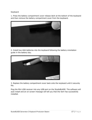
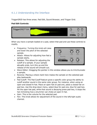
The StudioBLADE (Gen 3) comes with a built-in digital signal processor
(DSP) that handles all audio processing and effects. This frees up the main CPU for
other tasks like sequencing, virtual instruments, and mixing. The DSP provides
ultra-low latency monitoring and playback.
Hear More: The optional StudioBLADE (Gen 3) audio upgrade includes an
additional four (4) balanced 1⁄4‖ line inputs and four (4) balanced 1⁄4‖ line outputs
for a total of six (6) inputs and six (6) outputs. This allows you to connect and
record multiple instruments and microphones simultaneously.
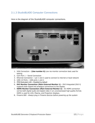
Connectivity: The StudioBL

![StudioBLADE Generation 3 Keyboard Production Station 27 | P a g e
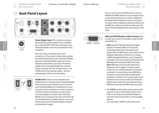
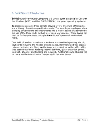
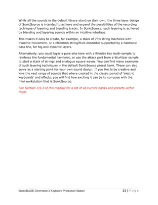
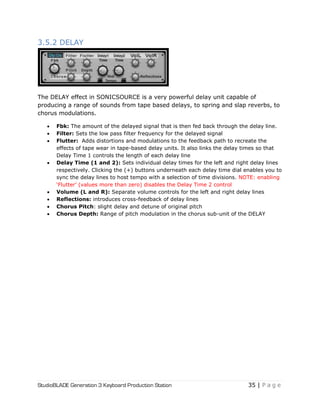
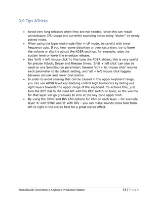
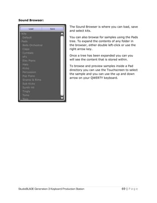
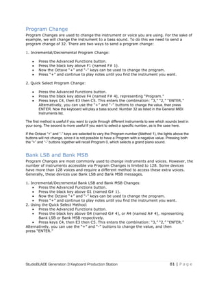
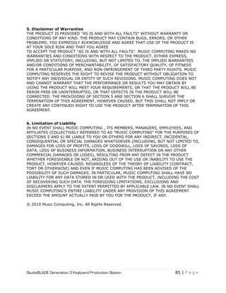
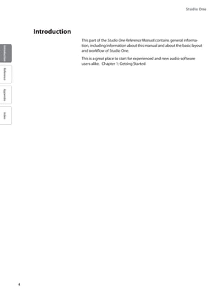
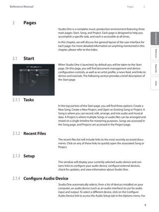
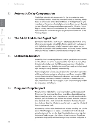
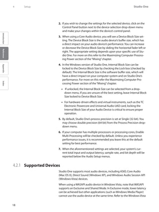
3.1.5 ADSR Envelope
This option sets the Attack, Decay, Sustain and Release for the amplitude of the
layer, as well as for the filter when it is assigned to the envelope. Each envelope
has its own voice-allocation and settings. This is commonly referred to as ―ADSR‖
(ad–zer).
The envelope is not linear- it has logarithmic attack and exponential decay and
release times, thus you may notice extra CPU usage when doing longer attacks,
decays or releases. Also keep in mind that using very long release times will use
more voices. This could cause the sound of some voices to be "stolen" by newer
notes if there are many notes still ‗releasing‘ while you play more notes. If this
happens, and if it is a problem for the song mix, set voices to a higher value [16 is
the highest] or lower the release values on the envelope.
You can use "Shift + Mouse click" to fine tune the ADSR sliders, which can be very
useful for precise Attack, Decay and Release times.
3.1.6 Velocity Sensitivity and Key Scaling
Velocity Sensitivity: The ‗vel sens‘ dial allows you to set velocity sensitivity
independently for each layer. Setting ‗vel sens‘ to the hard left (zero) makes the
envelope insensitive to keyboard velocity pressure – this is useful for such sounds
as B3 and VOX organs, or Mellotron sounds, which as hardware simply feature a
note on/note off keyboard. Moving from the hard left position, the layer becomes
gradually more velocity sensitive for more dynamic playing, suitable for electric
pianos, for instance.
Key Scaling: The KEY dial is for ADSR keyboard tracking. It has two modes [see
icons at right of the + symbol] - ADSR Speed (the higher option) and ADSR Level
(the lower option).
Both modes are active at the same time, and by clicking on the symbols the GUI
toggles between each mode. With ADSR Speed tracking you can scale attack, decay
and release times along the selected key zone for the layer. With ADSR Level
tracking you can scale the envelope amplitude along the selected key zone for the
layer.](https://image.slidesharecdn.com/4cee09e1-25e7-4441-8b08-e26836a7f5f4-160215210245/85/Music-Computing-StudioBLADE-Gen-3-Manual-Full-27-320.jpg)
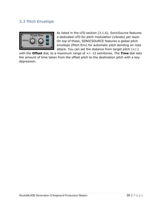
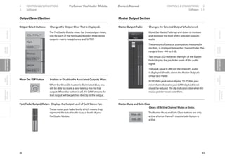
![StudioBLADE Generation 3 Keyboard Production Station 31 | P a g e
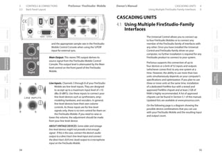
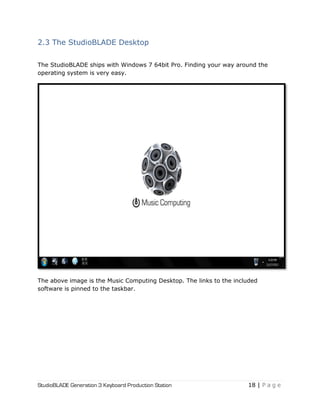
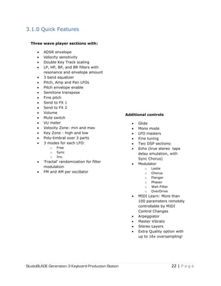
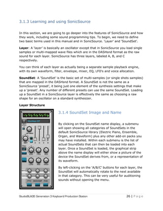
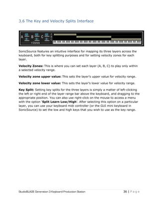
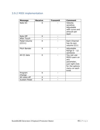
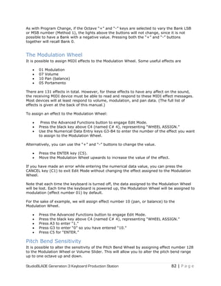
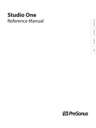
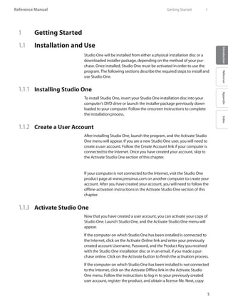
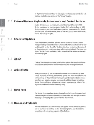
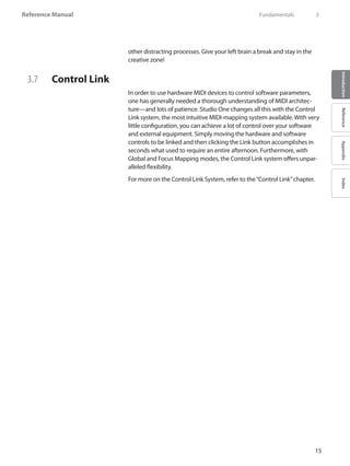
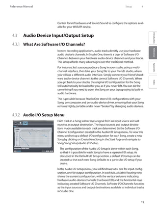
3.4 Master Controls
The section named Master Controls features a number of
global parameters –
PitchBd: Pitch bend adjusts the range for the standard
MIDI Pitch Bend wheel from 1 to 12 semitones.
Voices: Voices is a global control selecting the number
of voices each layer will play. Setting to 16 voices means
that each layer will play 16 voices. For example: Playing
a 16 note chord on each layer would result in a total 48
voices.
Glide: Glide is a portamento effect like you find in many synthesizers. The Glide
dial adjusts the time the pitch takes to shift from one note to the other in two
consecutively pressed keys. Employing this parameter puts SonicSource into MONO
mode (one voice only) as there is no support for polyphonic portamento. The „A‟
button next to Glide toggles between two portamento settings- [On] will glide only
tied notes, while [Off] will glide all consecutive notes.
Fine Tune: The synth can be globally fine tuned with this control.
Vel Sens: adjusts the velocity sensitivity curve of all layers. Turn left for slow
response, and right for fast response to velocity changes.
Digits (LED read out): This "LED" screen shows values for each parameter that
you either hover over with the mouse, or are currently changing. This can be very
helpful for fine tuning a particular sound.
Out Gain: This is a master control for the synth volume.
Limiter: You may use this limiter to avoid excessive level peaks going thru the
synth output. It is a soft-knee limiter, and thus will not totally prevent clipping and
distortion for output that is continuously too loud. If you experience unwanted
output distortion, adjust the layer levels in the SonicSource mixer section, or the
global Out Gain control instead.](https://image.slidesharecdn.com/4cee09e1-25e7-4441-8b08-e26836a7f5f4-160215210245/85/Music-Computing-StudioBLADE-Gen-3-Manual-Full-31-320.jpg)
![StudioBLADE Generation 3 Keyboard Production Station 44 | P a g e
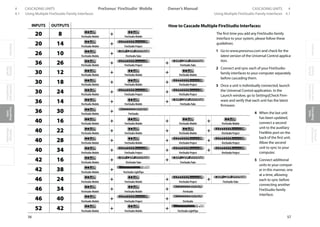
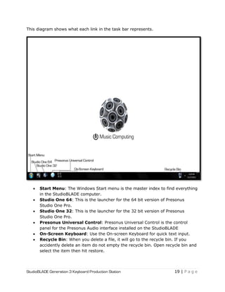
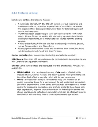
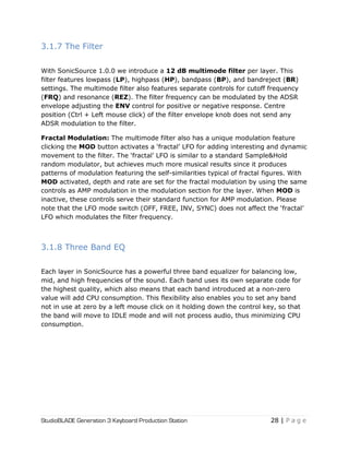
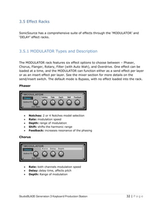
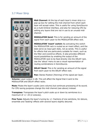
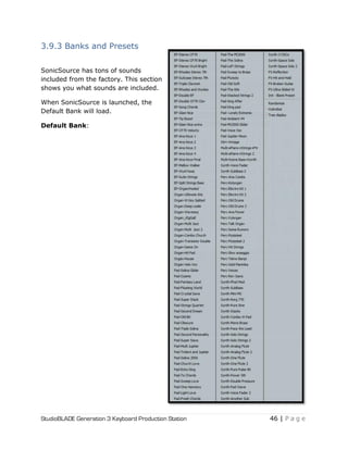
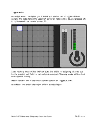
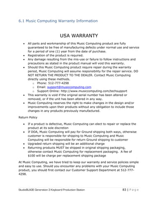
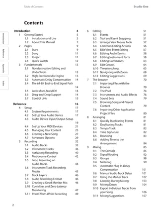
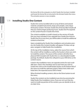
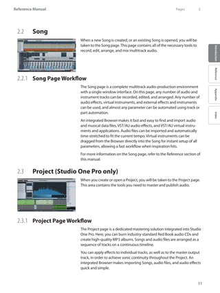
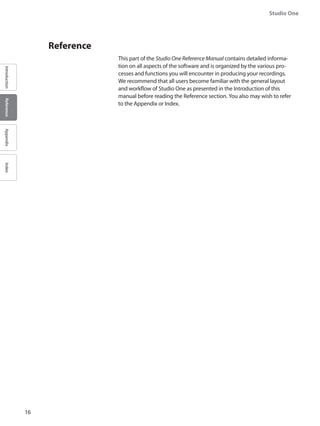
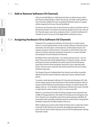
3.9.1 Global Menu and Settings
Global menu and settings are accessed by clicking on the [?] button, or the Music
Computing Logo.
Save default bank: Saves the current bank of presets as the User-Default Bank,
which will load up automatically when you insert a new instance of SonicSource.
Load factory bank: Reloads the internal factory bank.
About: Shows information about the synth authors, version number, and serial
number for this copy of SonicSource. There is also a picture of the SonicSource
routing schemes to help understand the different multi-effect configurations
possible.
Save controller presets: Saves the following parameters as ‗default‘: Volume
(Soft, Normal, High), and AutoGlide.
MIDIForget: Removes all learned Midi-CC information.
Volume: Sets the base volume level between High, Normal and Soft for VST hosts
which have variable volume outputs.
Quality: Oversampling reduces noise by giving you more frequency headroom.
You can oversample in SonicSource up to 16x!](https://image.slidesharecdn.com/4cee09e1-25e7-4441-8b08-e26836a7f5f4-160215210245/85/Music-Computing-StudioBLADE-Gen-3-Manual-Full-44-320.jpg)


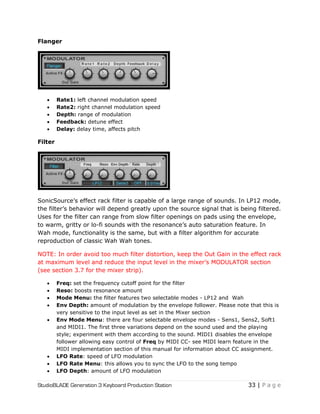
![StudioBLADE Generation 3 Keyboard Production Station 62 | P a g e
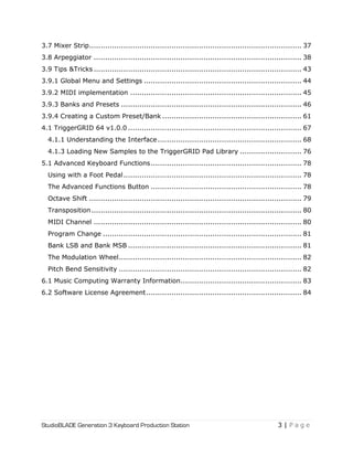
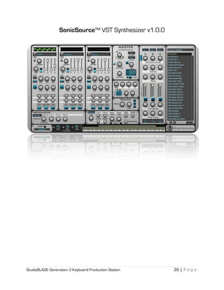
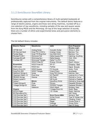
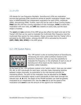
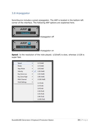
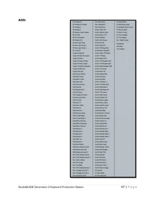
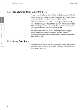
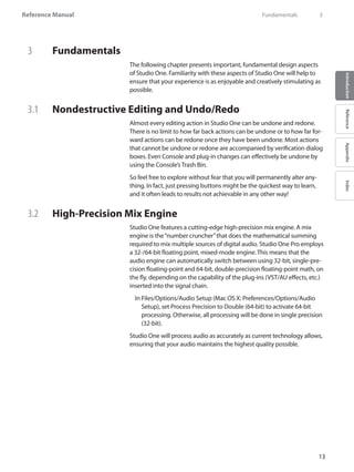
Select Browse Banks>Select the [BLANK] bank.
Once this is done all the presets in the window will be named "Init."](https://image.slidesharecdn.com/4cee09e1-25e7-4441-8b08-e26836a7f5f4-160215210245/85/Music-Computing-StudioBLADE-Gen-3-Manual-Full-62-320.jpg)
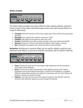
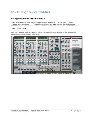
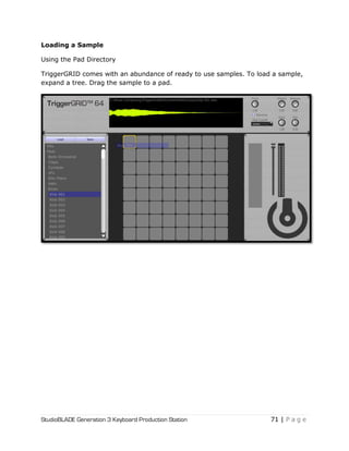
![StudioBLADE Generation 3 Keyboard Production Station 63 | P a g e
Using the blank preset slots....
Select one of the "Init" blank preset slots....
Add sounds into A, B, and/or C. Tweak them how you like.
You will find the raw content for SonicSOURCE in the [WaveForms] folder.
SonicSOURCE will automatically select this folder once you press the [Load Sound]
button.
After you have edited your new sound and ready to go
back to your new list of presets, select [Browse Presets]
this will take you back to the list.](https://image.slidesharecdn.com/4cee09e1-25e7-4441-8b08-e26836a7f5f4-160215210245/85/Music-Computing-StudioBLADE-Gen-3-Manual-Full-63-320.jpg)
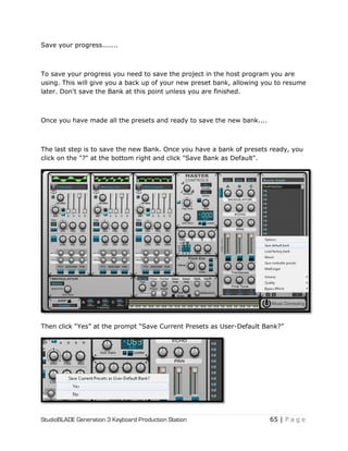
![StudioBLADE Generation 3 Keyboard Production Station 64 | P a g e
Rename the preset to whatever you want by right-clicking the currently selected
blank preset and selecting [Rename].
Either select another "Init" preset in the list and repeat or….
If you want to blend sounds for
simultaneous playback using the
three sound slots of
SonicSOURCE, each engine slot
(A, B, or C) has to be on the
same MIDI channel. You can set
the channel at the top of the
window adjacent to the preset
browser, right above the text that
says A, B, C.).](https://image.slidesharecdn.com/4cee09e1-25e7-4441-8b08-e26836a7f5f4-160215210245/85/Music-Computing-StudioBLADE-Gen-3-Manual-Full-64-320.jpg)
![StudioBLADE Generation 3 Keyboard Production Station 66 | P a g e
That will create a new .bnk file in "C:pluginsMusic ComputingSonicSource
DATASonicSource Banks" directory, the basic name given will be "User Default".
To give that new bank a unique name, you will have to browse to the
aforementioned folder and rename that bank to whatever you want and it's done.
Right-click the file and select [Rename]. That‘s it.](https://image.slidesharecdn.com/4cee09e1-25e7-4441-8b08-e26836a7f5f4-160215210245/85/Music-Computing-StudioBLADE-Gen-3-Manual-Full-66-320.jpg)
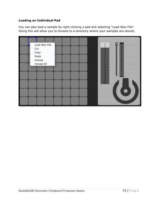
![StudioBLADE Generation 3 Keyboard Production Station 74 | P a g e
Saving a Kit
The [Save] button is for saving the samples you add to the pad grid. A kit can have
up to 64 samples.
Saving will also save all the edits you have made to a sample pad.](https://image.slidesharecdn.com/4cee09e1-25e7-4441-8b08-e26836a7f5f4-160215210245/85/Music-Computing-StudioBLADE-Gen-3-Manual-Full-74-320.jpg)
![Reference Manual
7
IntroductionReferenceAppendixIndex
1.2 About This Manual
1.2.1 Versions
There are currently two versions of Studio One: Studio One Pro and
Studio One Artist. Both run under the Windows and Mac OS X operating
systems. This reference manual will serve both versions; however, Studio
One Artist will not include certain features. A detailed list of these exclu-
sions is provided in Appendix Table 5.
All screenshots provided in this manual are taken from the Windows
(Vista 32-bit) version.
1.2.2 Tips
This manual presents many shortcuts and alternative methods or func-
tions. These tips are intended to improve your workflow, and will be
shown as follows:
Helpful information.
Also note that if you float the mouse over any tool, button, or window in
Studio One for a few seconds, a Tooltip will appear that names the func-
tion the tool, button, or window serves.
1.2.3 Key Commands
Many operations in Studio One have associated key commands, or key-
board shortcuts, that can be used in lieu of navigating menus with the
mouse. Some key commands use modifier keys, and some modifier keys
differ depending on the operating system.
In this manual, key commands with modifier keys are shown with the
Windows modifier key first, as follows: [Win modifier key]/[Mac modifier
key]+[key]. For example: [Ctrl]/[Cmd]-[C] means“press [Ctrl]/[Cmd]+C in
Windows, or press [Cmd]+C in Mac OS X.”
Where there is no difference between the Windows and Mac version of a
key command, only one key command will be displayed. Example: [F3].
In several instances, options are located in the File menu for the Windows
version but in Preferences in the Mac OS X version. In these cases, the
Windows location is given first, and the Mac location follows in [brackets].
A complete list of key commands is provided in Appendix Table 1.
Getting Started 1](https://image.slidesharecdn.com/4cee09e1-25e7-4441-8b08-e26836a7f5f4-160215210245/85/Music-Computing-StudioBLADE-Gen-3-Manual-Full-92-320.jpg)
![Studio One
12
IntroductionReferenceAppendixIndex
2 Page
High-quality master output metering is displayed at all times, including
Spectrum, Peak/RMS, and Phase meters. These tools will help you know at
a glance exactly what is going on in your Project.
As mentioned, Songs can be imported directly into your Projects with-
out having to export a Song mix. After a Song has been imported into a
Project, you can go back and change the Song mix, and the Project will
be automatically updated.
For detailed information on the Project page, refer to the“Mastering”
chapter.
2.4 Quick Switch
In Studio One Pro, you can have multiple Songs and Projects open
simultaneously and can switch between them quickly. The fastest way to
switch between any open Song or Project, as well as the Start page, is to
press [Ctrl]+[Tab] and continue to hold [Ctrl] on the keyboard. This will
display a pop-up list of all open documents.
While holding [Ctrl], press [Tab] to cycle through the open documents.
Release [Ctrl] when the desired document is selected; now you can view
that document.](https://image.slidesharecdn.com/4cee09e1-25e7-4441-8b08-e26836a7f5f4-160215210245/85/Music-Computing-StudioBLADE-Gen-3-Manual-Full-97-320.jpg)
![26
Studio One
IntroductionReferenceAppendixIndex
4 Setup
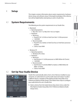
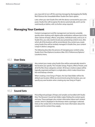
4.5.3 Instrument Library
Studio One includes a native virtual instrument called Presence that
utilizes built-in sounds and SoundFonts. SoundFonts contain one or more
audio samples that can be resynthesized at different pitches and dynamic
levels. Using the Instrument Library, Presence can browse for sounds,
which are seen as presets.
To add SoundFont files to your Instrument Library, in the File/Options/Lo-
cations/Instrument Library [Mac OS X: Preferences/Locations/Instrument
Library] menu, click on the Add button and specify a file location, then
click OK.You can specify as many locations as you need.
For more information on the Presence built-in virtual instrument, refer to
the Presence section of the“Built-In Virtual Instruments”chapter.
4.5.4 Locating Plug-ins
When Studio One is started for the first time, most of your plug-ins are
located automatically and are ready to use immediately. If you find that
certain plug-ins are not found, adding them is easy.
To add any missing VST plug-ins to Studio One, navigate to the
Files/Options/Locations/VST Plug-ins (Mac OS X: Preferences/Options/
Locations/VST Plug-ins) menu and click on the Add button, then specify
a location and click OK.You can also drag-and-drop any folder from the
Explorer/Finder into the Locations list. Studio One Pro will then scan these
locations at startup, including searching for new plug-ins you’ve added.
You can always add more locations if needed.
AU, VST3, and ReWire-enabled plug-ins and applications have their own
file path in the OS and will not have to be located manually.
4.5.5 Failed Plug-ins
If any plug-in fails to start correctly when scanned at startup, a
notice will appear next to its name in the startup message list, and
a warning message should appear. If the plug-in continues to fail at
startup—for instance, if it is not authorized correctly or a required
iLok key is not present—Studio One Pro will put the plug-in in a
blacklist and ignore it at startup from that point on.
To reset this blacklist and force Studio One Pro to scan missing plug-ins
again at startup, navigate to Files/Options/Locations/VST Plug-ins (Mac
OS X: Preferences/Options/Locations/VST Plug-ins) and click on Reset
Blacklist. The next time you start Studio One Pro, the previously blacklist-
ed plug-ins will be scanned again. If the issues that caused the plug-ins to
fail the scan have been resolved, the plug-ins will be made available.](https://image.slidesharecdn.com/4cee09e1-25e7-4441-8b08-e26836a7f5f4-160215210245/85/Music-Computing-StudioBLADE-Gen-3-Manual-Full-111-320.jpg)
![27
Reference Manual
IntroductionReferenceAppendixIndex
4.5.6 VST Support
Studio One Pro supports VST 2.4 (including VSTXML for hierarchical
parameter structure) and VST 3. As VST 3 is a new technology, and Studio
One Pro is one of the few non-Steinberg host applications that support it,
there may be incompatibility problems with some plug-ins. These prob-
lems will need to be resolved over time.
4.6 Creating a New Song
A Song is where all recording, editing, arranging, and mixing takes place.
To create a New Song, do one of the following:
From the•• Start page, click on the New Song link.
Navigate to File/New•• Song.
Press [Ctrl]/[Cmd]+N on the keyboard.••
From the•• Project page, if no Song is currently open, click on the Song
quick-access button.
4.6.1 Song Templates
On the left side of the New Song creation menu (see Fig. 4-12), you will
find a list of preconfigured Song templates, which are designed to help
get you started quickly with various recording tasks. The templates can
include particular I/O and track setups, effects plug-in and virtual-instru-
ment processing, and all other aspects of a Song. By default, the Empty
Song template is selected, which will create a completely empty Song
with no tracks or preconfigured I/O setup.
4.6.2 Create a Song Template
If there is a particular Song setup you will be using again and again, it can
be helpful to create a template. To do so, first create a new Empty Song.
Next, configure the I/O and create and configure all tracks, and virtual
instruments, effects plug-ins, and any other aspects of the Song that you
need in your template. Then, in the File menu, select Save as Template.
Type in a title and description, choose an image for the Template icon,
if you like, and select OK.You can also drag an image from Windows
Explorer/Mac Finder onto the image icon to use that image. The exact
current state of the Song will now be available as a template in the New
Song creation menu.
Setup 4](https://image.slidesharecdn.com/4cee09e1-25e7-4441-8b08-e26836a7f5f4-160215210245/85/Music-Computing-StudioBLADE-Gen-3-Manual-Full-112-320.jpg)
![32
Studio One
IntroductionReferenceAppendixIndex
5 Recording
5 Recording
The following chapter discusses aspects of recording in Studio One, in-
cluding Audio and Instrument Tracks, recording modes and formats, and
recording tips.
5.1 Audio Tracks
Before recording can take place, you need at least one track on which to
record. Studio One has two types of tracks for basic recording: the Audio
Track and the Instrument Track. Audio is recorded to Audio Tracks, while
musical-performance data is recorded to Instrument Tracks.
5.1.1 Creating an Audio Track
To create an Audio Track, navigate to Track/Add Tracks or Press [Ctrl]/
[Cmd]+T to open the Add Tracks menu. The following options are avail-
able in this menu:
Name: Click here and type in a name for the new track••
Count: Choose the number of tracks you would like to create••
Format: Choose a mono or stereo•• Audio Track
Preset: Choose an•• FX Chain to be preloaded on the tracks
Color: Choose a color••
Auto-Color: Check this box if you would like your tracks auto-colored••
Once these options are configured, click on OK, and the tracks will appear
in the Arrange view.
Navigate to Track/Add Audio Track to quickly add a mono audio track.
[Right]/[Control]-click in blank space in the Track Column and select Add
Tracks For All Inputs to quickly add a track for every configured input in
Audio I/O Setup.
Alternatively, you can right click in any blank space in the Track Column of
the Arrange view and select Add Audio Track (Mono) or Add Audio Track
(Stereo) to quickly add an audio track.
5.1.2 Use and Create Presets
In Studio One, you can store presets of an entire chain of effects plug-ins
as an FX Chain, allowing quick recall of complex effects setups on any
track. Any factory-preset or user-created FX Chain can be selected as a
Preset when creating a track. For more information, refer to the FX Chain
section of the“Mixing”chapter.](https://image.slidesharecdn.com/4cee09e1-25e7-4441-8b08-e26836a7f5f4-160215210245/85/Music-Computing-StudioBLADE-Gen-3-Manual-Full-117-320.jpg)
![33
Reference Manual
IntroductionReferenceAppendixIndex
5.1.3 Configuring an Audio Track
This section describes the editable Audio Track parameters.
5.1.4 Input/Output Selection
An Audio Track’s I/O channel(s) can be selected from three places: the
Track Column, the Console, and the Track Inspector.
Selecting an Input Channel from the Track Column:
Set the•• Arrange view Track size to medium or larger to be able to access
the current Input Channel selection for any track.
Click in the window immediately below the horizontal track fader to••
choose from any configured Input Channel.
Selecting an Input or Output Channel from the Console:
Open the•• Console by clicking the Mix button, or press [F3] on the key-
board, and be sure either All Channels or Audio is selected in the Banks
window.
Click in the window above each track’s•• Fader and Pan controls to
choose an Input and/or Output Channel. The Input Channel selector is
on top, with the Output Channel selector beneath.
Selecting an Input or Output Channel from the Inspector:
Open the•• Inspector window by clicking on the Inspector button above
the Track Column or pressing [F4] on the keyboard.
At the top of the•• Inspector window, you will find the currently selected
track’s Channel Mode toggle (mono or stereo) and Input and Output
Channel selectors)
Click on the Input or•• Output Channel selector to choose a channel.
The available Input Channels for an Audio Track will be based on the
track’s channel mode (mono or stereo), which can be toggled with the
Channel Mode button.
Recording 5](https://image.slidesharecdn.com/4cee09e1-25e7-4441-8b08-e26836a7f5f4-160215210245/85/Music-Computing-StudioBLADE-Gen-3-Manual-Full-118-320.jpg)
![34
Studio One
IntroductionReferenceAppendixIndex
5 Recording
5.1.5 Tempo Mode
The Tempo Mode, found in the Inspector, affects the way in which Audio
Events are handled on any audio track. There are three Tempo Modes:
Don’t Follow:•• Audio Events on the selected track will not be affected by
Song tempo.
Follow: The start position of•• Audio Events on the selected track will be
adjusted with tempo changes, so the events stay in sync with their Bars
(bars and beats) position. The length of the Event will not be affected.
Timestretch: Assuming that the•• Song file contains tempo information,
tempo changes will cause Audio Events on the selected track to be
dynamically stretched so that the events’start and end times stay in
sync with their Bars (bars and beats) positions. The length and internal
timing of the Event will be affected in the stretching process; however
the pitch of the audio will remain unaffected.
If the Stretch Audio Loops to Tempo option is selected when creating a
new Song, Timestretch will be the default tempo mode for all new Audio
Tracks.
5.1.6 Record-Enabling an Audio Track
To record to an Audio Track, the track must be record-enabled (see Fig.
5-6). To record-enable an Audio Track, click on the track’s Record Enable
button once or select the track and press [R] on the keyboard. Select mul-
tiple tracks and record-enable any of them to record-enable all selected
tracks. The Record Enable button will turn red when active, and the track’s
meter will begin to move up and down if there is live audio input on the
track’s selected Input Channel.
Alternatively, if you press and hold [Alt]/[Option] on the keyboard, and
then click on Record Enable, you will both record-enable the related track
and disarm record-enable for all other tracks.
In the Track menu, you will find the Record+Monitor Follows Selection
option. Engaging this automatically record- and monitor-enables the last
track selected in the Arrange view.
When an Audio Track is record-enabled, a clip indicator will appear at the
top of the input-level meter for that track in the Arrange view. If clipping
occurs at the input, the clip indicator will turn on. When clipping occurs,
you should adjust the input gain/level on your audio interface, as once
the distorted signal is recorded, it cannot be fixed.
Once an Audio Track is record-enabled, you are ready to record. Refer to
Activating Recording for more on this topic.](https://image.slidesharecdn.com/4cee09e1-25e7-4441-8b08-e26836a7f5f4-160215210245/85/Music-Computing-StudioBLADE-Gen-3-Manual-Full-119-320.jpg)
![35
Reference Manual
IntroductionReferenceAppendixIndex
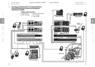
5.1.7 Software Monitoring
To monitor (listen to) live audio input on an Audio Track in Studio One,
click on the Monitor enable button once. This button should turn blue,
and you should begin to hear your live audio input and see its input level
on the track meter.You can also hold [Alt]/[Option] on the keyboard and
then click on the Monitor enable button to simultaneously engage moni-
toring on a track and disengage monitoring on all other tracks.
It may be helpful to picture the signal path to understand exactly what is
happening. For example, if the audio source you are listening to is a guitar
plugged into channel 1 on your audio interface, then Studio One receives
the guitar input on Hardware Input 1.
In Audio I/O Setup, you will have created a mono Input Channel with
Hardware Input 1 as its source.Your Audio Track will have that Input
Channel selected as its input. The output of your Audio Track is likely to
be the Main Output, which is a stereo Output Channel. That Output Chan-
nel will output to a designated stereo pair of outputs on your hardware
audio interface, which normally would be connected to your monitor
speakers or headphones.
When monitoring live audio input from a microphone, avoid listening
with speakers that are in close proximity to the microphone. It is possible
in this case to create a feedback loop that can quickly generate danger-
ously loud audio levels, possibly harming your ears and your speakers.
5.1.8 Hardware Monitoring
Some audio interfaces feature the ability to monitor the hardware inputs
and outputs directly, as opposed to monitoring through software. This is
referred to as“hardware monitoring”or“zero-latency monitoring.”When
using this type of interface, it is recommended that you monitor live
audio input via hardware monitoring instead of software monitoring. This
will help you avoid common problems that result from software latency,
such as hearing a delay on your voice while you record vocals, or record-
ing off-beat.
5.1.9 Setting Input Levels
Setting good input levels is critical to making a good recording. This
begins with the hardware audio interface. If the hardware’s input level is
set too low, and you increase the level later in Studio One to compensate,
you will also raise the level of any noise in the signal. If the level is too
high, you can overload the hardware input, causing unpleasant clipping
distortion that cannot be fixed. Therefore, you should set the input gain
on your audio interface as high as possible without overloading the in-
put. There is usually a clip indicator for each input on the audio interface
to assist you in detecting overloads.
Recording 5](https://image.slidesharecdn.com/4cee09e1-25e7-4441-8b08-e26836a7f5f4-160215210245/85/Music-Computing-StudioBLADE-Gen-3-Manual-Full-120-320.jpg)
![36
Studio One
IntroductionReferenceAppendixIndex
5 Recording
As long as the input levels are not clipping in your audio interface or on
the track to which you are recording in Studio One, you can always adjust
the levels of recorded material after the recording is made. To visually
monitor the input levels for any input in Studio One, it is best to view the
Input Channels in the Mix Console by selecting the Inputs bank in the
Banks window.
5.2 Instrument Tracks
Instrument Tracks are where performance data is recorded, drawn, and
edited. This data usually comes from a Keyboard, which is used to play a
virtual instrument. The performance data is not audio; the virtual instru-
ment being played by the Keyboard is the audio source.
In Studio One, MIDI controllers are referred to as Keyboards. If you have
not set up a Keyboard, refer to the Set UpYour MIDI Devices section of
the“Setup”chapter.
5.2.1 Creating an Instrument Track
To create an Instrument Track, navigate to Track/Add Tracks or Press [Ctrl]/
[Cmd]+T to open the Add Tracks menu. The following options are avail-
able in this menu:
Name: Click here and type in a name for the new track.••
Count: Choose the number of tracks you would like to create.••
Format: Choose Instrument Track.••
Color: Choose a color.••
Auto-Color: Check this box if you would like your tracks auto-colored.••
Once these options are configured, click on OK, and the tracks will appear
in the Arrange view. It is important to note that Instrument Tracks do not
appear directly in the Console, as they do not output audio. The virtual in-
struments generate sound and are represented in the Console by Instru-
ment Channels.
Alternatively, [Right]/[Control]-click in a blank space in the Track Column
of the Arrange view and select Add Instrument Track from the pop-up
menu to quickly add an Instrument Track.
5.2.2 Configuring an Instrument Track
In Studio One, an Instrument Track can only receive input from a Key-
board that has been set up in the External Devices menu. To set up a
Keyboard, refer to the Set UpYour MIDI Devices section of the“Setup”
chapter. If you have a Keyboard set up as the default Instrument Track
input, all Instrument Tracks will default to using that Keyboard.](https://image.slidesharecdn.com/4cee09e1-25e7-4441-8b08-e26836a7f5f4-160215210245/85/Music-Computing-StudioBLADE-Gen-3-Manual-Full-121-320.jpg)
![37
Reference Manual
IntroductionReferenceAppendixIndex
An Instrument Track can trigger a virtual instrument that has been set
up in a Song or an External Instrument. The Instrument Track Input and
Output can each be selected in one of two places:
Selecting an Instrument Track Input or Output from the Track Column:
Set the Arrange view Tracksize to medium or larger to be able to access••
the current Instrument Track Input.
There are two selection windows on the Instrument Track. Click in the••
bottom window to choose from any configured Keyboard input. Click
in the Top window to choose an output to any previously set up virtual
or external instrument.
Selecting an Instrument Track Input or Output from the Inspector:
Open the•• Inspector window by clicking on the Inspector button above
the Track Column or by pressing [F4] on the keyboard.
Click in the Input or Output selector window to select from any con-••
figured Keyboard input or to trigger any previously set up virtual or
external instrument.
Press [F11] to open the instrument editor for the selected Instrument
Track.
5.2.3 Set Up a Virtual Instrument
Studio One Pro supports VST and AU virtual instruments, ReWire appli-
cations, and Studio One Pro’s Native virtual instruments. The difference
between these types of virtual instruments is transparent to the user in
Studio One Pro, as they are all handled in the same manner. To use any
VST or AU virtual instrument, you will need to be sure Studio One knows
where they are installed on your computer. Refer to the Locating Plug-
ins section of the“Setup”chapter for more information on locating your
plug-ins.
5.2.4 Add a Virtual Instrument from the Browser
To add any VST, AU, ReWire, or built-in virtual instrument to your Song:
Open the Browse view and click on the•• Instruments tab to view your
virtual instrument.
Do one of the following:••
Click on and drag any virtual instrument to an empty space in the••
Arrange view to simultaneously add the virtual instrument to your
Song and create an Instrument Track with its output routed to the
virtual instrument. The Instrument Track will conveniently inherit the
name of the virtual instrument.
Recording 5](https://image.slidesharecdn.com/4cee09e1-25e7-4441-8b08-e26836a7f5f4-160215210245/85/Music-Computing-StudioBLADE-Gen-3-Manual-Full-122-320.jpg)
![38
Studio One
IntroductionReferenceAppendixIndex
5 Recording
Click on and drag any virtual instrument on top of an existing Instru-••
ment Track to replace the track’s current virtual instrument.
Click on and drag any virtual instrument to the•• Instruments window
in the Mixer to simply add the virtual instrument to your Song. In or-
der to control or play this virtual instrument, you will need to select it
as the output for an Instrument Track.
The virtual instrument is now set up and ready to play and will have••
one or more dedicated audio channels in the Mixer.
Once a virtual instrument is added to your Song, be sure that an Instru-
ment Track is routed to it so that the instrument can be played.
5.2.5 Set Up Multiple Virtual Instrument Outputs
Many virtual instruments have the capability to send audio on more than
one channel. In Studio One, only the first output or output pair of any
virtual instrument will be active by default. To activate the other possible
virtual-instrument output channels in the Console:
Open the•• Console by pressing [F3] on the keyboard, then open the
Instruments panel (open by default) by clicking on the Instr. button to
the far left of the Console.
Click once on the virtual instrument in the•• Instruments panel, and the
output-channel activation menu will expand.
Click on the checkbox next to any output to activate that output for the••
virtual instrument.
Each active virtual-instrument output will have a dedicated audio chan-••
nel in the Console.
You can also activate virtual-instrument outputs in the plug-in window.
Any virtual-instrument plug-in that offers multiple output channels will
have a Channels button at the top of the plug-in window. Click on this
button to view and activate the available outputs.
5.2.6 Set Up a ReWire™ Application
ReWire applications are set up in a similar way to virtual instruments. Any
ReWire applications known to Studio One Pro will be listed in the Browser
Instruments tab, along with all known virtual instruments.You can drag in
the ReWire application just like an instrument, and Studio One Pro has a
special ReWire object to represent the application.
The ReWire interface window is similar to the virtual-instrument interface
windows.There are also two special controls, Open Application and Close
Application, which can open and close most ReWire applications, so you do
not need to leave Studio One Pro to open or close the ReWire application .](https://image.slidesharecdn.com/4cee09e1-25e7-4441-8b08-e26836a7f5f4-160215210245/85/Music-Computing-StudioBLADE-Gen-3-Manual-Full-123-320.jpg)
![40
Studio One
IntroductionReferenceAppendixIndex
5 Recording
5.2.10 Monitoring an External Instrument
To monitor and ultimately record the hardware audio output of an
external instrument, one or more Audio Tracks need to be created to
receive that output. This means that your external instrument needs to be
physically connected to one or more inputs on your audio interface. Thus,
monitoring an external instrument involves the following:
The output of an Instrument Track is routed to the external instrument,••
which has been set up to receive MIDI input from Studio One.
The Instrument Track is monitor-enabled.••
One or more•• Audio Tracks have been created and configured to use
the Input Channels to which the external instrument’s audio output is
connected.
The•• Audio Tracks are monitor-enabled.
With the above conditions met, you will be able to play your Keyboard
and see the Instrument Track meter moving.You will also see the related
Audio Track meters moving, as well as hear the live audio input from the
external instrument.
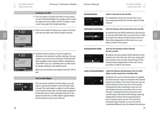
5.3 Activating Recording
Once you have the desired tracks created, setup, and record-enabled, the
next step is to record. The following illustrates several ways to activate
recording, each associated with a different purpose.
5.3.1 Manually
Manually activating recording is the most basic way to record. Recording
will start at the current Playback Cursor position and will continue until
you manually stop recording. To manually activate recording, click on the
Record button in the Transport or press [NumPad *] on the keyboard. The
Record button in the Transport will turn red, the Playback Cursor will start
to scroll from left to right, and a new Event will be recorded to any record-
enabled tracks. Recording will continue until you manually stop it.
5.3.2 Pre-Roll
Recording with Pre-Roll engaged allows you to specify a number of bars
that will play before recording begins. For instance, when you want to
record a vocal part for a chorus, the vocalist will need to hear some refer-
ence portion of the recorded tracks before beginning to sing. A guitarist
recording a solo will need to hear the music leading into the solo. Pre-Roll
allows you to specify the number of bars you will hear before record-
ing automatically starts and saves you the trouble of deleting the space
before the recorded part actually begins.](https://image.slidesharecdn.com/4cee09e1-25e7-4441-8b08-e26836a7f5f4-160215210245/85/Music-Computing-StudioBLADE-Gen-3-Manual-Full-125-320.jpg)
![41
Reference Manual
IntroductionReferenceAppendixIndex
Follow these steps to use Pre-Roll:
Click on the•• Pre-Roll button in the Transport or press [O] on the key-
board to engage Pre-Roll.
Click on the•• Metronome Setup button to open the Metronome Setup
menu.
Under•• Precount in the Metronome Setup menu, enter a number in
the Precount Bars field for the number of bars you wish to play before
recording begins.
Set the•• Playback Cursor to the timeline position at which you wish to
begin recording.
Click on the Record button in the•• Transport or press [NumPad *] to
begin recording. Playback will begin at the specified number of bars
before the position you chose, with the Playback Cursor moving from
left to right.
•• Recording will automatically activate at the position you chose. The
Record button in the Transport will turn red, the Playback Cursor will
continue to scroll from left to right, and a new Event will begin record-
ing to any record-enabled tracks.
•• Recording will continue until you manually stop it by pressing [Space
Bar] on the keyboard or clicking Stop in the Transport.
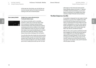
5.3.3 Auto Punch
It is sometimes useful to automate the point at which recording will
begin and end. For example, if you wish to record over a specific phrase
of a vocal part, but not before or after that phrase, you can automatically
begin and end recording at specified points. This process is commonly
referred to as“punching in and out,”and the resulting new Audio Event is
referred to as the“punch-in.”
In Studio One, punching in/out is achieved with the Auto Punch feature.
Follow these steps to engage Auto Punch:
Set the Left Locator in the•• Timeline Ruler of the Arrange view at the
position you wish to punch in—that is, where recording should begin.
Set the Right Locator in the•• Timeline Ruler of the Arrange view at the
position you wish to punch out, that is, where recording should stop.
Click on the Auto•• Punch button in the Transport, or press [I] (the letter
‘i’) on the keyboard.
With tracks record-enabled, begin playback at any point before the Left••
Locator position.
•• Recording will automatically activate at the Left Locator position. The
Record button in the Transport will turn red, the Playback Cursor will
Recording 5](https://image.slidesharecdn.com/4cee09e1-25e7-4441-8b08-e26836a7f5f4-160215210245/85/Music-Computing-StudioBLADE-Gen-3-Manual-Full-126-320.jpg)
![42
Studio One
IntroductionReferenceAppendixIndex
5 Recording
continue to scroll from left to right, and a new Event will begin record-
ing to any record-enabled tracks.
•• Recording will automatically stop at the Right Locator position. Howev-
er, playback will continue beyond the Right Locator position until you
manually stop it by pressing [Space Bar] on the keyboard or by clicking
Stop in the Transport.
If you use the Auto-Punch feature in Studio One to record your punch-ins,
or if you punch in manually, the newly recorded audio is automatically
crossfaded at its edges with the existing Audio Event, so the transition
between the old and new audio is not audible. The crossfade time will be
very small and not audible; however, you can edit the crossfade manually.
5.4 Metronome Control
A metronome makes audible clicks or other sounds that correspond to
beats at a selectable tempo, providing the musicians with a tempo refer-
ence while recording. This is especially useful when recording drums or
other rhythm-intensive tracks, as the editing and arranging processes are
made much easier when the recorded audio lines up with musical bars
and beats.
In Studio One, the metronome can be engaged and disengaged both
globally and for each hardware output in the Console, including the Main
Out and any Sub Outs.
5.4.1 Turn the Metronome On/Off Manually
In the Transport, the Metronome button is to the left of the Master
Volume fader and meter. Click on the Metronome button, or press [C] on
the keyboard, to globally engage and disengage the metronome. The
metronome is globally disengaged by default.
The Output Channels in the Console also feature Metronome buttons and
level controls to the right of the Mute and Solo buttons. These controls
allow you to choose, for each output, whether or not the metronome will
be heard and its level.](https://image.slidesharecdn.com/4cee09e1-25e7-4441-8b08-e26836a7f5f4-160215210245/85/Music-Computing-StudioBLADE-Gen-3-Manual-Full-127-320.jpg)
![44
Studio One
IntroductionReferenceAppendixIndex
5 Recording
folder. Any audio file added to the Clicks folder will become available as
a choice for the Downbeat and Accent Level sample in the Metronome
Settings menu.
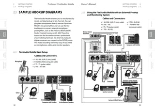
5.5 Loop Recording on Audio Tracks
It can be very useful to loop a specific section while recording in order to
capture multiple performances or takes of the same musical passage. In
Studio One, this is called“Loop Recording.”
Follow these steps to accomplish Loop Recording:
Set the•• Left and Right Locators in the Timeline Ruler at the beginning
and end, respectively, of the area in which you wish to record.
Click on the•• Loop button in the transport or press [NumPad /] on the
keyboard to engage Looping.
Activate•• recording manually or via Pre-Roll or Auto Punch.
When the•• Playback Cursor reaches the Right Locator position, it will
loop back to the Left Locator Position.
•• Recording will continue until you manually stop it by pressing [Space
Bar] on the keyboard or clicking Stop in the Transport.
When Loop Recording with Audio Tracks, multiple Takes will be created.
These Takes represent each recorded pass over the looped region, and
they are contained in a single Audio Event. Only one Take is accessible at
any given time in the Arrange view, and only the currently selected take
will be seen and heard.
5.5.1 Selecting Takes of an Audio Event
When there are multiple Takes available for an Audio Event, the Take icon
will appear in the lower left corner of the Event in the Arrange View.
By default, the last recorded Take is selected. To select any other take,
[Right]/[Control]-click on the Audio Event to expose a list of Takes. Click
on any numbered Take to select it. Takes are edited as a single Audio
Event, so sizing or splicing any Take will splice all of the Takes contained in
the Audio Event.
It is possible to splice an Audio Event that contains multiple Takes, then
select a different Take for each splice of the original Event. As an example,
if you recorded three Takes for a vocal verse, you could split that Audio
Event in between each vocal phrase, and then for each phrase select the
best Take from any of the three Takes.](https://image.slidesharecdn.com/4cee09e1-25e7-4441-8b08-e26836a7f5f4-160215210245/85/Music-Computing-StudioBLADE-Gen-3-Manual-Full-129-320.jpg)
![45
Reference Manual
IntroductionReferenceAppendixIndex
5.5.2 Unpack Takes to New Tracks
When two or more Takes exist for an Audio Event, it is possible to unpack
the individual takes to separate Events on new Tracks. To do this, [Right]/
[Control]-click on the Event and select Unpack Takes to New Tracks. Each
Take will be placed at the appropriate time on its own new Track. Note
that the settings of the originating Track are not duplicated for the new
Tracks.
5.6 Instrument Track Recording Modes
When recording to an Instrument Track, there are several recording
modes. To switch between these modes, navigate to the Transport file
menu and select Record Mode Overdub or Record Mode Replace, and
Loop Record Takes or Loop Record Mix. The following describes each
Instrument Track recording mode.
5.6.1 Record Mode Overdub and Replace
When in the Overdub recording mode, recording over any existing Instru-
ment Part will result in the newly recorded material being overdubbed, or
added to, the existing material. While recording, you will hear the previ-
ously recorded Event playing, as well as hearing the material currently
being recorded, assuming that you are monitoring the Instrument Track.
When in the Replace recording mode, recording over any existing Instru-
ment Part will result in the new material being recorded to a new Event,
which replaces that portion of the original Event. While recording, you
will not hear the previously recorded Event playing back, as the purpose
of this mode is to replace the existing material.
5.6.2 Loop Record Takes and Mix
If Loop is engaged in the Transport while recording, the recording mode
will change to Loop Record Takes or Loop Record Mix. These modes are
functionally similar to the regular Record Mode Overdub and Record
Mode Replace.
When Loop Record Takes is selected, each pass through the looped
region is recorded to a new Take within a single new Instrument Part.
When recording is stopped, eachTake is individually selectable by [Right]/
[Control]-clicking on the Instrument Part and choosing one of the num-
bered takes from the top of the pop-up menu. Only one Take can be
selected at a time for any Instrument Part.
Takes on Instrument Parts can be unpacked to new Instrument Takes, as
with Audio Event Takes, described in the Unpack Takes to New Tracks sec-
tion of this chapter.
Recording 5](https://image.slidesharecdn.com/4cee09e1-25e7-4441-8b08-e26836a7f5f4-160215210245/85/Music-Computing-StudioBLADE-Gen-3-Manual-Full-130-320.jpg)
![46
Studio One
IntroductionReferenceAppendixIndex
5 Recording
When Loop Record Mix is selected, each pass through the looped region
is added to the existing material within a single new Instrument Part. For
instance, if you are looping a four-bar region to record a new drum part,
this would allow you to play one piece of the drum kit during each pass
until you have recorded the whole part.
5.7 Track Layers
In Studio One, both audio and instrument tracks have optional layers
that can be used to record multiple different ideas to a single track. For
instance, you might want to compare one set of lyrics for a vocal track
to another set of lyrics. In this case, you could record two different per-
formances on a single track to two separate layers, and then be able to
quickly switch between the two without the need for a second track.
To create a new layer on any track, open the Inspector by pressing [F4]
on the keyboard and select“Add Layer”from the Layer selection box. The
new layer is effectively like having a whole new track, without the need
for duplicating inserts, sends, and I/O setup.You can also duplicate layers
by selecting Duplicate Layer from the Layer selection box, which enables
you to try out and compare two completely different edits of the same
events on two layers.
5.8 Audio Recording Format
Studio One records in the Broadcast Wave file format. This is the only for-
mat supported, as it is the most widely used format, and it contains time
stamps for when recordings start within a Song.
When recorded Broadcast Wave audio files get bigger than 4 GB, the RF64
file format is automatically used as the standard file format.
The recommended file system for the recording partition on your com-
puter is NTFS on Windows and HFS+ on Mac OS X.
5.9 Creating a Good Monitor Mix
When recording any performance in the studio, it is highly recommended
that you take the time to build a great monitor mix for the performers.
It’s critical that they clearly hear their performance and that of the other
musicians, and a good monitor mix helps inspire a better performance.
The general philosophy is for each performer to feel like they are playing
on a finished record.
For instance, it is common in many styles of music for the lead vocals to
have some reverb so that they sit well in the space of the overall mix.
Therefore, when recording vocals, it is sometimes a good idea to include
reverb in the vocalist’s monitor mix. This way, the vocal will sound more
like a finished production. This approach often helps when recording](https://image.slidesharecdn.com/4cee09e1-25e7-4441-8b08-e26836a7f5f4-160215210245/85/Music-Computing-StudioBLADE-Gen-3-Manual-Full-131-320.jpg)
![52
Studio One
IntroductionReferenceAppendixIndex
6 Editing
6.3 Arrange View Mouse Tools
The mouse tools allow direct interaction with Events, using the mouse. It
is helpful to remember that actions done using the Mouse Tools can be
undone at any time, so feel free to explore them. Click the middle mouse
button (scroll wheel) to display a list of the tools; then left-click to select
the desired tool.
In the Arrange view, the following
Mouse Tools and related functions
are available.
6.3.1 Arrow Tool
This tool is selected by default. Click on the Arrow Tool button or press
[number 1] (above the regular QWERTY keys) on the keyboard to select
the Arrow Tool.
Holding [Ctrl]/[Cmd] on the keyboard while the Arrow Tool is selected will
temporarily switch to the Range Tool.
The Arrow Tool can be used for the following purposes:
6.3.1.1 Move an Event
To move an Event using the Arrow Tool, click anywhere on the Event and
drag left, right, up, or down. Dragging the Event left or right will move the
Event backward and forward in time, relative to the current Timebase and
Timeline zoom. Dragging the Event up or down will move the Event to
another existing track of the same type. If the Event is dragged to a posi-
tion where no track currently exists, Studio One will create a new track of
the same type.
6.3.1.2 Size an Event
Events can be thought of as windows into audio files and musical perfor-
mances, where what you see is what you will hear. Sizing is a fundamental
technique wherein Events are made shorter or longer, so that only a por-
tion of the audio or musical data they contain is seen and heard.
To size any Event using the Arrow Tool, float the mouse to the left or right
edge of the Event to reveal the Sizing Tool. When this tool appears, click-
and-drag left or right to size the Event. Events can be sized and resized
nondestructively any number of times.
Holding [Alt]/[Option] on the keyboard and then sizing an Event from
the right edge will result in the Event being Timestretched. Refer to the
Timestretching section of this chapter for more information.](https://image.slidesharecdn.com/4cee09e1-25e7-4441-8b08-e26836a7f5f4-160215210245/85/Music-Computing-StudioBLADE-Gen-3-Manual-Full-137-320.jpg)
![53
Reference Manual
IntroductionReferenceAppendixIndex
6.3.1.3 Adjust Audio Event Volume Envelopes
All Audio Events feature a basic volume envelope that allows the volume
of the audio to be shaped in several ways. Using the volume envelope,
you can create a fade-in and fade-out, as well as set a constant volume
level between the fades.
To create a fade-in or fade-out, click-and-drag left or right on the Fade
Flag in the upper left or right corner of an Audio Event . By default, a lin-
ear fade will be created over the length you have moved the Fade Flag.
To change the curve of the Fade, click on the Fade Curve box in the
middle of the Fade curve and drag up or down. The Fade Curve will deter-
mine how quickly or slowly the Fade occurs and changes over time. If you
press and hold Shift while editing the fade length or the curve, you can
edit both at once. Dragging up or down edits the curve, and dragging left
or right changes the length.
To adjust the overall volume level of an Audio Event, click on the volume
box in the center of the volume envelope and drag up or down. As the
volume envelope is adjusted, the audio waveform will be redrawn to ap-
proximate the effect of the adjustment.
6.3.1.4 Select Multiple Events
Multiple Events can be selected at once in order to edit them all at once,
with a single action. To select multiple Events with the Arrow Tool, do one
of the following:
Click outside of the range of an Event, and then drag over any other••
Events; a gray box will be drawn while you drag over the target-selec-
tion area. Release the mouse button once the box is drawn over all of
the Events you wish to edit, and these Events will be selected for edit-
ing.
Click on any Event; then, while holding [Shift] on the keyboard, click••
on any other Events to select them. This allows you to select multiple
Events that are not in close proximity to each other. All selected Events
can then be edited at once.
6.3.2 Range Tool
The Range Tool is used to select a range, or area, within Events. Click on
the Range Tool button or press [NumPad 2] on the keyboard to select the
Range Tool.
To select a range within an Event, using the Range Tool, click-and-drag
over the area to be selected; a gray box will be drawn over the target
selection area. Release the mouse button when the box is drawn over
the range of the Events you wish to select. The range you have selected is
now treated as a single consolidated Event.
Editing 6](https://image.slidesharecdn.com/4cee09e1-25e7-4441-8b08-e26836a7f5f4-160215210245/85/Music-Computing-StudioBLADE-Gen-3-Manual-Full-138-320.jpg)
![54
Studio One
IntroductionReferenceAppendixIndex
6 Editing
For instance, you can use the Range Tool to select the content of several
Audio Events across multiple tracks in bar 12, and then use the Arrow
Tool to move that section of audio to bar 14. Another common use of
the Range Tool is to quickly select and delete a range of audio within an
Event, rather than using the Split Tool to make two splits, then selecting
and deleting the section with the Arrow Tool.
When a range has been selected and the mouse cursor is floated over the
selected range, the Arrow Tool will temporarily appear. This makes it easy
to quickly select and edit a range of Events.
To select multiple discontiguous ranges across any Event, on any track,
hold the Shift key while using the Range Tool. Continue to hold Shift
and use the Arrow Tool to select whole Events. For instance, when using
the Arrow Tool, if you press and hold Ctrl, you get the Range Tool. Press
and hold Ctrl and Shift to select multiple ranges, then continue to hold
Shift but release Ctrl; now you have the Arrow Tool and can select whole
Events. All of your selections will remain selected.
Selected ranges can be sized by floating the Range Tool at the left/right
edge of the selection.You also can split a selected range at the left and
right edges of the selection by choosing Split Range from the Edit menu
or by pressing [Ctrl]/[Cmd]+[Alt]+X after selecting a Range.
6.3.3 Split Tool
Using the Split Tool, single Events can be split into multiple Events. Click
on the Split Tool button, or press [NumPad 3] on the keyboard to select
the Split Tool.
With the Split Tool selected, a vertical and horizontal line will be drawn
near the current mouse-cursor position. The vertical line indicates the
exact time position of the Split Tool, while the horizontal line underscores
the track on which the Event to be split resides. The Split Tool is directly
affected by the current Snap settings.
Click on any Event with the Split Tool to split the Event at that position. By
splitting a single Event, you create two Events that can be edited inde-
pendently. If multiple Events are selected across multiple tracks, the Split
Tool will affect all of the selected Events in the same way.](https://image.slidesharecdn.com/4cee09e1-25e7-4441-8b08-e26836a7f5f4-160215210245/85/Music-Computing-StudioBLADE-Gen-3-Manual-Full-139-320.jpg)
![55
Reference Manual
IntroductionReferenceAppendixIndex
6.3.4 Eraser Tool
The Eraser Tool is used to delete an Event. Click on the Eraser Tool but-
ton or press [NumPad 4] on the keyboard to select the Eraser Tool. To
delete any Event using the Eraser
Tool, simply click on the Event. The
Eraser Tool is unaffected by the cur-
rent selection and will only affect
the Event that is directly clicked on.
However, if you click on a selected element with the Erase Tool, all cur-
rently selected elements will be erased.
6.3.5 Paint Tool
In the Arrange view, the Paint Tool can only be used to create an empty
Instrument Part on an Instrument Track. Click on the Paint Tool button or
press [NumPad 5] on the keyboard to select the Paint Tool.
To create a new, empty Instrument Part on an Instrument Track with the
Paint Tool, click-and-drag over any empty area in the track lane of the
Instrument Track. Clicking once with the Paint Tool will create an empty
Instrument Part that varies in length according to the current Timebase
setting.
The Paint Tool will become the Arrow tool when the mouse cursor is
floated over any area of an Audio Track.
6.3.6 Mute Tool
In the Arrange view, the Mute Tool is used to mute audio events and
instrument parts. Click on the Mute Tool button or press [NumPad 6] on
the keyboard to select the Mute Tool. To mute any Audio Event or Instru-
ment Part, simply click on it with the Mute Tool. When an Event or Part is
muted, it will appear grayed out, and an“m”icon will appear in the lower
left corner of the Event or Part.
To unmute an Event or Part, click on it with the Mute Tool. Clicking and
dragging the Mute Tool over any number of Events and Parts in one mo-
tion will mute or unmute all of the Events and Parts touched by the tool.
Editing 6](https://image.slidesharecdn.com/4cee09e1-25e7-4441-8b08-e26836a7f5f4-160215210245/85/Music-Computing-StudioBLADE-Gen-3-Manual-Full-140-320.jpg)
![56
Studio One
IntroductionReferenceAppendixIndex
6 Editing
6.4 Common Editing Actions
6.4.1 Cut, Copy, Paste
As with most software applications, Studio One supports cut, copy, and
paste actions. Once you have selected an Event or a range of Events, you
can perform these actions:
Cut: Press [Ctrl]/[Cmd]+X on the keyboard to cut the current selection.••
•• Copy: Press [Ctrl]/[Cmd]+C on the keyboard to copy the current
selection.
•• Paste: Once a selection is cut or copied, press [Ctrl]/[Cmd]+P on the key-
board to paste the selection. The Events will be pasted on the selected
track, at the current Playback Cursor position. If you select and copy
Events on multiple tracks, then select another timeline location on the
first track, and then paste, the copied Events will be pasted in the ap-
propriate tracks and locations, starting with the first (selected) track.
Let’s say you wanted to copy and paste an Event from one Song into
another Song or another version of the Song, and you want the Event to
be at its original location in the timeline.You can do this by copying the
Event and then pasting with [Ctrl]+[Shift]+[V].
6.4.2 Audio Event Slip
Often, after an Audio Event has been sized to fit a particular region of
time, the audio clip the Event contains needs to be moved ahead or
behind in time without changing the Event’s length and volume enve-
lope. This action is commonly called“slipping,”or“slip,”and it is often used
alongside splitting, or splicing, to correct the timing of rhythm tracks.
For instance, if one snare-drum hit is off the beat by a little bit, you could
split the Event on either side of that section and then slip the audio into
perfect time.
To use Slip, select the Arrow Tool, and then press and hold [Ctrl]/
[Cmd]+[Alt] on the keyboard, while floating the mouse over an Audio
Event. The Slip Tool icon will appear. Click-and-drag on the Event to Slip
the audio left or right across the timeline. Multiple Audio Events can be
selected and slipped at once, even across multiple tracks.
When slipping the audio in an Audio Event, note that all of the Event
characteristics remain unchanged, including the Event size, position,
Inspector parameters, and volume envelope.
An Audio Event can be slipped only as far as the length of the audio clip it
contains.](https://image.slidesharecdn.com/4cee09e1-25e7-4441-8b08-e26836a7f5f4-160215210245/85/Music-Computing-StudioBLADE-Gen-3-Manual-Full-141-320.jpg)
![57
Reference Manual
IntroductionReferenceAppendixIndex
6.4.3 Duplicate
The Duplicate action essentially combines the Copy and Paste actions
and intelligently places the pasted selection based on the musical timing
of the selection in the Song. Press [D] on the keyboard to duplicate the
current selection. The duplicated Event will always be placed after the
original Event, and it is automatically selected once duplicated (see Fig.
6-18). As with the other editing actions, Duplicate can apply to any num-
ber of currently selected Events.
A good use of the Duplicate command is to quickly create copies of
a loop across a region in a Song by selecting an Event and repeatedly
pressing [D] on the keyboard. Another interesting use involves selecting
very short regions within a loop, using the Range Tool, and duplicating
them several times, consecutively,
in order to create a stutter effect
that is popular in electronic music.
6.4.4 Return to Start Position on Stop
Many people prefer that when playback is stopped, the playback cursor
returns to the position from where it started. This allows fast audition-
ing of edits by repeatedly starting and stopping playback from a specific
position in the timeline.
To enable this behavior, select the Return on Stop option in the Transport
file menu.
6.5 Edit View Event Editing
In many cases, editing actions will
require a close look at the Events
being edited. To perform these
edits in the Arrange view would
require zooming in to a level that
would make it difficult to retain
your sense of the overall Song
structure, then zooming back out after the edits are performed. The Edit
views allow you to avoid this inefficiency. To open the Edit view for the
selected Event, click on the Edit view button, press [F2] on the keyboard,
or double-click on any Event. While there is a common Edit view, Audio
Events open in the Audio Editor,
and Instrument Parts open in the
Music Editor.
Editing 6](https://image.slidesharecdn.com/4cee09e1-25e7-4441-8b08-e26836a7f5f4-160215210245/85/Music-Computing-StudioBLADE-Gen-3-Manual-Full-142-320.jpg)
![59
Reference Manual
IntroductionReferenceAppendixIndex
6.7.2 Arrow Tool
The Arrow Tool in the Music Editor is used with Notes in essentially the
same way as the Arrow Tool in the Arrange view is used with Events.
Multiple Notes can be selected and edited together in the same way as
Events.
To move a Note using the Arrow Tool, click anywhere on the Note and
drag left, right, up, or down. Dragging the Note left or right will move
it backward and forward in time, relative to the current Edit view Time-
base and Timeline zoom. Dragging the Note up or down will transpose
(change the pitch of) the Note. The transposition interval can be de-
termined by using the vertical keyboard display to the left of the Music
Editor.
To size any Note using the Arrow
Tool, float the mouse to the left or
right edge of the Note to reveal the
Sizing Tool. When this tool appears,
click-and-drag left or right to size
the Note. As with Events, Notes can
be sized and resized nondestruc-
tively any number of times.
To duplicate selected Notes using the Arrow Tool, hold [Alt]/[Option] on
the keyboard, click on the selection, and drag left or right. Release the
mouse button when the desired position is reached, and the selection
will be duplicated to this position.
To temporarily switch to the Paint Tool, press and hold [Ctrl].
6.7.3 Paint Tool
The Paint Tool in the Music Editor is used to draw Notes in an Instru-
ment Part. The Paint Tool will snap when drawing to certain vertical and
horizontal positions based on the Scale and Quantize settings. When the
mouse cursor is floated over the Music Editor with the Paint Tool selected,
the Note value for the current cursor position is highlighted on the key-
board display.
Note that the Keyboard display can be switched to a Drum Map display
by clicking on the Drum Map button above the Keyboard display. The
Drum Map display essentially removes the virtual keyboard and allows
more room to display sample names horizontally for each vertical note
position.
To draw a Note with the Paint Tool, click at the desired position. If you
click once, the new Note will have a length equal to the time value of the
current Quantize setting. If you click-and-drag to the right, you can make
the Note any length you desire. With the Paint Tool selected, float the
mouse cursor to the edge of any existing Note to size the Note, as with
Editing 6](https://image.slidesharecdn.com/4cee09e1-25e7-4441-8b08-e26836a7f5f4-160215210245/85/Music-Computing-StudioBLADE-Gen-3-Manual-Full-144-320.jpg)
![60
Studio One
IntroductionReferenceAppendixIndex
6 Editing
the Arrow Tool. To delete a Note, click on it using the Paint Tool.
To edit the velocity of a Note while drawing the Note with the Paint Tool,
drag up and down after you click to draw the note. To edit the velocity
of a single existing Note, using the Paint Tool, hold [Alt]/[Option] on the
keyboard and click-and-drag up or down on the desired Note.
You can also edit the velocity of a Note(s) in the Part Automation lane of
the Music Editor, which is discussed in the Instrument Part Automation
section of the“Automation”chapter.
Press and hold [Alt] on the keyboard with the Paint Tool selected to enter
Line Drawing mode. In this mode, you can draw a line of Note Events in
the Music Editor, and you can draw lines in Automation Envelopes, as
mentioned later in this manual.
To momentarily select the Arrow Tool while using the Paint Tool, hold
[Ctrl]/[Cmd] on the keyboard.
6.7.4 Eraser Tool
The Eraser Tool in the Music Editor is used to delete Notes. With the Eraser
Tool selected, click directly on any Note to delete it.
6.7.5 Mute Tool
The Mute Tool is used in the Music Editor much as it is used in the Ar-
range View. With the Mute Tool selected, click on any note to mute it, and
cick on any muted note to unmute it. Click and drag over any number of
Notes in one motion to mute or unmute the entire group of notes.
6.7.6 Cut, Copy, Paste, and Duplicate Notes
You can cut, copy, paste, and duplicate Notes exactly as you can with
Events in the Arrange view, as describe in the Common Editing Actions
section of this chapter.
6.7.7 Transposing Notes, Instrument Parts, and Tracks
Transposing notes, or changing a group of notes by a given interval, is a
common action that takes advantage of the flexibility of musical data. It
is possible at any time to transpose any notes, a whole Instrument Part, or
all of the contents of an Instrument Track.
To transpose a note or group of notes within an Instrument Part, open the
Music Editor by double-clicking on the desired Part, and do the following:
Select all of the notes you wish to transpose.••
Select•• Transpose from the Event menu.](https://image.slidesharecdn.com/4cee09e1-25e7-4441-8b08-e26836a7f5f4-160215210245/85/Music-Computing-StudioBLADE-Gen-3-Manual-Full-145-320.jpg)
![61
Reference Manual
IntroductionReferenceAppendixIndex
Choose from one of the preset transpositions or use the horizontal••
fader to set the number of semitones by which the selected notes will
be transposed. A positive number results in the notes being transposed
up, and a negative number results in the notes being transposed down.
To transpose an entire Instrument Part:
Select the Part you wish to•• Transpose in the Arrange view.
Select•• Transpose from the Event menu.
Choose from one of the preset transpositions, or use the horizontal••
fader to set the number of semitones by which the selected Part will be
transposed. A positive number results in the Part being transposed up,
and a negative number results in the Part being transposed down.
When transposing notes or Parts, the musical notes will be moved graphi-
cally to represent the change. In this case, the notes displayed will be the
notes you hear.
To transpose all of the contents of an Instrument Track:
Select the Instrument Track you wish to transpose.••
Open the•• Inspector by pressing [F4] on the keyboard.
Enter a value in the•• Transpose field for the number of semitones by
which the Track will be transposed.
When transposing a Track via the Inspector, the transposition will not be
reflected graphically. The positions of the notes in all Parts on the Track
will remain unaffected. In this case, the notes displayed may not be the
notes you hear. This parameter will also affect the notes you hear when
you play your Keyboard.
6.7.8 Quantizing Instrument Parts
Quantizing Instrument Parts is the process of realigning notes in time to
match a given musical time subdivision more closely. In practice, quantiz-
ing is generally used to clean up musical timing to more closely match
the intended timing, although it can also be used creatively.
The results of quantizing are determined with the Quantize Controls to
the far left of the Music Editor. The Quantize selection box allows you to
choose the musical subdivision of time, or of note value, to which you
would like to quantize. By default, 1/16 (16th
note) is selected. Subdivi-
sions to 1/64 notes are available, as well are other presets.
Editing 6](https://image.slidesharecdn.com/4cee09e1-25e7-4441-8b08-e26836a7f5f4-160215210245/85/Music-Computing-StudioBLADE-Gen-3-Manual-Full-146-320.jpg)
![62
Studio One
IntroductionReferenceAppendixIndex
6 Editing
The Swing fader allows you to ap-
ply a percentage of musical“swing”
to the quantization process. The
current Quantize note value setting
will affect how Swing is applied.
6.7.9 Quantize and Restore Timing
To quantize an entire Instrument Part, select the Part in the Arrange view
and press [Q] on the keyboard or choose Quantize from the Event file
menu. To quantize an individual Note or Notes, select the Notes in the
Music Editor and then apply quantization, as before.
Alternatively, if Notes are selected in the Music Editor, and then the Quan-
tize value is changed, the selected Notes are automatically quantized
using the newly selected Quantize value.
To restore the original timing to quantized Instrument Parts or Notes,
select the Part or Notes and press [Shift]+Q on the keyboard or select
Restore Timing in the Event menu.
6.7.10 Humanize
Strictly quantizing every note so that rhythms are perfectly precise can
cause the music to sound lifeless or mechanical. The Humanize function
randomly alters note start and end times and velocity (within a small
threshold), providing just enough variation to make a performance
sound more like a human played the parts.
To use this function, select any notes and then choose Humanize from
the Edit/Musical Functions menu. Note that the results are random, and
there are no user controls.
6.7.11 Music Editor Inspector
When a note is selected, its start and end positions are labeled, as are its
pitch, velocity, and mute status. Each of these parameters can be edited
directly in the Inspector. When editing notes using the Inspector, all se-
lected notes will be affected.
The simplest way to edit start and end positions, pitch, and velocity is to
place the mouse cursor over the parameter and scroll the mouse wheel
up or down. Another way to edit a selected note’s velocity is to click-and-
drag the horizontal Velocity fader in the Music Editor. When you release
the mouse button, the Velocity value will be applied to all selected Notes.](https://image.slidesharecdn.com/4cee09e1-25e7-4441-8b08-e26836a7f5f4-160215210245/85/Music-Computing-StudioBLADE-Gen-3-Manual-Full-147-320.jpg)
![64
Studio One
IntroductionReferenceAppendixIndex
6 Editing
RestoreTiming RestorethetimingforanycurrentlyselectedNotesorforentireInstrument
Parts.
DeleteDoubleNotes Deletedoublenotes,orsimultaneousoccurrencesofthesamenote,forany
currentlyselectedNotesorforentireInstrumentParts.
DeleteShortNotes Deleteshortnotes,ornoteswithextremelyshorttimevalues,foranycur-
rentlyselectedNotesorforentireInstrumentParts.
6.9 Edit Groups
It can be useful to group multiple tracks together so that any edits done
to an Event on one track in the group are automatically done to all Events
for each Track in the group. For instance, you may wish to group all of
your drum tracks together so that when the Events are cut and/or moved,
the relative timing between the tracks remains intact.
6.9.1 Creating Edit Groups
To create a new edit Group, do the following:
Select the Tracks you wish to group.••
[Right]/[Control]-click on any currently selected Track.••
Choose•• Group Selected Tracks from the pop-up menu.
All Tracks that were selected will now be a part of the new Edit Group.
Edit Groups are automatically named based on the order in which they
are created, and they are shown as Group 1, Group 2, and so on. The
name of the new Edit Group will be shown in the Edit Group selector box
under the Track Type icon on all Tracks in the Group.
To add a Track to an existing Edit Group, click on the Edit Group box (un-
der the Track Type icon) on the desired Track in the Arrange view. Then, in
the pop-up menu, choose the Edit Group to which you wish to add the
Track.
When a Track is included in an Edit
Group, selecting the Track will se-
lect all Tracks in the Group. Any edit
actions performed on any Event
for any Track in the Group will be
performed on all Events for each
Track in the Group.
In Studio One, Edit Groups also group the faders for the related Channels
in the Group. This topic is discussed further in the Groups section of the
“Mixing”chapter.
If a Track is in an Edit Group, and an Event from the Track is viewed in
the Edit view, the Group icon will appear at the top left of the Edit view,
indicating that any edits performed on the Event in view will affect other
Events.](https://image.slidesharecdn.com/4cee09e1-25e7-4441-8b08-e26836a7f5f4-160215210245/85/Music-Computing-StudioBLADE-Gen-3-Manual-Full-149-320.jpg)
![65
Reference Manual
IntroductionReferenceAppendixIndex
6.9.2 Dissolving Edit Groups
To Dissolve, or ungroup, an Edit Group, [Right]/[Ctrl]-click on any Track in
the Group in the Arrange View. Then select Dissolve Group (1, 2, 3…), and
the Group will be dissolved. Both the Grouping and Dissolving actions
can be undone and redone, as with most user actions.
6.9.3 Temporarily Suspending Edit Groups
Certain actions—such as moving a fader, muting, and soloing—can be
performed on a track within an Edit Group, without affecting the group
as a whole, by temporarily suspending the group. To do this, hold [Alt]/
[Option] on the keyboard while performing an action on a track.
6.10 Timestretching
It is possible to stretch an Audio Event to fit a tempo other than its
original tempo, without changing the pitch. This is called Timestretching,
and it can be used to effectively slow down or speed up an Audio Event.
For instance, a 1-bar drum loop recorded at 120 bpm (beats per minute)
can be stretched to fit into 1 bar at 100 or 140 bpm, without significantly
changing the pitch and overall sound of the original audio.
Timestretching and defining a file tempo are nondestructive, so they can
be undone and redone. It is also possible to switch Tempo modes for any
Audio Track, on the fly. For example, switching to Follow or Don’t Follow
from Timestretch will return any timestretched Audio Event that Track
contains back to its original state.
When Timestretching, if the tempo is drastically changed (by about 30
bpm or more), the audio can become slightly distorted. While this can
lead to interesting effects, you should be aware of the limitation of this
technology.
In Studio One, Timestretching can occur automatically or manually. The
following describes these functions.
6.10.1 Manual Timestretching
With manual Timestretching, you can stretch an Audio Event indepen-
dently of the Song tempo or audio file tempo.
To manually stretch an Audio Event with the Arrow Tool, float the mouse
cursor to the edge of the target Audio Event and hold [Alt]/[Option] on
the keyboard (see Fig. 6-32). The Timestretch tool will appear, allowing
you to click on the edge of the Event and drag left or right to Timestretch
the Event, making it shorter or longer (see Fig. 6-32). In this case, the
length of the Event will change, using the Speedup factor, but the pitch
of the audio the Event contains will remain the same. Only the Event that
you selected for timestretching will be affected.
Editing 6](https://image.slidesharecdn.com/4cee09e1-25e7-4441-8b08-e26836a7f5f4-160215210245/85/Music-Computing-StudioBLADE-Gen-3-Manual-Full-150-320.jpg)
![66
Studio One
IntroductionReferenceAppendixIndex
6 Editing
Speedup factor is a timestretching function for making an audio clip
shorter or longer while maintaining its pitch. Values greater than 1
increase the length of the clip, while values less than 1 make the clip
shorter. This is used to stretch audio events when you do not wish to
define a tempo for the original audio clip, which would affect all events
associated with that clip. The Speedup factor can be entered in the Event
Inspector.
6.10.2 Automatic Timestretching
Automatic Timestretching is based on the relationship between the Song
tempo and the audio file’s tempo.
Each Audio track has a Tempo mode that controls the behavior of the
events on the track, based on the Song tempo. The Tempo mode can be
selected in the Track Inspector. The following modes are available:
Don’t Follow: Events on this•• track are independent of the Song tempo.
They are never moved or stretched automatically.
Follow: The start positions of Events on this•• track are tied to the musical
grid. Thus, the Events move when the Song tempo changes but they
are not stretched.
Timestretch: Event start positions follow the•• Song tempo, as in Follow
mode. In addition, the Events are stretched to fit the Song tempo.
6.10.3 Audio File Tempo Information
For Automatic Timestretching to work as described, Studio One needs to
know the original tempo of an audio file. The software can then calculate
how to stretch the file to fit the Song tempo. Many audio loops have this
information encoded.
Files without tempo information will not be timestretched, even if the
Track’s tempo mode is set to Timestretch.
Studio One offers two ways to define or change the original tempo infor-
mation of an audio file.
A powerful feature in Studio One is the ability to graphically define the1.
tempo of an audio file. If the original tempo for an Audio Event is un-
known, the Arrow Tool Timestretch function can be used to manually
fit the Audio Event to a specific length of time (bars and beats, etc).
To do this, set the Tempo mode of the track to“Timestretch.”Float the
mouse cursor to the edge of the target Audio Event and hold [Ctrl]+[Alt]/
[Command]+[Option] on the keyboard. The Define tempo tool will ap-
pear, allowing you to click on the edge of the Event and drag left or right
to stretch it. In this case, the tempo for the original clip will be set based
on the musical length to which the Event is stretched, and all Events in](https://image.slidesharecdn.com/4cee09e1-25e7-4441-8b08-e26836a7f5f4-160215210245/85/Music-Computing-StudioBLADE-Gen-3-Manual-Full-151-320.jpg)
![67
Reference Manual
IntroductionReferenceAppendixIndex
the Song that use this original clip will be updated.
If the original tempo for an Audio Event is2. known but is not encoded
in the original file that the Event references, you can easily set the file
tempo for the Event in the Inspector. Click in the File Tempo box, type
in a new value (see Fig. 6-33) and press [Enter] on the keyboard to en-
ter a new file tempo. If the corresponding Audio Track’s Tempo Mode
is set to Timestretch, entering a new value in File Tempo will stretch
all Events in the Song that use this original clip, based on the entered
tempo value.
6.10.4 Tap Tempo
You can use the Tap Tempo function to set the current Song tempo to the
tempo that you hear in your Audio Events. To do this, repeatedly click on
the word“Tempo”in the Transport, clicking once on every beat you hear.
Studio One will determine the Audio Event tempo based on the timing of
your clicks and will set the tempo for the Song accordingly. Be sure that
the Tempo mode for the Audio Track is set to“Don’t Follow”; otherwise,
the Events will be stretched or moved while you are using the Tap Tempo
function, making it impossible to find a consistent tempo.
6.10.5 Timestretching Material Modes
Studio One features several optimized Timestretching modes that may
yield better results with certain types of audio material. To access these
modes, open the Inspector by pressing [F4] on the keyboard and click
in the Material display. Click on any mode to select it for the currently
selected Track. The modes are:
Drums: Use this optimized mode on any percussion track to achieve the••
best results when stretching percussive audio.
•• Solo: Use this optimized mode on any solo instrument or vocal track to
achieve the best results.
Sound: Use this general mode on any other type of track.••
6.10.6 Using Timestretch Cache
By default, Use Cache for Timestretched Audio Files is engaged. This
option also can be selected in the File/Options/Advanced menu (Mac:
Preferences/Options/Advanced). Timestretch Cache creates a cache file at
the correct tempo for any files that need timestretching, based on what
is currently being stretched in your Song. This improves Studio One’s
performance, as the timestretch process no longer needs to occur during
playback. Studio One also can use a higher-quality timestretch setting
when it creates the cache file.
Editing 6](https://image.slidesharecdn.com/4cee09e1-25e7-4441-8b08-e26836a7f5f4-160215210245/85/Music-Computing-StudioBLADE-Gen-3-Manual-Full-152-320.jpg)
![68
Studio One
IntroductionReferenceAppendixIndex
6 Editing
Using Timestretch Cache requires a certain amount of available space on
your hard drive. If you know that space is relatively limited on your hard
drive, or if performance issues arise, disable this feature. When Use Cache
for Timestretched Audio Files is de-selected, Studio One will timestretch
the file in real time, during playback, as the file is being read from the
computer hard drive.
6.10.7 Default Tempo Mode for New Tracks
When creating a New Song, notice that the New Song setup menu in-
cludes a Stretch Audio Loops to Song Tempo checkbox. With this option
engaged, any new Track that is created in this song will have the Tempo
mode set to Timestretch, and the software will attempt to automatically
stretch audio files to the current Song tempo when they are imported
into the Song. Otherwise, the default Tempo mode for new Tracks will be
Follow.
6.11 Navigating with Zoom
When navigating a Song for editing or arranging, zooming in and out on
the timeline can be beneficial in both the and Edit and Arrange views.
Studio One’s key commands make zooming a quick and easy alternative
to using a mouse. The following key commands affect zooming:
•• Zoom Horizontally
•• Zoom In [E]
•• Zoom Out [W]
•• Zoom Vertically
•• Zoom In Vertical [Shift]+[E]
•• Zoom Out Vertical [Shift]+[W]
Other•• Zoom Commands
•• Zoom to Loop [Shift]+[L]
•• Zoom to Selection (Horizontally vertically) [Shift]+[S]
•• Zoom to Selection Horizontally [Alt]+[S]
•• Zoom Full [Alt]+[Z] (Zooms out horizontally as much as possible.)
6.11.1 Zoom History
The most recent horizontal and vertical zoom states in an arrangement
or editor are remembered in the Zoom History.You can go back to the
previous state using Undo Zoom [Alt]+[W] or forward with Redo Zoom
[Alt]+[E].](https://image.slidesharecdn.com/4cee09e1-25e7-4441-8b08-e26836a7f5f4-160215210245/85/Music-Computing-StudioBLADE-Gen-3-Manual-Full-153-320.jpg)
![69
Reference Manual
IntroductionReferenceAppendixIndex
6.11.2 Toggle Zoom
You can quickly toggle between two zoom states with the Toggle Zoom
command [Z]. This command swaps the current zoom state with a stored
zoom setting. The current state is stored, and the state from the memory
gets restored. Pressing [Z] again takes you back to the original state.
The Store Zoom State command [Shift]+[Z] only stores the current state,
however will not switch states. This can be used to set an anchor zoom
position that you want to recall later with the Toggle Zoom command [Z].
6.12 Editing Suggestions
6.12.1 Making Clean Edits
In audio production, the editing process can be unforgiving. Small inac-
curacies when splitting, moving, or performing other actions on recorded
audio can lead to unwanted audible artifacts. The following describes
some recommended editing practices.
6.12.2 Listen While Editing
Listening to your edits as you make them will save time and frustration in
nearly every case. For instance, when sizing the edges of a vocal part to
remove unwanted sounds between words, it is tempting to make edits
based on the graphic representation of the waveform. Sometimes that
works, but even when you edit visually, it is a good idea to loop the sec-
tion you are editing and listen as you size the Events to be sure you are
not removing a critical part of the vocals.
To quickly loop a precise selection, select a range with the Range Tool,
and then press [P] on the keyboard to set the Left and Right Locators
around that range. Then, click on the Loop button in the Transport, or
press [Num Pad/] on the keyboard, to loop the playback over the selected
range.
6.12.3 Eliminating Audible Artifacts
In Studio One, we make every effort to streamline the editing process
and avoid tedious tasks. For instance, we apply fades automatically to
punch-in recordings to be sure the new audio blends seamlessly with the
existing audio. However, for reasons beyond the scope of this manual,
there will be cases when editing audio leads to audible artifacts.
These artifacts may sound like short clicks or ticks of noise, and they
usually occur at the beginning or end of an audio event that has been
split or cut. When this happens, use the fade envelope provided on every
Audio Event to apply a quick fade-in or fade-out, experimenting until the
artifact can no longer be heard.
Editing 6](https://image.slidesharecdn.com/4cee09e1-25e7-4441-8b08-e26836a7f5f4-160215210245/85/Music-Computing-StudioBLADE-Gen-3-Manual-Full-154-320.jpg)
![70
Studio One
IntroductionReferenceAppendixIndex
7 The Browser
7 The Browser
The Browser is a powerful feature that allows quick navigation of virtual
instruments, effects, and a variety of file types on your computer, in-
cluding audio and musical-data files. The Browser works somewhat like
Windows Explorer or Mac OS X Finder, in that it allows you to navigate file
directories on your computer in specific ways. Audio and musical-data
files, as well as virtual instruments and plug-in effects, can be dragged
from the Browser directly into your Song or Project.
7.1 Importing Files with the Browser
It is possible to import several file types into your Song or Project from
the Browser, including WAV (BWF and RF64), AIFF, Ogg Vorbis, FLAC, and
MP3 audio files, as well as Standard MIDI Files.
7.1.1 Find an Audio File in the Browser
The Browser is the fastest way to find an audio file to import into your
Song. Open the Browser by clicking on the Browse button, or press
[F5] on the keyboard, and click on the Files button at the bottom of the
Browser to view your files.You also can press [F9] on the keyboard to
open the File Browser directly.
By default, the File•• Browser will display four folders:
Desktop: This will contain all folders and files on your desktop.••
Documents: This is the default Documents folder for your computer••
(Windows and Mac OS X).
Content: This is the Content folder as specified in File/•• Options/Loca-
tions/User Data setup menu (Mac OS X: Preferences/Options/Loca-
tions/User Data), which will contain all Songs, Projects, Presets, and
other Studio One files.
Volumes: This folder will contain all file-storage locations on your••
computer, such as the (C:) drive in Windows.
Navigate the Browser by clicking on any folder to view its contents, as you
would with Windows Explorer or Mac OS X Finder.
It is possible that files added to or moved in your computer while Studio
One is open will not appear in the Browser. If you encounter this, right
click in the Browser and select Refresh to reload the views of the storage
locations on your computer.
To find audio files, such as loops and samples, that are included with
Studio One, click on the Sounds tab at the bottom of the browser or press
[F8].](https://image.slidesharecdn.com/4cee09e1-25e7-4441-8b08-e26836a7f5f4-160215210245/85/Music-Computing-StudioBLADE-Gen-3-Manual-Full-155-320.jpg)
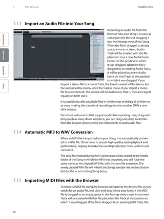
![73
Reference Manual
IntroductionReferenceAppendixIndex
file will be placed as a new Instru-
ment Part on the Track, at the posi-
tion to which it was dragged.
Some MIDI files will contain more
than one MIDI Part in the se-
quence. If this is the case, multiple
Parts will be shown when dragging
the file into your Song.
As with all Instrument Tracks, you
will need to ensure the new Instru-
ment Track is routed to a virtual
or external instrument in order
to hear the new Instrument Part. Refer to the Monitoring an Instrument
Track section of the“Recording”chapter for more information.
You can also drag a MIDI file directly onto virtual instruments that sup-
port drag-and-drop MIDI importing.
7.1.6 Export a MIDI File
To export an Instrument Part to a MIDI file, [Right]/[Control]-click on the
Part and select Export Instrument Parts. Choose a file name and storage
location in the pop-up menu and click OK. A Standard MIDI File will be
created with a .MID file extension.
Multiple Instrument Parts can be exported at once to a single file. To do
this, select the desired Parts and use the same process as above. One MIDI
file will be created that includes individual MIDI clips for each Part, in the
correct sequence, with a common start time.
Standard MIDI Files exported from Studio One can be used by virtually
any application that supports MIDI.
7.1.7 Make Finding Your Favorite Files Easy
It is common that groups of files, such as drum loops, are stored in one
folder on the computer. If you know you will constantly access such
folders in the Browser, you can create Tabs for these locations. By default,
there is only one Tab at the top of the File Browser, called“Files.”
To create a Tab for any file location, navigate to that location and select
either the location folder, or any file within that folder. Then [Right]/
[Control]-click on the location, select New Tab From Here in the pop-up
menu, and a new Tab will appear at the top of the File Browser with the
name of the folder, allowing instant
access.
You can rename a Tab if you don’t
want to use the default name. To
The Browser 7](https://image.slidesharecdn.com/4cee09e1-25e7-4441-8b08-e26836a7f5f4-160215210245/85/Music-Computing-StudioBLADE-Gen-3-Manual-Full-158-320.jpg)
![74
Studio One
IntroductionReferenceAppendixIndex
7 The Browser
rename a Tab, [Right]/[Control]-click on the tab and select Rename Tab.
Type a new name in the pop-up menu and click OK.
Tabs you create in the File Browser will appear for all Songs and Projects,
and you can create as many Tabs as you need. When the Browser runs
out of space for Tabs to be displayed, a dropdown list is created to the far
right of the Tab bar. Click on the Tab drop-down button to choose a Tab
from the list.
To close or remove Tabs, [Right]/[Control]-click on the desired Tab and
select Close Tab from the pop-up menu. To move up one level in the File
Browser, [Right]/[Control]-click and select“Up.”
7.2 The Pool
When audio is recorded on an
Audio Track, or when an audio
file is imported, an Audio Event is
created in the Arrange view of the
Song, and a representation of the
original audio file associated with
the Event, called a Clip, is placed in
the Pool. The Pool will thus contain
all audio files that are at any point
associated with an Audio Event in
your Song.
To open the Pool, first open the
Browser by clicking the Browse
button, then click on the Pool but-
ton.You also can press [F10] on the
keyboard to open the Pool directly.
7.2.1 Navigate the Pool
The Pool displays audio Clips as waveforms. These Clips can be sorted
using the Sort By menu at the top of Pool. The following Sort By options
are available:
Flat:•• View all Clips with no order.
Track:•• View Clips by the Track on which they are currently used or were
previously, used.
Type:•• View Clips by Clip Type (Audio or Sounds)
Location:•• View Clips by the storage location in which they exist on your
computer.
Record Take:•• View Clips by the order of record takes within your Song.](https://image.slidesharecdn.com/4cee09e1-25e7-4441-8b08-e26836a7f5f4-160215210245/85/Music-Computing-StudioBLADE-Gen-3-Manual-Full-159-320.jpg)
![75
Reference Manual
IntroductionReferenceAppendixIndex
7.2.2 Use Audio Files from the Pool
The audio Clip associated with any Event in your Song will always be
available in the Pool, regardless of whether the Events associated with
that Clip remain in the Arrange view of the Song. This means that the
original state of a Clip with which an Event is associated can be quickly
restored by loading it directly from the Pool.
Click-and-drag any Clip from the Pool into the Arrange view, as you
would when importing any file from the Browser.
7.2.3 Import Audio Files to the Pool
If you know a certain set of files will be used in a Song but do not want to
import them into the Song directly, you can simply import the files into
the Pool. Later, you can quickly import files from the Pool. If you want
copies to be placed in the Song’s Media folder when you import files into
the Pool, [Right]/[Control]-click in the Pool and select Copy External Files
from the pop-up menu. This ensures that all of the elements of your Song
are contained in the Song folder.
To import a file into the Pool, [Right]/[Control]-click on it in the File
Browser and select Import to Pool. Alternatively, you can simply drag files
from Windows Explorer or the Mac Finder into the Pool.
7.2.4 Copy External Files to the Song Folder
If audio loops and other files used in your Song are stored in many differ-
ent file locations on your computer, it can be difficult to find them, espe-
cially if files are moved or deleted. Scattered files also make it difficult to
back up your Song and all of its contents to a single location or to share
your Song with a collaborator.
To quickly copy all external files used in your Song to the Song’s Media
folder, [Right]/[Control]-click in the Pool and select Copy External Files
from the pop-up menu. Only those files that did not previously exist in
the Song folder will be copied and placed into the Media folder.
7.2.5 Backup or Share Your Song
Once all of the external files have been copied to your Song folder, you
can back up your Song and all of its contents simply by copying the Song
folder to an external hard drive or DVD. To share your Song with another
Studio One user, you can simply compress the Song folder in a .zip or .sit
archive, and then email or transfer the archive.
It’s unwise to rely on a compressed archive for backup, as future compat-
ibility with the archive type is uncertain, and file-write errors could lead
to an unusable archive. The best practice is to create a Wave file for every
track in your Song and store these files, uncompressed, along with the
original Song file.
The Browser 7](https://image.slidesharecdn.com/4cee09e1-25e7-4441-8b08-e26836a7f5f4-160215210245/85/Music-Computing-StudioBLADE-Gen-3-Manual-Full-160-320.jpg)
![76
Studio One
IntroductionReferenceAppendixIndex
7 The Browser
7.2.6 Useful Pool Commands
[Right]/[Control]-click in the Pool Browser window to select from the fol-
lowing commands:
Rename File: Rename the currently selected Clip.••
Locate File: Locate a file for the currently selected Clip (e.g., to find a••
missing file).
Show in Explorer: Open the file location for the currently selected Clip••
in Windows Explorer/Mac Finder.
Select on Track: Select any Events associated•• with the currently selected
Clip in the Arrange view.
Remove from•• Pool: Remove the currently selected Clip from the Pool.
This does not delete the file.
Delete File Permanently: Permanently delete the file associated with••
the currently selected Clip.
Convert Files: Convert selected files in the•• Pool to the current Song’s
sample rate and bit depth. The Convert Files menu will appear with file
options. A new file will be created for each selected file and placed in
the current Song’s Media folder.
Refresh: Refresh the contents list of the•• Pool to reflect the current state
of your Song and computer.
Locate•• Missing Files: If any files are missing in your Song—usually this
occurs because the files were moved—use this command to locate the
missing files.
Remove Unused Media: Remove any•• Clips from the Pool that are not
currently used in the Song. This will not delete the files.
Show Media Folder in Explorer: Open the Media Folder for the current••
Song in Windows Explorer or the Mac Finder.
7.3 Instruments and Audio Effects
The Browser makes finding and using your virtual Instruments and Audio
Effects fast and easy. The following describes this feature.](https://image.slidesharecdn.com/4cee09e1-25e7-4441-8b08-e26836a7f5f4-160215210245/85/Music-Computing-StudioBLADE-Gen-3-Manual-Full-161-320.jpg)
![78
Studio One
IntroductionReferenceAppendixIndex
7 The Browser
7.3.4 Instrument Presets
The presets for Studio One’s built-
in virtual instruments, including
Impact, SampleOne, and Presence,
can be loaded into your Song in
the same way as the instruments.
Drag-and-drop a preset from the
Browser to load the instrument
into your Song, with that preset
already loaded. Alternatively, when
the instrument is open, you can
load any preset for that instrument
by simply double-clicking on the
preset in the Browser or by clicking on the preset to select it and then
hitting [Return].
7.3.5 Browse for Audio Effects
Click on the Effects tab in the Browser or press [F7} on the keyboard to
find your Audio Effects.
7.3.6 Sort the Audio Effects View
You can sort the list of Audio Effects to help you find what you are look-
ing for. Click on the Sort By window at the top of the Browser to sort by
the following:
Flat: Sorts the effects in alphabetical order in a continuous list.••
Folder: Sorts the effects based on the storage location folders in which••
they reside.
Vendor: Sorts the effects in folders by vendor.••
Category: Sorts the effects in folders by the type of plug-in (Native,••
VST2, VST3, AU, FX Chains).](https://image.slidesharecdn.com/4cee09e1-25e7-4441-8b08-e26836a7f5f4-160215210245/85/Music-Computing-StudioBLADE-Gen-3-Manual-Full-163-320.jpg)
![79
Reference Manual
IntroductionReferenceAppendixIndex
7.3.7 Drag an Audio Effect into your Song
Audio Effects can be dragged into your Song in a number of ways, with
slightly different results. To load an effect on an existing Audio Track,
drag-and-drop the effect from the Browser onto the Track in the Arrange
view.You can also drag-and-drop an effect onto any Channel in the Con-
sole. If you prefer, you can even drag-and-drop an effect from the Browser
directly into a particular position in the Insert Device Rack of any Channel.
To create a new FX Channel in the Console with a particular effect pre-
loaded, drag-and-drop the effect from the Browser into any blank space
in the Console. The new FX Channel will automatically be given the name
of the effect.
7.3.8 Audio Effects Presets and FX Chains
The presets for Studio One’s built-
in Audio Effects can be loaded
into your Song in the same way as
third-party Audio Effects. Drag-
and-drop a preset from the Brows-
er into your Song to load the effect
with that preset. Alternatively, if
an Audio Effect is open, you can load any preset for the effect by double-
clicking on the preset in the Browser or by clicking on the preset to select
it and then hitting [Return]. FX Chains can be loaded in the same way,
as described in the FX Chains section of the“Mixing”chapter. This makes
configuring even the most complicated mix quick and easy.
7.4 Sound Sets
The audio loops, samples, and instrument presets included with Studio
One are bundled into Sound Sets and can be quickly located and used
by clicking on the Sound Sets tab in the Browser. The Sound Sets and are
carefully organized to make finding what you want very easy.
7.5 Browsing Song and Project Content
When working in a new Song or Project, incorporating previously used
elements can be helpful in a variety of ways. For instance, you may want
to reuse a particular synth sound or Instrument Part, or perhaps you want
to use a particular effect setting or chain of effects on a channel. Brows-
ing the contents of previously created and saved Songs and Projects is a
quick and easy way to find reusable material.
The Browser 7](https://image.slidesharecdn.com/4cee09e1-25e7-4441-8b08-e26836a7f5f4-160215210245/85/Music-Computing-StudioBLADE-Gen-3-Manual-Full-164-320.jpg)
![80
Studio One
IntroductionReferenceAppendixIndex
7 The Browser
To browse previously created Song content, open the Files tab in the
Browser and navigate to the Content folder (which contains all of your
Songs, Projects, and associated files, by default) or to the location you
have chosen for these files. Open the Song or Project folder to view the
Song or Project file and then [Right]/[Control]-click on this file and select
Show Package Contents from the pop-up menu.
The file will then have a navigation arrow next to it that, when clicked,
will expose one or two folders—Performances and Presets— depending
on the contents of the Song or Project. The Performances folder contains
all Instrument Parts recorded in a Song, which are saved as an internal
“.music”file type. The Presets folder contains a Channels folder that stores
the current settings for each audio effect used and an Instruments folder
that contains the settings for any virtual instruments.
Simply click-and-drag any of this content directly from the Browser into a
new Song or Project.
7.6 Importing Other Application Project Files
Studio One can open several other application project-file types. These
include PreSonus Capture Sessions (.capture), Steinberg Cubase Track Ar-
chives (.xml), Steinberg Sequel Projects (.steinberg-project), Kristal Audio
Engine Projects (.kristal), and Open TL (.tl). To open any of these project-
file types in Studio One, navigate to File/Open and select the desired file.](https://image.slidesharecdn.com/4cee09e1-25e7-4441-8b08-e26836a7f5f4-160215210245/85/Music-Computing-StudioBLADE-Gen-3-Manual-Full-165-320.jpg)
![81
Reference Manual
IntroductionReferenceAppendixIndex
8 Arranging
Arranging can entail repositioning recorded or imported audio and musi-
cal data to change the song structure, inserting tempo or time-signature
changes, and many other processes. The following chapter discusses
aspects of arranging in Studio One, including importing files, working
with audio loops, the Tempo Track, and more.
8.1 Quickly Duplicating Events
Events are often copied and pasted across a certain region to quickly
build an arrangement. For instance, you might want a one-bar drum
loop to continue for eight bars, or you might want a 4-bar synth melody
to continue for the next 12 bars.You can use the Duplicate function to
quickly copy and paste any Event in this fashion.
To Duplicate any Event, select it and press [D] on the keyboard. The
results are affected by the current Arrange view Snap and Timebase set-
tings. With Snap disengaged, the Event will be copied and a new instance
of the Event will be placed precisely at the end of the original Event . With
Snap engaged, when an Event is duplicated, the new in-
stance of the Event will be placed at the next logical Snap
position. For example, an Event approximately one bar in
length will be placed at the beginning of the next bar, whereas an Event
one-half bar in length would be placed at the next half-bar.
Press [D] on keyboard multiple times to quickly copy and paste a se-
lected Event across any region. If multiple Events are selected, they can
all be duplicated simultaneously in the same way as a single Event. For
instance, you could duplicate an entire verse and chorus for 24 tracks in a
few seconds. This is often done to build a rough arrangement of a Song,
after which unique parts for each section are later recorded.
To understand the Duplicate function in Studio One, experiment with
Events of various lengths and with various Snap and Timebase settings in
the Arrange view.
8.2 Duplicating Tracks
Tracks can also be easily duplicated, with or without the Events they
contain. To duplicate a Track, select the Track or any Event it contains and
then select Duplicate from the Track menu. This will duplicate the Track
and all of its settings, including Inserts and Sends.
If you want the Events the Track contains to be duplicated as well, select
Duplicate with Events from the Track menu. If multiple Tracks are selected
when the Duplicate Tracks function is used, each of the selected Tracks
will be duplicated.
Arranging 8](https://image.slidesharecdn.com/4cee09e1-25e7-4441-8b08-e26836a7f5f4-160215210245/85/Music-Computing-StudioBLADE-Gen-3-Manual-Full-166-320.jpg)
![82
Studio One
IntroductionReferenceAppendixIndex
8 Arranging
Alternatively, you can duplicate selected Tracks by holding [Ctrl] on the
keyboard and clicking-and-dragging the Tracks up or down in the Track
Column. A horizontal blue line will appear in the Track Column while
dragging the Tracks to indicate the Duplicate function, as opposed to the
regular function of reordering Tracks in the Track Column.
8.3 Tempo Track
Many modern recordings sound mechanical, like a machine playing mu-
sic. This is often because the recording has a single, static tempo, whereas
the tempo in a natural performance tends to drift slightly. Interesting and
musical results can be achieved by varying the tempo in your recordings.
Using Tempo Changes will not affect your ability to sync recordings to the
tempo, as the click track and all other elements in Studio One will follow
the Tempo as it changes.
8.3.1 Inserting Tempo Changes
To insert a Tempo Change, open the Tempo Track by clicking on the
Tempo Track button above the Track Column. Then select the Draw Tool
in the Arrange View. Click at any position in the Tempo Track to insert a
Tempo Change and drag up or
down to adjust the Tempo value at
that position.
To change an existing Tempo value in the Tempo Track, float the Draw or
Arrow Tool to the top of the Tempo region and click-and-drag the tempo
value up or down (see Fig. 8-6).You can also click-and-drag the beginning
of any new Tempo region left or right across the Timeline to reposition
the tempo change in the Tempo Track (see Fig. 8-7).
The tempo value set by the Tempo Change will continue for the rest of
the Song or until the next Tempo Change. Also, the tempo value in the
Transport will be immediately updated at the appropriate time, according
to each Tempo Change.
8.4 Time Signature
The time signature is a convention used in Western music notation to
specify how many beats are in each bar and what note value constitutes
one beat. The time signature is notated as a fraction, where the numera-
tor (the upper number) equals the number of beats in the bar, and the
denominator (the bottom number) equals the note value for each beat.
By default, the time signature is set to 4/4 for all new Songs. This means
there will be four quarter-notes per bar. To change the time signature for
your Song, do one of the following:](https://image.slidesharecdn.com/4cee09e1-25e7-4441-8b08-e26836a7f5f4-160215210245/85/Music-Computing-StudioBLADE-Gen-3-Manual-Full-167-320.jpg)
![83
Reference Manual
IntroductionReferenceAppendixIndex
Click on upper or lower number of the time signature in the•• Transport
and select a new value from the pop-up menu.
Double-click on the•• Time Signature Marker to the far left of the Ruler in
the Arrange view and select new values from the pop-up menu.
••
Metronome behavior will be affected by the time signature. The down-
beat and other beats determine the sample and level used for the Accent
and Click respectively.
8.4.1 Inserting Time Signature Changes
It is possible that your Song requires more than one time signature, in
which case you will want to insert time-signature changes at various
places. To insert a time-signature change, [Right]/[Control]-click in the
Timeline ruler where you wish to insert the change and select Insert Time
Signature. Enter the values for the new time signature in the pop-up
menu and click OK, and a new Time Signature marker will be inserted at
that position.
You can click-and-drag a Time Signature marker to any bar-line position
in the Ruler; the time signature must change on a new bar. Double-click
on the Time Signature marker and choose new values to change the time
signature at that marker’s position.
Your Song can contain any number of time-signature changes, and the
current time signature is always displayed in the Transport.
8.5 Bouncing
8.5.1 Bouncing Instrument Parts
When working with musical-performance data, users often want to print
the audio being generated by external MIDI and internal virtual instru-
ments to audio so that the part can be treated like a normal Audio Track.
Studio One offers a special feature to accommodate this kind of workflow.
To quickly bounce any Instrument Part to an Audio Track, select the
Instrument Part, and then select Bounce Instrument Parts in the Event file
menu or simply press [B] on the computer keyboard. This will render the
Arranging 8](https://image.slidesharecdn.com/4cee09e1-25e7-4441-8b08-e26836a7f5f4-160215210245/85/Music-Computing-StudioBLADE-Gen-3-Manual-Full-168-320.jpg)
![84
Studio One
IntroductionReferenceAppendixIndex
8 Arranging
selected Instrument Part to a new Audio Event and place it at the correct
Timeline position on a new Audio Track.
When an Instrument Part is bounced, the Part will be muted, since the
new Audio Event is taking its place. The Instrument Part will be grayed
out to indicate this. To toggle the mute on the Part, select the part and
press [Shift]+[M] on the keyboard.
Any number of Instrument Parts can be selected and bounced to audio at
once, even across multiple Instrument Tracks. A new Audio Track will be
created for each Instrument Track whose Part is bounced to audio.
If you want to create a single Audio Event, you should first merge various
Instrument Parts on an Instrument Track to create a single continuous
Instrument Part. To do this, select the desired Parts and choose Merge
Instrument Parts, or press [G] on the keyboard.
8.5.2 Bouncing Audio Events
When many edits have been performed across an Audio Track to one
or multiple Audio Events, the arrangement can become difficult to look
at and hard to work with. For instance, if a drum loop has been cut into
many slices, with some parts duplicated, other parts deleted, and so on,
moving or rearranging the Events can become difficult.
In this case, it is helpful to render some or all of the contents of a Track to
a single, continuous new Audio Event. To do this, select the desired Audio
Events and press [Ctrl]/[Cmd]+B on the keyboard or select Bounce Selec-
tion from the Event menu. A new Audio Event will be created for each
Track that has an Event selected. The new Audio Events will be created
and placed according to the position and range of the selected Events for
each Track.
Note that the Bouncing Selection process is unaffected by Track Volume,
Pan, and Insert settings, as it is only dealing with the Audio Events exactly
as they exist in the Arrange view. Thus, the result of this process will not
affect what you hear; it is simply an organizational tool.
8.6 Adding Time to the Arrangement
It is often useful to insert a range of silence into an arrangement, effec-
tively adding time to a section. To do this, select the Range tool in the
Arrange view, then select a range across any tracks on which you wish
you insert silence. With the range selected, press [Ctrl]+[Alt]+[I] on the
keyboard to insert silence in that range.
Any events that were in the range where silence was inserted will be split,
if necessary, and moved to the right across the timeline.](https://image.slidesharecdn.com/4cee09e1-25e7-4441-8b08-e26836a7f5f4-160215210245/85/Music-Computing-StudioBLADE-Gen-3-Manual-Full-169-320.jpg)
![85
Reference Manual
IntroductionReferenceAppendixIndex
9 Mixing
Mixing is the part of the production process where all recorded and ar-
ranged material is balanced in relative volume, frequency, and dynamic
content in order to achieve a desired cohesive sound.
The following chapter discusses basic aspects of mixing in Studio One,
including the Console, the Channel types, and Inserts and Sends. For
more advanced mixing topics, such as Automation, please refer to the
later chapters.
9.1 The Console
Mixing in Studio One is primarily done in the Console. Open the Console
by clicking on the Mix button or by pressing [F3] on the keyboard.
Each channel of audio in your Song is represented by a Channel in the
Console. Audio Tracks in the Arrange view are directly represented by
Audio Channels in the Console, whereas Instrument Tracks have no direct
representation in the Console. Instead, Instrument Channels represent
the audio output of virtual instruments. There are several other Channel
types discussed below, including Input, Output, Bus, and FX Channels.
It is important to note that the Console opens by default in Small mode,
and the following descriptions assume this mode is engaged unless
otherwise noted. For more on this topic, refer to the Alternative Console
Layout section of this chapter.
9.1.1 Channel Features
Certain features are common to all Channels.
9.1.2 Input/Output
At the top of each Channel is a display of its configured input and output,
with the input shown at the top and the output shown at the bottom. All
Channels are configured with Main Out as their output by default.
Mixing 9](https://image.slidesharecdn.com/4cee09e1-25e7-4441-8b08-e26836a7f5f4-160215210245/85/Music-Computing-StudioBLADE-Gen-3-Manual-Full-170-320.jpg)
![86
Studio One
IntroductionReferenceAppendixIndex
9 Mixing
Audio Channels will show the hardware audio-input selection, and Bus
and FX Channels will display no input, as their input source is usually
from multiple channels. Instrument Channels will display the name of the
virtual instrument from which they get their input.
Click on any input or output to display and choose from a list of available
routing options for any Channel. Clicking on the Input for an Instrument
Channel will open the interface for the source virtual instrument.
9.1.3 Panner and Fader
All Channels feature a horizontal Panner and vertical Fader below the I/O-
selection display. The Panner can be clicked-and-dragged horizontally,
allowing the audio for each Channel to be positioned left or right in the
stereo field. The Fader can be click-and-dragged vertically to control the
output volume for each Channel.
9.1.4 Mute/Solo
Channels can be muted or soloed by clicking on their Mute and Solo
buttons, respectively.You can also press [M] for Mute or [S] for Solo on
the keyboard to mute or solo the selected Channels. Muting will silence
the Channel’s audio from the Console so you won’t hear it. Soloing will
silence all except the audio for the soloed Channel, so you will only hear
the soloed Channel. Any number of Channels can be muted or soloed
simultaneously.
You can perform a Global Solo Off, which disengages Solo on any track
that has it engaged, by pressing and holding [Ctrl] on the keyboard and
then clicking on any Solo button. Performing the [Ctrl]+Click again will
recall the previous solo settings, returning any previously soloed channels
to the solo state. This can be useful when comparing a group of soloed
tracks to other tracks in your mix.
9.1.5 Automation Mode
The Automation Mode for each Channel is displayed at the bottom of the
Channel. By default, this mode is set to Off. Click on this display to choose
an Automation Mode or to add and remove automation parameters.
9.1.6 Name
Channel names are shown at the bottom of each Channel in the Console.
Double-click on the name, type a new name, and then press Enter to
change the name of any Channel.](https://image.slidesharecdn.com/4cee09e1-25e7-4441-8b08-e26836a7f5f4-160215210245/85/Music-Computing-StudioBLADE-Gen-3-Manual-Full-171-320.jpg)

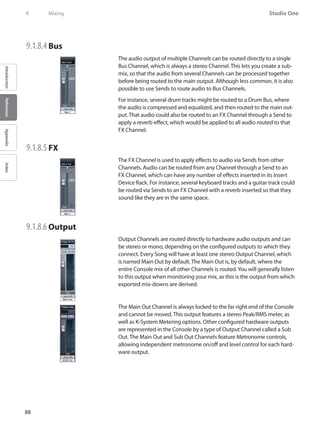
![89
Reference Manual
IntroductionReferenceAppendixIndex
9.1.9 Console Panel Overview
The Console features several panels that can be shown or hidden as
needed. Each panel has different functions and is accessed from the Con-
sole navigation column to the far left of the Console.
9.1.9.1 Inputs
The Inputs panel is closed by default and can be opened and closed by
clicking on the Inputs button in the Console navigation column. The In-
puts panel will display audio channels in the Console for each configured
hardware audio input as described in the Channel Types section of this
chapter.
9.1.9.2 Trash Bin
The Trash Bin panel is closed by default and can be opened and closed
by clicking on the Trash button in the navigation column. The Trash Bin
panel displays a list of removed Console objects, including channels,
virtual effects, and virtual instruments. Each object in the list will contain
the exact state of the entire channel, effect, or instrument when it was
removed, making it possible to restore previous settings and states in the
Console at any time.
To restore an object in the Trash Bin to its previous state and location in
the Console, [Right]/[Control]-click on it in the Trash Bin and select Re-
store from the pop-up menu. To permanently remove an object from the
Trash Bin, [Right]/[Control]-click on it in the Trash Bin and select Delete
from the pop-up menu.
9.1.9.3 External
The External panel is closed by default and can be opened and closed by
clicking on the External button in the navigation column. The External
Panel displays a list of configured External Devices, including Keyboards,
External Instruments, and Control Surfaces.
The configuration for each device can be accessed and edited by clicking
on the menu arrow for the device and selecting, from the pop-up menu,
either Edit for mapping configuration or Setup for device configuration.
Click on the Add External Device button to add an external device.
Mixing 9](https://image.slidesharecdn.com/4cee09e1-25e7-4441-8b08-e26836a7f5f4-160215210245/85/Music-Computing-StudioBLADE-Gen-3-Manual-Full-174-320.jpg)
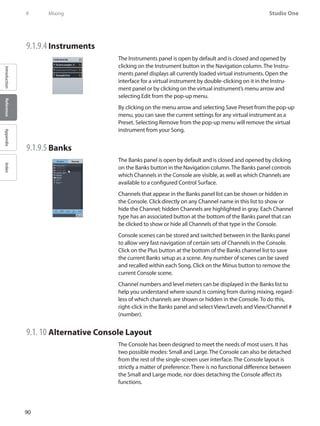
![91
Reference Manual
IntroductionReferenceAppendixIndex
9.1.11 The Large Console
To switch to the Large Console mode while in Small Console mode
(Console is in Small mode by default), click on the Maximize button at
the top of the Console Navigation column. Alternatively, you can press
[Shift]+[F3] on the keyboard when the Console is open.
In Large mode, you can see the
Insert and Send Device Racks at
the top of each Channel, allowing
faster access to these elements.
The lower portion of the Channel
is slightly larger as well, allowing
easier viewing of meters and other
elements.
9.1.12 The Detached Console
The Console can be detached from
the main window and placed in an
independent window so that it can
be located freely onscreen or on a
second computer monitor.
To Detach the Console, click on the Detach button at the top of the Con-
sole navigation column. The Detached Console can be in Small or Large
mode, and the window can also be sized and maximized to fit the com-
puter monitor. To reattach the Console to the main interface, click on the
Detach button at the top of the Console navigation column.
Mixing 9](https://image.slidesharecdn.com/4cee09e1-25e7-4441-8b08-e26836a7f5f4-160215210245/85/Music-Computing-StudioBLADE-Gen-3-Manual-Full-176-320.jpg)
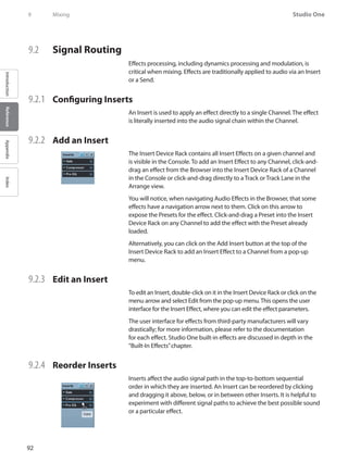
![93
Reference Manual
IntroductionReferenceAppendixIndex
9.2.5 Navigating Inserts
By default, only one window displays the user interface for an open Insert
Effect. This keeps screen clutter and window juggling to a minimum. To
quickly switch between Insert Effects on a single Channel, open one of
the Insert Effects and do one of the following:
Click on the left or right arrow at the top left of the Insert Effect window••
to step sequentially through the interface for each Insert on the Channel.
Click on the down arrow at the top left of the Insert Effect window and••
choose from the list of Inserts to select the interface for a specific Insert
on the Channel .
Float the mouse cursor over the down arrow at the top left of the Insert••
Effect window, then mouse-wheel up or down to step sequentially
through the interface for each Insert on the Channel.
Alternatively, press [F11] on the keyboard to open the effect editor for the
selected Audio Track, then press [Ctrl]+[Page Up]/[Page Down] to cycle
through the effects in that channel’s device rack.
By clicking on the Pin button in the upper right of the Insert Effect win-
dow, the interface for any Insert can be made to stay open in an indepen-
dent window until you choose to close it. With an Insert Effect Pinned,
opening another Insert Effect will open a new Insert Effect Window. Any
number of Insert Effect windows can be Pinned and open simultaneously.
9.2.6 Copy an Insert to Another Channel
It is often helpful to be able to copy an Insert Effect, including its cur-
rent settings, to another Channel. To do this, click on the desired Insert
Effect in the Insert Device Rack and drag it directly onto any other Chan-
nel or into the Insert Device Rack on any other Channel. Dragging an
Insert Effect to the left or right edge of the viewable Console will scroll
the Console left or right to expose any Channels beyond those currently
viewable.
9.2.7 Deactivate an Insert
To deactivate, or turn off, an Insert Effect, click on the Activate button for
the Insert Effect in the Insert Device Rack. There is also an Activate but-
ton at the top left of every Insert Effect window. The Activate button will
turn gray when the Insert Effect is switched off and blue when it is active
(turned on). Deactivating an Insert Effect will stop any and all processing
related to it, which frees the computer processing resources previously
dedicated to that Insert Effect.
To deactivate or activate all Insert Effects in any Insert Device Rack, click
on the Activate All button at the top of the Insert Device Rack.
Mixing 9](https://image.slidesharecdn.com/4cee09e1-25e7-4441-8b08-e26836a7f5f4-160215210245/85/Music-Computing-StudioBLADE-Gen-3-Manual-Full-178-320.jpg)
![95
Reference Manual
IntroductionReferenceAppendixIndex
Alternatively, you can create an FX Channel by [Right]/[Control]-clicking
in blank space in the Console, or on any channel, and selecting Add FX.
This will add an FX Channel to the Console with no inserts, which can be
the destination for any Send.
FX Channels can only output to the Main Out channel of the Console.
To quickly view the effects in the Insert Device Rack of a Send destina-
tion Channel, double-click on the Send.You can then navigate the Insert
Effect window as usual.
9.2.12 Send Level and Pre/Post Fader
Once a Send has been added to a Channel, the send device will appear in
the Send Device Rack for that Channel.You will find an Activate button,
horizontal Level and Pan faders, and a Pre/Post Fader button. Click on the
Activate button to activate/deactivate the Send; this does not affect the
Send’s destination Channel.
Click-and-drag on the horizontal Level fader to adjust the Send level
between -∞ and +10 dB. Click-and-drag on the Pan fader to adjust the
balance of the source material going to the Send destination. Click on the
Pre/Post Fader button to switch the Send source to pre-fader or post-
fader. Pre-fader allows you to set a Send level independent of the channel
fader so that the level is unaffected by fader position.
The Send source signal is always post-inserts.
9.2.13 Sidechaining
Certain effects can accept an input from an audio source that dynamically
changes the behavior of the effect. This is called“sidechaining,”and it fa-
cilitates processes such as keying, ducking, and de-essing. Sidechaining is
accomplished by using a Send to route audio to a special Sidechain input
on an Insert Effect.
It is possible to send to the Sidechain input of any Insert Effect, whether
or not the sidechain is engaged in the effect. For the sidechain to work in
the effect, it must be engaged in the effect.
An example of sidechaining is when a gate is triggered by a specific audio
signal. In this case, the gate will open and close dynamically in response
to the audio signal coming in the sidechain, rather than responding to
the program signal on the Channel where the Gate is inserted. Several of
Studio One’s included built-in effects support sidechaining, including the
Compressor and Gate. For more information, refer to the“Built-In Effects”
chapter.
Mixing 9](https://image.slidesharecdn.com/4cee09e1-25e7-4441-8b08-e26836a7f5f4-160215210245/85/Music-Computing-StudioBLADE-Gen-3-Manual-Full-180-320.jpg)
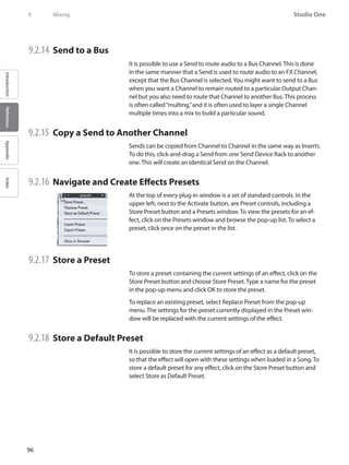
![97
Reference Manual
IntroductionReferenceAppendixIndex
9.2.19 Use Presets to Build a Unique Sound
Studio One’s preset system is very easy to use. If you take the time to load
plug-in presets and tweak them even a little bit, then save your person-
alized sounds as unique presets in Studio One, you can build a distinc-
tive library. After that, you can quickly locate your custom presets in the
Browser; no digging through every preset just to find the one you want.
9.2.20 FX Chains
You may wish to insert certain combinations of effects together on a
Channel. For instance, you might regularly apply a compressor, EQ, and
chorus to your vocal tracks.
In Studio One, FX Chains are used to save the exact setup of an Insert
Device Rack so that the entire chain of effects, including all settings, can
be recalled instantly. To create an FX Chain:
Configure an Insert Device Rack on a Channel with the desired effects••
and settings.
Click on the menu arrow at the top of the Insert Device Rack, next to••
the Insert label, and select Save Preset from the pop-up menu.
Type in a unique name for the FX Chain and click OK or press [Enter] on••
the keyboard.
••
FX Chains can be found in the FX Chains folder in the Audio Effects
Browser. To insert the FX Chain in the Insert Device Rack of a Channel,
drag any FX Chain from the Browser to the Channel.
Click on the menu arrow next to the FX Chain name in the Audio Effects
Browser to view and select the individual effects.You can then click on
the menu arrow next to each effect name within the FX Chain to view the
presets used for each effect in the FX Chain. Both the individual effects
and each preset can be dragged to the Insert Device Rack of any Channel.
It is also possible to access FX Chains from the Insert Device Rack by click-
ing on the menu arrow at the top of the Rack and selecting an FX Chain
from the list. This will load the selected FX Chain in the Insert Device Rack
.
Mixing 9](https://image.slidesharecdn.com/4cee09e1-25e7-4441-8b08-e26836a7f5f4-160215210245/85/Music-Computing-StudioBLADE-Gen-3-Manual-Full-182-320.jpg)
![98
Studio One
IntroductionReferenceAppendixIndex
9 Mixing
9.2.21 Busing
Buses can be extremely useful
when mixing.You can route Chan-
nels directly to Buses to help orga-
nize a mix into common elements,
such as routing all Drum Tracks
directly to a drums bus. Sends are
often used to route a channel to
multiple buses in order to layer a signal into various elements of a mix.
To create a new Bus, [Right]/[Control]-click in blank space in the Console,
or on any Channel, and select Add Bus.You can then choose that bus as
the Output or Send destination for any Audio or Instrument Channel in
the Console. The Bus sends its summed signal to the Main Out by default
but can also be routed to Sub Out Channels. Buses have sends that can
be used the same way as other sends in Studio One.
9.2.22 Save Solo:
It is possible to place Console channels in Save Solo mode. When any
channel in the Console is soloed, all channels with Save Solo engaged are
also soloed, and all other channels are muted. To engage Save Solo on
any channel, [Shift]+Click on its solo button in Console. The Solo button
will change color to show Save Solo is engaged.
Note that FX Channels have Save Solo engaged by default because ef-
fects may be critical to how soloed channels sound in the mix, so when
any channel is soloed, you will probably want to hear the applicable FX
Channel output as well.
9.3 Groups
As discussed in the Edit Groups section of the“Editing”chapter, it is
possible to group multiple tracks together so that any edits done to an
Event on one track in the group are automatically done to all Events for
all Tracks in the group. These same Edit Groups affect how their related
Channel Faders will behave in the Console.](https://image.slidesharecdn.com/4cee09e1-25e7-4441-8b08-e26836a7f5f4-160215210245/85/Music-Computing-StudioBLADE-Gen-3-Manual-Full-183-320.jpg)
![99
Reference Manual
IntroductionReferenceAppendixIndex
9.3.1 Create or Dissolve a Group in the Console
To create a Group in the Console, select the desired Channels and then
[Right]/[Control]-click and select Group Selected Tracks from the pop-up
menu. To dissolve, or ungroup, grouped Channels in the Console, [Right]/
[Control]-click on any Channel in the Group and select Dissolve Group
from the pop-up menu.
When a Channel is in a Group, the Group icon will appear on the Channel.
9.3.2 Group Behavior in the Console
When a Channel is placed in a Group, its fader will be linked to the faders
for all other Tracks in the Group, so that all of the faders will move when
any of them is moved. The movement of faders in the Group will be
relative to one another, maintaining the correct dB value relationships
among the faders. Note that Channel Pan is not affected by grouping, as
channels within a group are very often panned separately.
Solo, Mute, Record Enable, and Monitor Enable controls will also be linked
for all Channels in a Group. No other aspect of the Channel in the Console
is affected by grouping.
Instrument Tracks in the Arrange view have no direct representation in
the Console. The audio outputs of the virtual instruments to which they
are routed will have Channels in the Console. It should be noted, how-
ever, that grouping Instrument Tracks in the Arrange view only affects
editing those Tracks and has no effect on the Instrument Channels for the
virtual-instrument audio outputs.
9.3.3 Temporarily Suspend Groups
It is possible to temporarily suspend a Group so that, for instance, the
fader for a Channel in a Group can be edited without affecting the other
Channels in the Group. To suspend the Group, hold [Alt]/[Option] on the
keyboard while clicking on the Fader, Mute, Solo, Record Enable, or Moni-
tor Enable controls.
9.4 Metering
Metering is a critical part of the production process. Studio One’s meters
visually display audio levels that closely correspond with perceived loud-
ness, and you can meter these levels at various stages in the signal path.
Peak meters can be found on every Channel in the Console except the
Output Channels, which appropriately feature a more informative Peak/
RMS meter with K-System Metering options.
Mixing 9](https://image.slidesharecdn.com/4cee09e1-25e7-4441-8b08-e26836a7f5f4-160215210245/85/Music-Computing-StudioBLADE-Gen-3-Manual-Full-184-320.jpg)
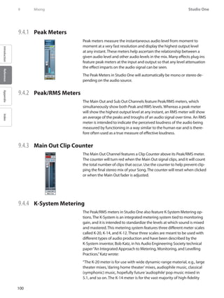
![101
Reference Manual
IntroductionReferenceAppendixIndex
productions for the home, e.g., home theater and pop music (which
includes the wide variety of moderately compressed music, from folk
music to hard rock). And the K-12 meter is for productions to be dedi-
cated for broadcast.”
To switch to any K-System meter, [Right]/[Control]-click on any Peak/RMS
meter and choose an option from the menu.
When using any of the three K-System scales, the 0 VU mark should be
calibrated to 85 dB SPL from your monitors, which you should measure
with an SPL meter. For instance, playing back a -14 dBFS sine wave in Stu-
dio One while using the K-14 scale will cause the meter to read 0 VU for
both the peak and average levels, and your monitors should be adjusted
so that the SPL meter at the listening position reads 85 dB SPL.
9.5 Automatic Plug-In Delay Compensation
Some plug-in effects inherently have some delay, or latency. It takes a
certain amount of time for these plug-ins to process the audio routed to
them, which means the resulting output audio is slightly delayed. This es-
pecially applies to dynamics-processor plug-ins that feature a look-ahead
function, such as the included Compressor.
In Studio One, this inherent delay is managed with Plug-in Delay Com-
pensation through the entire audio path. There are no settings to man-
age, as this feature is completely automatic. The sync and timing of every
audio channel in your Song are automatically maintained, no matter
what processing is being used.
The current total Plug-in Delay time is displayed in the left side Transport,
below the current sample rate.
If you desire, you can turn off Plug-in Delay Compensation by select-
ing Ignore Plug-in Delay in the Transport file menu. When this mode is
selected, the sync of all audio channels will need to be handled manually
by adjusting Event positions or Track Delay times in the Track Inspector.
9.6 Manual Audio Track Delay
It is sometimes necessary to manually delay the playback of audio to
keep it in sync with other audio. A classic example is in the case of re-
cording a live performance, where tracks are recorded directly from the
mixing console, while ambient microphones capture the audience sound
from a position well away from the stage. The direct sound from the con-
sole arrives at the recorder almost instantaneously; it takes longer for the
sound to reach the ambient mics from the stage. When the signals are
mixed, the time difference results in audible delay and phase problems.
To properly align the recorded audio from the ambient mics with the rest
of the recorded mix, you can apply a negative amount of manual delay to
the ambient recording.
Mixing 9](https://image.slidesharecdn.com/4cee09e1-25e7-4441-8b08-e26836a7f5f4-160215210245/85/Music-Computing-StudioBLADE-Gen-3-Manual-Full-186-320.jpg)
![102
Studio One
IntroductionReferenceAppendixIndex
9 Mixing
Open the Inspector view by clicking on the Inspector button or pressing
[F4] on the keyboard. Enter a positive or negative Delay value, in millisec-
onds, to apply a delay to the Track.
To calculate the value to apply to ambient mics in the example, do the
following:
Measure the distance from the stage to the ambient mics.••
Divide the distance in feet by 1,129, which is roughly the speed of••
sound in feet/second. (Divide the distance in meters by 343 for me-
ters per second.) The resulting value is the amount of seconds it
took for sound to reach your ambient mics. For example, if the dis-
tance was 100 feet, the resulting amount of time is 0.0885 seconds
(100/1,129=0.0885), or 88.5 milliseconds.
For the stereo ambient mic Track, or for each mono Track, you will enter••
a Delay value of -88.5, which removes the recorded delay and puts the
Tracks in sync with the rest of the recording.
9.7 Using the Marker Track
You’ll probably want to quickly navigate to various areas of your Song
during mixdown. In Studio One, the Marker Track is used to place Markers
at desired places in the timeline, after which navigation to the Markers is
easy. To open the Marker Track, click on the Marker Track button above
the Track Column in the Arrange view.
Notice the Timebase button to the right of the Marker Track in the Track
column. The musical-note icon on the Timebase button indicates that
Markers will adhere to their position based on Bars and Beats, so if the
tempo changes, the Markers will move forward or backward in time in
relation to their musical position.
If you click on the Timebase button, it will switch to a clock icon, indicat-
ing that the Markers will adhere to their absolute position in time. If the
tempo changes, the Markers will not move, as they are locked to an abso-
lute time position in the timeline.
9.7.1 Inserting Markers
To insert a new Marker into the Marker Track, with playback running
or stopped, click on the Add Marker button or press [Insert]/[Y] on the
keyboard. Each new marker will be numbered sequentially by default (1,
2, 3…). To rename a Marker, double-click on it in the Marker Track, type in
a new name, and then press [Enter] on the keyboard.](https://image.slidesharecdn.com/4cee09e1-25e7-4441-8b08-e26836a7f5f4-160215210245/85/Music-Computing-StudioBLADE-Gen-3-Manual-Full-187-320.jpg)
![103
Reference Manual
IntroductionReferenceAppendixIndex
9.7.2 Navigating Markers
You can quickly jump the Playback Cursor between Markers in the Marker
Track. Click on the Previous Marker button in the Transport, or press
[Shift]+B on the keyboard, to jump to the previous Marker. Click on the
Next Marker button in the Transport, or press [Shift]+N on the keyboard,
to jump to the next Marker. Jumping to Markers during playback enables
quick comparisons between sections of your Song.
You can also jump to up to seven different markers from the Transport/
Goto Marker menu.
9.7.3 Song Start and End Markers
When a new Song is created, you can specify a Song Length. The default
length is 5 minutes or 151 bars at the default 120 bpm tempo. At the be-
ginning and end of the specified region, Song Start and End Markers are
automatically placed in the Marker Track. These markers can be used in
the Export to Audio File menu to define the timeline region to be export-
ed, and they are used by default in the Update Mastering File process.
9.8 Looping During Mixing
Looping a section of audio (for instance a chorus) while mixing allows
you to focus on a particular area of your overall Song without having to
constantly stop, rewind, and resume playback.
To quickly loop a section of audio,
first select the audio you want to
loop by either selecting a range
with the Range Tool or directly selecting an Event or multiple Events
with the Arrow Tool in the Arrange view. Then press [P] on the keyboard
to set the Left and Right Locators around your selection. Alternatively,
press [Shift]+P on the keyboard to ignore Snap while setting the Locators.
Finally, click on the Loop button in the Transport, or press [Num Pad /] on
the keyboard, to loop the playback between the Left and Right Locators.
Alternatively, you can manually set the Left and Right Locators to a de-
sired range and then engage Loop in the Transport. To do this, float the
mouse cursor to the top of the Timeline Ruler until you see the Draw Tool
appear. Then click-and-drag to the right to draw the loop region (Left and
Right Locators) around the area you wish to loop and engage Loop in the
Transport.
You can also manually move the Left and Right Locators by clicking and
dragging them left or right in the Timeline Ruler.
Mixing 9](https://image.slidesharecdn.com/4cee09e1-25e7-4441-8b08-e26836a7f5f4-160215210245/85/Music-Computing-StudioBLADE-Gen-3-Manual-Full-188-320.jpg)
![104
Studio One
IntroductionReferenceAppendixIndex
9 Mixing
9.9 Mixing Down
Most often, you’ll record multiple tracks in each Song, but you will need
to mix these tracks to stereo for distribution on CD, DVD, or the Web. With
a DAW such as Studio One, this simply means saving your mix to a stereo
file.
9.9.1 Create a Mix
To create a mix of your Song in Studio One, navigate to Song/Mixdown to
Audio File or press [Ctrl]/[Cmd]+E on the keyboard to open the Export to
Audio File menu (see Fig. 9-41).
9.9.2 Location
The top section of the Mixdown to Audio File menu is where you will
select a location and name for the mix file. Click on the Location button to
choose a file location. Double-click on the filename, type in a new name,
and press [Enter] to choose a name for the file.
9.9.3 Format
Select the format for your mix file in the middle section of the Export to
Audio File menu. Choose from Wave, AIFF, Ogg Vorbis, or MP3 file, and
then choose the desired resolution and sample rate.
If you want to put your mix on a standard audio CD, create a 16-bit,
44.1 kHz Wave file.
9.9.4 Options
The bottom section of the Export to Audio File menu has several options
that affect how the mix file is created.
Choose from Export Loop Range or Export between Song Start/End
Marker. The Export Loop Range option will only export the range of your
Song between the Left and Right Locators. Export between Song Start/
End Marker will export the range of your Song between the Song Start
and End Markers, as seen in the Marker Track.The duration of the range to
be exported is displayed in the Duration field.](https://image.slidesharecdn.com/4cee09e1-25e7-4441-8b08-e26836a7f5f4-160215210245/85/Music-Computing-StudioBLADE-Gen-3-Manual-Full-189-320.jpg)
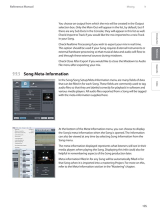
![106
Studio One
IntroductionReferenceAppendixIndex
9 Mixing
9.10 Export Individual Tracks from your Song
It can be helpful to quickly export individual tracks from your Song. For
instance, you might wish to send the tracks to someone who will prepare
a different mix or remix the Song. The Export Tracks as Audio Files feature
in Studio One provides an easy way to accomplish this.
9.10.1 Select Tracks
To export tracks from your Song in Studio One, navigate to Song/Export
Tracks as Audio Files to open the Export Tracks as Audio Files menu. Once
in this menu, select the tracks you wish to export by checking each track
in the list on the left.
Note that the audio file created for any selected track will be the equiva-
lent of putting the track into solo in the Console and listening to the
result. The audio file will include the results of all inserts and sends on
the track. If you don’t want the inserts or sends included in the exported
tracks, disable them (or mute FX channels and Bus channels, as neces-
sary) before exporting the tracks as audio files.
9.10.2 Location
You can select a location and name for the exported files in the top sec-
tion of the Export Tracks as Audio Files menu. Click on the Location but-
ton to choose a file location. Double-click on the filename, type in a new
name, and press [Enter] to choose a name for the file. The name of each
track in the Song that is being exported will be appended to the user-
specified filename.
9.10.3 Format
Select the format for your mix file in the middle section of the Export
Tracks as Audio Files menu. Choose from Wave, AIFF, FLAC, Ogg Vorbis, or
MP3 and then choose the desired resolution and sample rate.
9.10.4 Options
The bottom section of the Export Tracks as Audio Files menu has several
options that affect how the files are created.
Select a time range to export by selecting Loop, Between Song Start/End
Marker, Between Each Marker, or Between Selected Markers. The Export
Loop Range option will only export the range of your Song between
the Left and Right Locators. Export Between Song Start/End Marker will
export the range of your Song between the Song Start and End Markers,
as seen in the Marker Track.](https://image.slidesharecdn.com/4cee09e1-25e7-4441-8b08-e26836a7f5f4-160215210245/85/Music-Computing-StudioBLADE-Gen-3-Manual-Full-191-320.jpg)
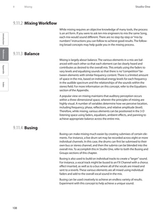
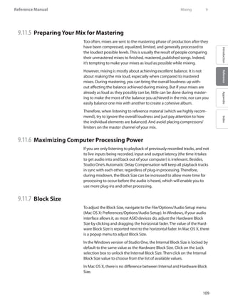
![110
Studio One
IntroductionReferenceAppendixIndex
9 Mixing
9.11.8 Rendering and Deactivating Virtual Instruments
Virtual instruments can require a lot of computer resources, which limits
the computing power that’s available for other processes. Therefore, it is
sometimes worthwhile to render the audio output of an Instrument Track
to an Audio Track, and then deactivate the virtual instrument. Do the fol-
lowing to accomplish this:
Select all of the Instrument Parts on the Instrument Tracks that you••
would like to render to audio.
Select Bounce Instrument Parts from the Event menu or press [B] on the••
keyboard. Each Instrument Part will be rendered to an Audio Event and
placed appropriately on a new Audio Track.
•• Click on the Instrument icon on the Instrument Tracks to open the user
interface for its virtual instrument and click on the Activate button to
deactivate it. This will free any computer resources previously being
used by the virtual instrument.
The same concept applies to resource-intensive Audio Effect plug-ins.
You can export audio to a new track using the Song/Export to Audio File
menu, then remove the pre-rendered audio track.
9.11.9 Audio Engine Overload
Computers have a limited amount of processing power, and you can
reach a point where the system can’t support all of the running processes.
If this occurs while using Studio One, the Studio One audio engine will
overload, causing the application to become unresponsive or frozen.
If this happens, and Studio One becomes unresponsive for more than
15 seconds, the system is automatically stopped, and the audio device is
suspended. A warning message will be displayed to notify you this has
happened.
When you see this message, immediately save your Song or Project. After
saving, disable some plug-ins, including Audio Effects and virtual instru-
ments, to reduce the amount of computer processing needed to play the
Song or Project. When you resume playback, the audio engine will func-
tion normally. If you see the warning again, try disabling more plug-ins.
This feature is intended to make the experience of using Studio One
stable and enjoyable on less-powerful computers. If you are using a
relatively powerful computer, you will probably never overload the audio
engine.](https://image.slidesharecdn.com/4cee09e1-25e7-4441-8b08-e26836a7f5f4-160215210245/85/Music-Computing-StudioBLADE-Gen-3-Manual-Full-195-320.jpg)
![111
Reference Manual
IntroductionReferenceAppendixIndex
10 Automation
Automation is a critical part of modern mixing. The following chapter
discusses aspects of automation in Studio One, including what automa-
tion is, Track and Part Automation, Automation Modes, and Automation
Envelopes.
10.1 What is Automation?
Automation lets you record changes in parameter values; thereafter,
Studio One can automatically perform these value changes. For instance,
you can record level changes in a Track by capturing your fader move-
ments during playback; from then on, Studio One can perform the level
changes for you.
Before the advent of automation, mixing was very much a performance.
Sometimes it took many pairs of hands on the mixing console to accom-
plish all of the fader, mute, solo, and other movements to achieve a mix.
Automation makes it possible to record the mixing performance in any
way you desire and endlessly tweak every parameter until the desired
mix is achieved.
Automation is recorded in Automation Envelopes, which are a series of
data points connected by lines that represent the changing values of the
parameter being automated.
10.2 Track Automation
Nearly every parameter in Studio One can be automated. Several ways
to automate parameters are provided, including Audio Track Automa-
tion, Instrument Part Automation, and Automation Tracks. The following
describes these automation types.
10.2.1 Audio Track Automation
Audio Track automation allows you
to automate any parameter related
to an Audio Track and the Events it
contains. The Automation Envelopes are drawn directly on top of the Au-
dio Track lane, with the Audio Events visible in the background. Automa-
tion envelopes will move with their associated Audio Events.
To view automation, press [A] on the keyboard or click on the Show Auto-
mation button at the top of the Track Column in the Arrange view. In the
Automation view, the Track Column of the Arrange view changes to re-
veal automation parameters, including an On/Off button, the parameter
name for the currently shown Envelope, and Automation Mode selection.
Automation 10](https://image.slidesharecdn.com/4cee09e1-25e7-4441-8b08-e26836a7f5f4-160215210245/85/Music-Computing-StudioBLADE-Gen-3-Manual-Full-196-320.jpg)
![112
Studio One
IntroductionReferenceAppendixIndex
10 Automation
Click on the automation Parameter display, which is labeled“Events”by
default, to reveal the available Automation Envelopes for aTrack. (“Events”
indicates that the events on the Track will be displayed, instead of an au-
tomation Parameter Envelope.) Volume and Pan Automation Envelopes
are available by default on every Audio Track. Select a parameter from the
list to view and edit the Automation Envelope, or click on Add/Remove to
open the Automation menu for the Track.
10.2.2 Turn Automation On/Off
Automation envelopes can be turned on and off, so you can decide when
they will affect the controlled parameter. To turn an envelope on or off,
switch to the Automation view by pressing [A] on the keyboard, select
the desired parameter in the Parameter window, and then click on the
On/Off button. The Automation Envelope for each parameter in the Pa-
rameter window can be turned on/off independently. Turning an Auto-
mation Envelope on/off during playback has different results depending
on the current Automation Mode for the Track.
10.2.3 Add Automation Envelopes to an Audio Track
Any number of Automation Envelopes can be added to an Audio Track.
The fastest way to add an Automation Envelope to an Audio Track is as
follows:
Modify any parameter for an Audio Track or•• its Inserts or Sends, and
that parameter should be displayed in the Software Parameter window
in far left of the Arrange view toolbar in the Song window.
Click on the Edit Automation button in the Software Parameter window••
to add an Automation Envelope to the related Track. If the envelope al-
ready exists, it will be displayed and a new envelope will not be added.
An alternative way to add Automation Envelopes to an Audio Track is
described as follows.
Press [A] on the keyboard to show automation.••
Click on the Parameter window on the Track in the Track column of the••
Arrange view and select Add/Remove from the list. This will open the
Automation menu for that Track.
On the left side of the Automation menu, the existing Automation••
Envelopes will be listed, along with their associated Automation mode
and device. On the right side of this menu are the parameters for which
new Automation Envelopes can be added.
Select any parameter on the right and click on Add to create a new••
Automation Envelope. Click on any parameter on the left and click on
Remove to remove the existing Automation Envelope.](https://image.slidesharecdn.com/4cee09e1-25e7-4441-8b08-e26836a7f5f4-160215210245/85/Music-Computing-StudioBLADE-Gen-3-Manual-Full-197-320.jpg)
![113
Reference Manual
IntroductionReferenceAppendixIndex
At the top of the Automation menu, you will notice that you can browse
through all Tracks in your Song to view and edit the Automation Enve-
lopes for any track.You can also click on the Add Automation Track but-
ton to add a new Automation Track.
10.2.4 Instrument Track Automation
Instrument Tracks can also have Automation Envelopes. In this case, an
Automation Envelope controls the parameters of the virtual instrument
to which the Instrument Track is routed. All other aspects of Instrument
Track Automation Envelopes work in the same way as with Audio Track
automation.
10.2.5 Automation Tracks
Studio One features mono and stereo Audio Tracks, Instrument Tracks,
and Automation Tracks. An Automation Track only contains Automation
Envelopes. An Automation Track can contain Automation Envelopes
related to any Track and any plug-ins. To add an Automation Track, press
[Ctrl]+[T] on the keyboard to open the Add Track menu and select Auto-
mation. Note that the envelopes on Automation Tracks are always visible.
Only those parameters for which an Automation Envelope does not
already exist will be available for automation. All other aspects of Auto-
mation Track Automation Envelopes work in the same way as with Audio
Track automation.
You can use Automation Tracks to automate Bus, FX, and Output Chan-
nel parameters and inserts and to keep critical Automation Envelopes
organized in one place and easily accessible at all times.
10.3 Editing Track Automation Envelopes
Track Automation Envelopes can be edited directly, using the mouse,
as well as with external hardware controllers. The following describes
editing Automation Envelopes with the mouse. Refer to the Automation
with External Controllers section of the“Control Link”chapter for more on
editing envelopes with external hardware controllers.
To edit an Automation Envelope, you first need to show automation by
pressing [A] on the keyboard or by clicking on the Show Automation
button at the top of the Track Column. Select the desired envelope on a
given Track to view and edit that envelope.
Automation 10](https://image.slidesharecdn.com/4cee09e1-25e7-4441-8b08-e26836a7f5f4-160215210245/85/Music-Computing-StudioBLADE-Gen-3-Manual-Full-198-320.jpg)
![114
Studio One
IntroductionReferenceAppendixIndex
10 Automation
10.3.1 Arrow Tool
Editing an Automation Envelope with the mouse, using the Arrow Tool,
allows you to add new points to the envelope, move existing points, and
select and delete existing points. Be sure to select the Arrow Tool in the
Arrange view before attempting the following processes.
10.3.2 Add a New Automation Point
To add a new point to an Automation Envelope using the Arrow Tool,
float the mouse above the envelope in the Track Lane so that the Hand
tool appears. Click to create a new point, hold the click, and move the
mouse to move the new point.
10.3.3 Move an Automation Point
To move any point on an Automation Envelope using the ArrowTool, click
and hold on any existing point on the envelope. While holding the click,
you can move the selected point vertically, which changes the parameter
value of the point, and horizontally, which changes the time position of
the point.
When moving an automation point, notice the pop-up value indicator.
This displays the current parameter value. The range and type of value
depend on the parameter being automated and on the current time
value displayed in the Timebase selected in the Arrange view.
In Studio One, you can drag an automation point as far beyond the posi-
tion of other automation points as needed. Moving an automation point
beyond other points on the envelope will cause the other points to move
as well. The other points being moved will be restored to their original
positions on the timeline if the point that caused them to be moved is
moved back beyond their original positions.
10.3.4 Delete an Automation Point
To delete an existing point on an Automation Envelope using the Arrow
Tool, first click on a point to select it. Then, press [Delete] on the keyboard
to delete the point. Alternatively, [Right]/[Control]-click on any automa-
tion point and select Delete from the pop-up menu to delete it.
10.3.5 Editing Multiple Points at Once
It is possible to simultaneously edit any number of points on an Automa-
tion Envelope at once. Using the Arrow Tool, click in the Track Lane away
from any existing automation point, and then drag to draw a selection
box around any number of points to select them. With multiple points se-
lected, click-and-drag, using the Arrow Tool, on any of the selected points,
in order to move them all. Moving multiple points vertically to adjust the](https://image.slidesharecdn.com/4cee09e1-25e7-4441-8b08-e26836a7f5f4-160215210245/85/Music-Computing-StudioBLADE-Gen-3-Manual-Full-199-320.jpg)
![115
Reference Manual
IntroductionReferenceAppendixIndex
parameter values will adjust each parameter value relative to the point
being moved.
10.3.6 Paint Tool
Editing an Automation Envelope with the Paint Tool allows you to draw
many automation points with a single move of the mouse, effectively
painting an envelope. Be sure to Show Automation and select the Paint
Tool in the Arrange view before attempting the following processes.
10.3.6.1 Draw an Automation Envelope
To draw an Automation Envelope using the Paint Tool, click-and-drag in
the Track Lane. While you are drawing the envelope horizontally, points
will be added at different time increments based on the current Time-
base. However, when the mouse button is released after drawing the
desired envelope with the Paint Tool, the drawn curves of the envelope
will be intelligently and accurately approximated to achieve the desired
result with as few points as possible, which may or may not remove some
unnecessary points from the envelope. If Snap is engaged in the Arrange
View, the envelope points being drawn will snap to the grid accordingly.
You can draw a continuous line, rather than a series of points, by holding
[Alt] when the Paint Tool is selected.
Drawing an envelope with the Paint Tool over any existing points on an
Automation Envelope will cause the existing points to be overwritten
with the newly drawn points. These actions can be undone and redone.
10.4 Automation Modes
In Studio One, Automation Modes are specific to devices on each Track.
A delay effect on an Audio Track might be in Touch mode, while the
volume, pan, and other effects on that Track are in different modes. This
allows a great deal of flexibility when automating.
With Show Automation selected, the current automation mode is visible.
To select any mode, click on the Automation Mode window and select
from the list. The following describes the automation modes.
10.4.1 Auto: Off
When Auto: Off is selected in the Automation Mode window, all auto-
mation for the current parameter and for all related parameters will be
turned off.
For instance, if you are currently viewing the Attack parameter envelope
for a compressor inserted on an Audio Track, and you select Auto:Off, all
parameter automation for the compressor will be turned off. However,
Automation 10](https://image.slidesharecdn.com/4cee09e1-25e7-4441-8b08-e26836a7f5f4-160215210245/85/Music-Computing-StudioBLADE-Gen-3-Manual-Full-200-320.jpg)
![116
Studio One
IntroductionReferenceAppendixIndex
10 Automation
automation envelopes for parameters that do not belong to the com-
pressor can still use a different automation mode.
This is not the same as turning an individual Automation Envelope on
and off, as described in the Turn Automation On/Off section of this chap-
ter, as that on/off button only affects the currently visible Automation
Envelope.
10.4.2 Read
When you select Read in the Automation Mode window, any existing
Automation Envelopes on the Track for the related device will be read,
and these envelopes will control the related parameters. Read mode will
automatically be engaged when you draw a new Automation Envelope
with the mouse.
Press [J] on the keyboard to switch to Read Automation mode manually••
on the selected Tracks.
10.4.3 Touch
When Touch is selected in the Automation Mode window, Automation
Envelopes can be affected by touch-sensitive, external hardware con-
trollers, so that new automation is written when a hardware control is
touched, and automation is read when the hardware control is not being
touched. This allows the user to manipulate the control at any time in
order to write new automation or overwrite existing automation. Studio
One will resume reading automation when the control is released.
Press [K] on the keyboard to switch to•• Touch mode manually on the
selected Tracks.
Touch mode can be used even if your hardware controller does not have
touch sensitivity. In this case, automation is written when you move the
hardware controller, and existing automation will be read when you are
not moving the hardware controller.
10.4.5 Latch
When Latch is selected in the Automation Mode window, automation will
be read until a hardware control is manipulated, at which point automa-
tion will be written continuously until playback is stopped. When play-
back is resumed, automation will be read until a hardware control is again
touched.](https://image.slidesharecdn.com/4cee09e1-25e7-4441-8b08-e26836a7f5f4-160215210245/85/Music-Computing-StudioBLADE-Gen-3-Manual-Full-201-320.jpg)
![117
Reference Manual
IntroductionReferenceAppendixIndex
10.4.6 Write
When Write is selected in the Automation Mode window, Automation
Envelopes can be affected by external hardware controllers such that
automation is continuously written based on the current position of the
hardware control. Existing automation will not be read at any point, and
will instead be overwritten with the new automation.
10.5 Instrument Part Automation
A unique feature in Studio One is the ability for Automation Envelopes for
any given virtual instrument to be written and accessed directly within
Instrument Parts, just like musical-data parameters such as velocity and
pitch bend. Part Automation is integrated into Instrument Parts, so that
no matter where an Instrument Part is moved, or how it is edited, the
automation will stay in place. In this way, virtual-instrument automation
can be kept where it belongs with the Instrument Parts in your Song.
Thus, Instrument Part Automation is functionally similar to the Track
Automation system but is dedicated to Instrument Parts and the virtual
instruments they control, offering enormous flexibility.
10.5.1 Recording Part Automation
When an Instrument Part is being recorded, and any of the connected vir-
tual instrument’s or External Instrument’s controls are manipulated with
the mouse or via an external hardware controller, those control changes
are recorded into the part as Part Automation. Thus, at any time, Part
Automation can be recorded live to a new or existing Part by enabling
Record and manipulating the virtual-instrument controls.
The related Instrument Track must be connected to a virtual instrument
or External Instrument in order for Part Automation to be recorded.
10.5.2 View Part Automation
To view and edit Part Automation for a Instrument Part, select the desired
Instrument Part and open the Edit view by pressing [F2] on the keyboard,
double-clicking on the Instrument Part, or clicking on the Edit button.
Below the Music Editor (which shows the musical notes for the selected
Instrument Part), you will notice the Part Automation lane. At the upper
left of the lane, the Parameter Tab shows the parameter currently dis-
played in the lane.
Automation 10](https://image.slidesharecdn.com/4cee09e1-25e7-4441-8b08-e26836a7f5f4-160215210245/85/Music-Computing-StudioBLADE-Gen-3-Manual-Full-202-320.jpg)
![118
Studio One
IntroductionReferenceAppendixIndex
10 Automation
10.5.3 Manually Add and Edit a Part-Automation Envelope
Click on the Parameter Tab to choose a parameter to view and edit in the
Part Automation Lane. By default, Velocity, Modulation, Pitch Bend, and
Aftertouch (Pressure) are available.
To add a new Automation Envelope to the Part Automation lane, select
Add/Remove from the list to open the Automation menu. This Automa-
tion menu is identical to the Automation menu mentioned in the Add
Automation Envelopes to an Audio Track section of this chapter.
Alternatively, you can edit the parameter of the desired instrument, then
click on the hand icon in the top left parameter window and drag it to the
Music Editor to add a Part Automation envelope for that parameter to the
Instrument Part.
The parameters that you can add to the Part Automation lane are based
on the virtual instrument to which the Instrument Track that contains the
selected Instrument Part is connected. Only those parameters for which
an Automation Envelope does not already exist will be available.
Editing Part Automation envelopes is nearly identical to editing Track
Automation envelopes, as described in the Editing Track Automation En-
velopes section of this chapter.The one exception is that if you press [Alt]/
[Option] on the keyboard when using the Paint Tool to draw an automa-
tion envelope, you can draw straight lines of any length, which will only
use two envelope points.
It is possible to view and edit two different parameters in separate Part
Automation lanes. Click on the two Part Automation Envelope buttons
to the bottom left of the Part Automation lane to show/hide the two Part
Automation lanes. Any written Part Automation will be read, regardless of
whether it is currently being viewed in either Part Automation lane.](https://image.slidesharecdn.com/4cee09e1-25e7-4441-8b08-e26836a7f5f4-160215210245/85/Music-Computing-StudioBLADE-Gen-3-Manual-Full-203-320.jpg)
![119
Reference Manual
IntroductionReferenceAppendixIndex
11 Control Link
Studio One features Control Link, a cutting-edge system for integrating
external hardware controllers with your virtual instruments, effects, and
other software parameters. The following chapter describes this system.
11.1 What is Control Link?
In most DAW software, you can use external hardware devices to control
software parameters. For instance, you could map several knobs on a
hardware MIDI controller to the software knobs of an EQ effect, so that
when the hardware knobs are turned, the software knobs will turn. How-
ever, in most cases the implementation is limited and difficult to learn.
Studio One has revolutionized hardware and software control integration
with the Control Link system. This system requires no knowledge of MIDI,
as it eliminates the complex MIDI-mapping systems used in other DAW
software. Control Link is also capable of context-sensitive mapping, so
the same hardware controls can control many different things based on
the current context in Studio One.
The following sections describe how to use the Control Link system.
11.2 Set Up Your External Devices
To use any external hardware device with Studio One, it must first be set
up so that Studio One recognizes it. Once an External Device is set up, it
will be available for use in any Song. To set up an external hardware con-
troller, refer to the information in the Set UpYour MIDI Devices section of
the“Setup”chapter.
11.3 Map Your Keyboard
For the Control Link system to work with your Keyboard, a software map
must be made of the hardware controls you wish to use. This simple pro-
cess works as follows:
Open the•• Mix view by pressing [F3] on the keyboard, and open the
External window by clicking on External in the Console navigation
column to the far left of the Console.
Double-click on the desired device in the External panel to open the••
Device Control Map.
In the upper left corner of the Device Control Map window, click on the••
MIDI Learn button to enter MIDI Learn mode.
With•• MIDI Learn enabled, simply move any hardware control to map it.
As controls are mapped, you will see the default Knob object created
for that control, which will move in correspondence with its related
hardware control.
Contol Link 11](https://image.slidesharecdn.com/4cee09e1-25e7-4441-8b08-e26836a7f5f4-160215210245/85/Music-Computing-StudioBLADE-Gen-3-Manual-Full-204-320.jpg)
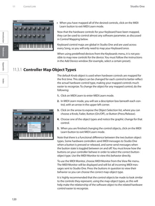
![121
Reference Manual
IntroductionReferenceAppendixIndex
11.4 Control Linking
With an Keyboard set up, and its control map created, you are one click
away from controlling almost any software parameter using Control Link.
The following describes the various ways to use Control Link.
11.4.1 Parameter Windows
To the far left of the Arrange view toolbar in the Song window, you will
notice two windows separated by a button. The windows are empty by
default. The name, value, and other related information regarding the
last-changed software parameter are displayed in the left window. The
MIDI name and value of the last-changed, mapped hardware control are
displayed in the right window.
You also can open Parameter windows in each plug-in window. To do
this, click on the Edit Mapping button at the top of the plug-in window.
11.4.2 Link a Hardware Control to a Software Control
The fastest way to link a hardware and software control is:
Manipulate the desired software control with the mouse.1.
Manipulate the desired hardware control; for instance, turn a knob.2.
That control should appear in the right parameter window.
Click on the3. Link button in the middle of the two parameter windows,
or press [Alt]/[Option]+[M] on the keyboard, and the button should
turn blue.
Your hardware control is now linked to the software control, so that4.
manipulating the hardware control will in turn manipulate the linked
software control.
A second way to link a hardware and software control is:
Open the control map for the desired Keyboard by double-clicking on1.
it in the External panel of the Console.
Manipulate the desired software control with the mouse.2.
Click on the Hand icon in the left parameter window and drag it over3.
the desired hardware control in the control map, then release the
mouse button.
Your hardware control is now linked to the software control, so that4.
manipulating the hardware control will in turn manipulate the linked
software control.
Contol Link 11](https://image.slidesharecdn.com/4cee09e1-25e7-4441-8b08-e26836a7f5f4-160215210245/85/Music-Computing-StudioBLADE-Gen-3-Manual-Full-206-320.jpg)
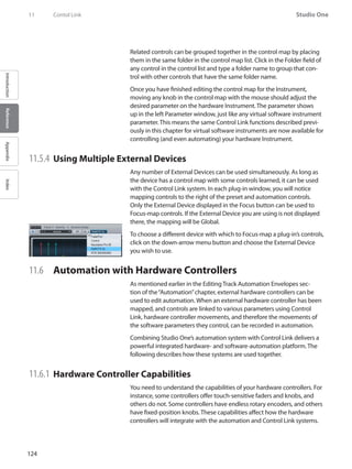
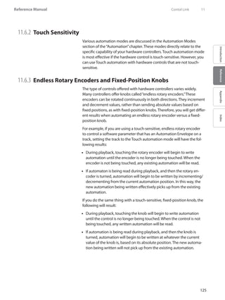
![126
Studio One
IntroductionReferenceAppendixIndex
11 Contol Link
11.6.4 Writing Track Automation
There are three Track Automation modes in which automation can be
written using external controls, including Write, Touch, and Latch. It is rec-
ommended you be familiar with these modes, as described in the Track
Automation Modes section of the“Automation”chapter.
To write Track Automation using an external control, first link a control to
a software parameter, as described in the Control Linking section of this
chapter. Then, show automation by pressing [A] on the keyboard, add an
Automation Envelope to a track for the desired parameter, and enable
Touch, Latch, or Write mode. Finally, start playback and manipulate the
hardware control to write the desired automation.
Automation can be written using hardware controls only during play-
back.
When overwriting existing automation, note that the three automation
modes will give different results.
•• Touch mode will allow automation to be read until a touch-sensitive
control is manipulated, and it will be read again when the control is no
longer being manipulated.
Latch mode will result in automation being read until a control, touch-••
sensitive or not, is manipulated, after which automation will continue
being written until playback is stopped.
When in•• Write mode, no existing automation will be read during play-
back, and automation is written for the duration of playback.
Track Automation cannot be written using an external control if Read or
Off mode is selected on the track.
11.6.5 Writing Instrument Part Automation
Using external controls with Part Automation is similar to using them
with Track Automation, except that there are no automation modes. Exist-
ing Part Automation is read and can be overwritten, and new automa-
tion can be written at all times while recording to a Part, as explained in
the Recording Part Automation section of the“Automation”chapter. The
concept is that Part Automation is an integral part of the Instrument Part
itself and should therefore be used and accessible at all times.](https://image.slidesharecdn.com/4cee09e1-25e7-4441-8b08-e26836a7f5f4-160215210245/85/Music-Computing-StudioBLADE-Gen-3-Manual-Full-211-320.jpg)
![127
Reference Manual
IntroductionReferenceAppendixIndex
12 Mastering (Studio One Pro)
Mastering is the process of preparing and transferring the final mix to
a master copy from which all distribution copies will be made. In the
mastering process, the source material is usually processed using equal-
ization, compression, and so on. Editing, level adjustments, fades, noise
reduction, and other signal restoration and enhancement may also be
done during mastering. Individual songs are put into their final order at
this stage, a process commonly called assembly or track sequencing. The
mastered material is then ready for CD/DVD replication, vinyl pressing, or
Web distribution.
Studio One Pro features the Project page, a complete mastering solution
that is integrated into Studio One. Before Studio One, users had to rely on
at least two separate applications—one for multitrack audio production
and the other for mastering—to complete their audio production. This
can be very inefficient for the average musician/producer.
The Studio One Pro Project page redefines this process into one that is
smart, simple, and efficient. In the Project page, your Songs can be mas-
tered and arranged on a single timeline, and then published to many pro-
fessional formats. The following chapter describes the mastering process,
Project workflow, and how Songs and Projects are integrated to provide a
total solution not available in any other DAW.
Many of the capabilities of the Song page are available in the Project
page, such as Control Link. As such, you should become familiar with the
Song page. The following describes in detail only the workflow specific to
the Project page.
12.1 Creating a New Project
To create a new mastering Project, do one of the following.
Select•• Create a New Project from the Start page.
Navigate to File/New•• Project.
Press [Ctrl]/[Cmd]+[Shift]+N on the keyboard.••
From the•• Song page, click on the Project quick-access button if no Proj-
ect is currently open.
Mastering 12](https://image.slidesharecdn.com/4cee09e1-25e7-4441-8b08-e26836a7f5f4-160215210245/85/Music-Computing-StudioBLADE-Gen-3-Manual-Full-212-320.jpg)
![128
Studio One
IntroductionReferenceAppendixIndex
12 Mastering
12.1.1 Project Setup
In the New Project menu, you can specify a Project Title and save a
location, as well the Project sample rate. Click on OK to create the New
Project.
12.2 Adding Tracks
The first step in the mastering process is to place the desired source ma-
terial into a Project.
12.2.1 The Browser
Just as on the Song page, the Project page has an integrated Browser, al-
lowing you to browse for Audio Effects and files to add to your mastering
Project. Press [F5] on the keyboard, or click on Browse in the lower right
hand corner of the Project page interface, to open the Browser.
12.2.2 Add a Song
Any Song created in Studio One Pro can be added directly to a Project by
importing the Song file itself into the Project.There is no need to create a
mix-down of the Song first, as this process is automated in Studio One Pro.
By default, your Song files are contained in the Content/Songs folder of
the File Browser, with each Song file contained in its own Song folder. To](https://image.slidesharecdn.com/4cee09e1-25e7-4441-8b08-e26836a7f5f4-160215210245/85/Music-Computing-StudioBLADE-Gen-3-Manual-Full-213-320.jpg)
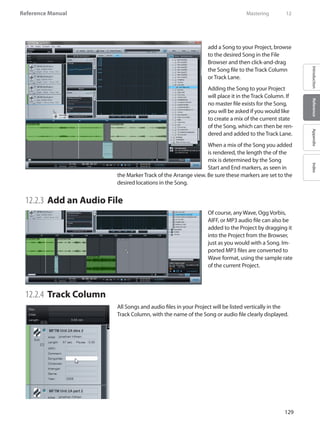
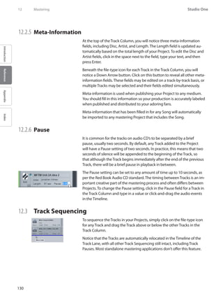
![131
Reference Manual
IntroductionReferenceAppendixIndex
12.3.1 Track Lane and Timeline
The Track Lane is where your Tracks are represented as Audio Events.You
will notice that the Tracks are staggered in the Track Lane, alternating
between an upper and lower position across the Timeline. This allows
two adjacent Tracks to overlap if so desired. By default, the Tracks will be
separated by an amount of time dependent on the Pause setting for each
Track.
To move any Track manually across the Timeline, click-and-drag the Track
left or right. Notice that the sequencing of all other Tracks in the Project is
maintained when any Track is moved across the Timeline.
12.4 Editing Tracks
12.4.1 Sizing Tracks
Tracks in the Track Lane can be sized with the Arrow Tool, as described in
the Size an Event section of the“Editing”chapter. The relative sequencing
of all other Tracks in the Project is maintained when any Track is sized.
12.4.2 Volume Envelope Editing
Each Track in the Track Lane features a volume envelope, which can be
edited like the volume envelopes of Audio Events, as described in the
Adjust Audio Event Volume Envelopes section of the“Editing”chapter. A
volume envelope lets you create fade-ins and fade-outs.
12.4.3 Crossfading Overlapping Tracks
When a Track is manually moved across the Timeline so that it overlaps in
time with another Track, it is possible to crossfade the two Tracks so that
one will fade out as the other fades in. To crossfade overlapping Tracks,
select the two tracks and press [X] on the keyboard. A linear crossfade
will be drawn that can be edited by clicking-and-dragging on each track’s
fade handle.
Any Track that begins after another Track in time will naturally be the
beginning of a new track on a CD or other medium, with the starting
position of that Track serving as the beginning of the track, regardless of
the timing of crossfades.
Mastering 12](https://image.slidesharecdn.com/4cee09e1-25e7-4441-8b08-e26836a7f5f4-160215210245/85/Music-Computing-StudioBLADE-Gen-3-Manual-Full-216-320.jpg)
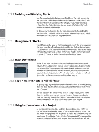
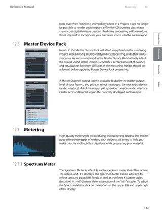
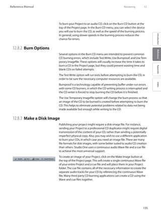
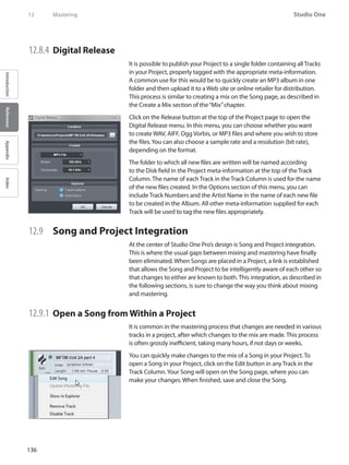
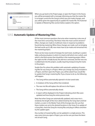
![138
Studio One
IntroductionReferenceAppendixIndex
12 Mastering
When a mastering file in a Project is not up to date, a red light will appear
to the left of the track name in the Track Column, as well as in the lower
left corner of the track in the Track Lane.You can choose to manually
update any of these files by [Right]/[Control]-clicking on the Track and
selecting Update Mastering File. When the file is up to date, a green light
will appear.
You can also update every mastering file in the Project at once by clicking
on the Update button at the top of the Project page. Any files that need
to be updated, based on whether saved changes have occurred to the
Songs, will be updated in the same process described above.
12.9.3 Add Currently Open Song to a Project
To add a Song you are currently working on to a new or open Project, se-
lect Add to Project from the Song file menu. Select any open Project from
the list or select New Project. This will add the Song file to the desired
Project and will automatically render a mixdown that will be placed in the
Project timeline.
12.9.4 Update a Mastering File from the Song Page
To update a mastering file for the currently open Song from within the
Song page, select Update Mastering File from the Song file menu. This
will update the mastering file for the Song, which can exist in any number
of Projects. The next time any Project that contains the Song is opened,
the new mastering file will appear automatically for that Song.](https://image.slidesharecdn.com/4cee09e1-25e7-4441-8b08-e26836a7f5f4-160215210245/85/Music-Computing-StudioBLADE-Gen-3-Manual-Full-223-320.jpg)
![139
Reference Manual
IntroductionReferenceAppendixIndex
13 Built-In Effects
Studio One features a number of high-quality, 64-bit, built-in audio ef-
fects and virtual instruments. The following chapter describes each audio
effect in detail. Virtual instruments will be covered in a separate chapter.
13.1 Built-In Effect Micro Views
All of the built-in effects feature Micro Views, which are small, expand-
able control panels within the Insert Device Rack that allow control over
the critical parameters of each effect. Using the Micro View in the Insert
Device Rack will often prevent having to open the entire effect interface,
and it also allows easy monitoring of compression, gating, and other
effects. Try the built-in effects Micro Views in both the small and large
Console views.
To expand the Micro View for any built-in effect, open the Console and
click once on the effect in the Insert Device Rack. The Micro View will
expand downward, revealing certain parameters of the effect. Not all
parameters of each effect are available in the Micro View, only those you
are likely to change frequently.
In the large Console example, notice the arrows at the very top and
bottom of the Insert Device Rack. Click on these arrows to scroll up and
down in the Insert Device Rack to view any number of open Micro Views.
To collapse any Micro View, click once on the effect name at the top of
the Micro View.
13.2 Built-In Effect Metering Options
All of the built-in effects that feature Peak/RMS meters can optionally
meter using K-System metering, as discussed in the“Mixing”chapter. To
view and select a K-System metering option, [Right]/[Control]-click on the
Peak/RMS meter of the effect.
13.3 Analysis
Visually keeping track of various elements of audio playback while mixing
and mastering can be very helpful when making critical production deci-
sions. The following audio effects are excellent tools for visually monitor-
ing your audio.
Built-In Effects 13](https://image.slidesharecdn.com/4cee09e1-25e7-4441-8b08-e26836a7f5f4-160215210245/85/Music-Computing-StudioBLADE-Gen-3-Manual-Full-224-320.jpg)
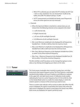
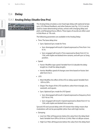
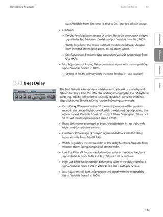
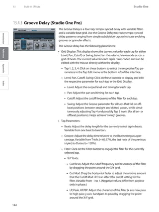
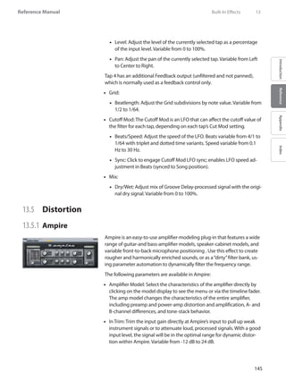
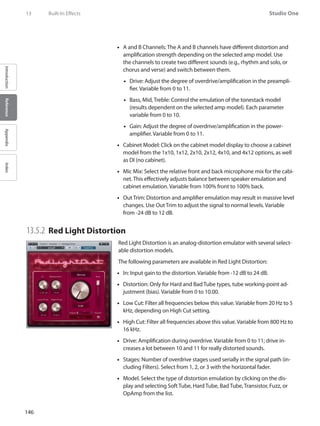
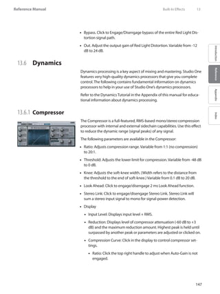
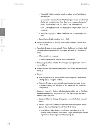
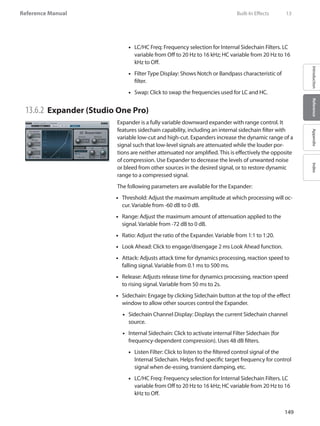
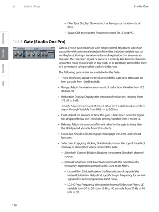
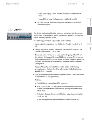
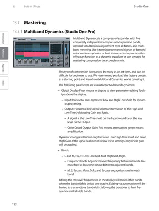
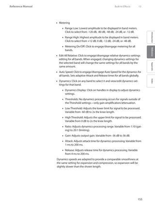
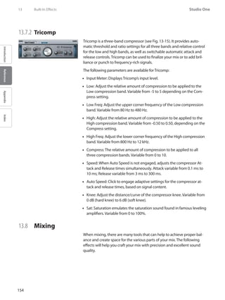
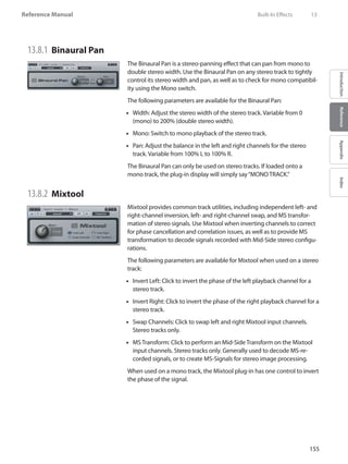
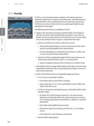
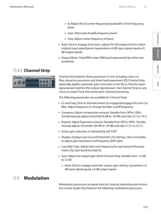
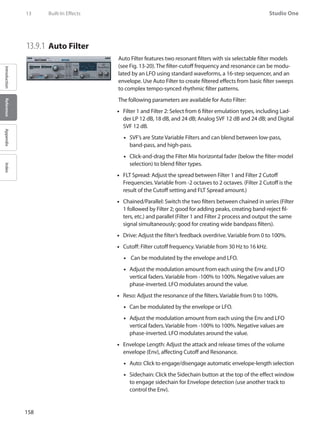
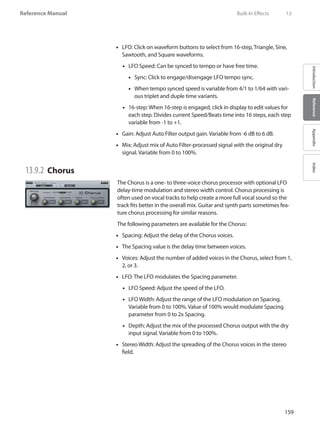
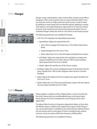
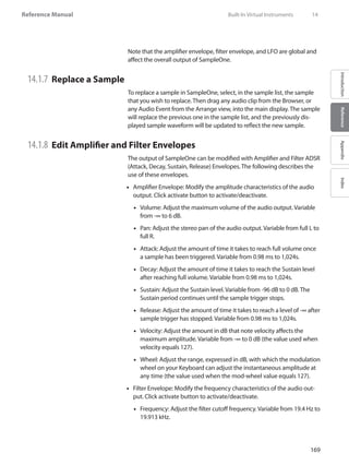
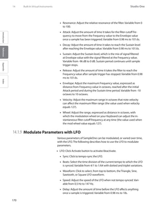
![171
Reference Manual
IntroductionReferenceAppendixIndex
Vibrato: Adjust the range within which the LFO will affect sample••
pitch. Variable from -200 cents (start at -200 cents, range from -200
to +200) to 200 cents (start at +200 cents, range from +200 to -200).
Filter: Adjust the frequency range, expressed as distance in octaves,••
within which the LFO will affect the instantaneous cutoff-frequency
value of the Filter. Variable from -6.7 oct to 6.7 oct.
Amplifier: Adjust the peak amplitude amount with which the LFO••
will modulate the instantaneous amplitude. Variable from -∞ to 0 dB.
Wheel: Adjust the peak amplitude amount with which the modula-••
tion wheel will control the LFO signal strength (LFO strength when
mod wheel value equals 127). Variable from -∞ to 0 dB.
14.2 Impact
Impact features a grid of pads into which samples are loaded and played
back independently, as with many popular hardware drum-sample play-
ers. Each pad has its own pitch, amplifier, and filter controls with accom-
panying envelopes. There are multiple stereo and mono outputs for each
pad, making sophisticated output busing simple.
14.2.1 Interface
Impact is arranged as a 4x4 grid of pads, with controls for each pad.
Below each pad are Solo and Mute controls, as well as an output-channel
assignment. Click on any pad to select it and view its parameters, located
on the right side of the interface. Below the pad parameters are Add and
Remove buttons for adding or removing a sample from the currently
selected pad, as well as Group controls for grouping pads.
14.2.2 Add and Play a Sample
To add a sample to a pad, drag any audio clip from the Browser, or any
Audio Event from the Arrange view, directly onto the desired pad. Each
pad can contain only one sample. Dragging a sample to a pad that al-
ready contains a sample will replace the old sample with the new one. To
remove any sample, [Right]/[Control]-click on the desired pad and select
Remove Clip.
Once a sample has been added to a pad, you can trigger the sample by
clicking on the pad with the mouse, or by playing that pad’s assigned
note on your Keyboard. The note assignment is displayed in the upper
left corner of each pad. To solo a pad, so that no other pad will play when
Built-In Virtual Instruments 14](https://image.slidesharecdn.com/4cee09e1-25e7-4441-8b08-e26836a7f5f4-160215210245/85/Music-Computing-StudioBLADE-Gen-3-Manual-Full-256-320.jpg)
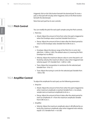
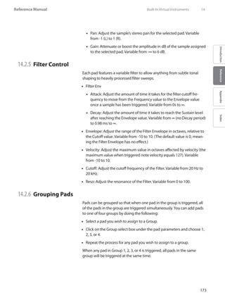
![174
Studio One
IntroductionReferenceAppendixIndex
14.2.7 Using Multiple Outputs
Impact features two stereo outputs and three different mono outputs for
each pad. To change the output routing, do the following:
Click on the Channels button at the top of the•• Impact window to open
the output-channel’s Activation menu.
Click on the checkbox next to any output you wish to use. These chan-••
nels will then appear in the Mix Console.
Click on the Output selection box below the desired pads and choose••
the desired output channel for each pad.
14.3 Presence
Presence is a virtual sample-player instrument that enables
you to play an enormous variety of sounds. Presence uses
a native sound format packaged into Sound Sets, and can
also load and play any SoundFont. The Sound Sets include
a wide variety of instruments, such as pianos, strings,
horns, and percussion. These sounds can be extensively
shaped using the built-in Filter and Amplifier Envelopes
and Modulation LFO.
14.3.1 Load and Play a Preset
The Sound Sets included with Studio One can be found as presets in Pres-
ence. To browse the presets, click on the Preset window. Click once on any
preset in the list to load the preset in Presence. When loaded, the preset
is immediately playable by clicking on the keyboard display or by using
your Keyboard.
14.3.2 Add SoundFonts to Your Library
In order to be accessed directly in Presence, SoundFonts must be added
to the Studio One Instrument Library, found in File/Options/Locations/In-
strument Library [Mac OS X: Preferences/ Options/Locations/Instrument
Library]. To make your SoundFonts directly accessible in Presence, simple
add the storage location in which they reside to the Instrument Library.
To do this, click on Add in the Instrument Library menu, browse to the
appropriate location, and click OK. SoundFonts found in the specified
location will be added to the preset list in Presence.
14 Built-In Virtual Instruments](https://image.slidesharecdn.com/4cee09e1-25e7-4441-8b08-e26836a7f5f4-160215210245/85/Music-Computing-StudioBLADE-Gen-3-Manual-Full-259-320.jpg)
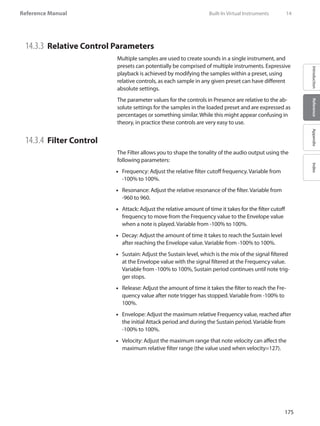
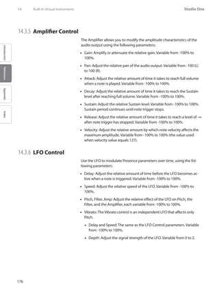
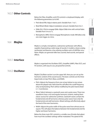
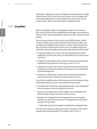
![184
Studio One
IntroductionReferenceAppendixIndex
SelectRangeTool 2
SelectSplitTool 3
SelectEraserTool 4
SelectPaintTool 5
Automation
Action KeyCommand
ShowAutomation A
Show/EditCurrentParameter Alt+A
MapCurrentParametertotouchedControl Alt+M
AutomationRead J
AutomationTouch K
Mixer
Action KeyCommand
ToggleSize Shift+F3
ToggleDetach Cmd+F3
NextChannel ]
PreviousChannel [
NextBank }
PreviousBank {
GlobalSolo Cmd+Shift+S
GlobalMute Cmd+Shift+M
Help
Action KeyCommand
StudioContextHelp F1
StudioContentsHelp Alt-F1
StudioKeyCommands Alt-F2
Special Modifier Keys
CommandinArrangementswitchestoRangeToolwhenusingtheSelectTool.
Commandwhiledraggingaudioeventsorinstrumentpartscreatescopy.
Altwhiledragginginstrumentpartdragcreatesghostcopy.
Altwhileresizingaudioeventstretchesevent.
Command+Altwhiledraggingslipsaudioevents.
Shift+ClickandDragonControlsusesfinetune.
Command+ClickonControlsswitchestothedefaultvalue.
Alt+ClickandDragonMixerlooseschannelfromGroup.
Command+ClickandDragonTrackControlduplicatestrack.
Alt+ClickandDragonTrackControlduplicatestrackwithdata.
Mousewheelinarrangement/editorscrollsvertically.
Shift+Mousewheelinarrangement/editorscrollshorizontally.
Command+Mousewheelinarrangement/editorzoomsvertically.
Table1 Key Commands](https://image.slidesharecdn.com/4cee09e1-25e7-4441-8b08-e26836a7f5f4-160215210245/85/Music-Computing-StudioBLADE-Gen-3-Manual-Full-269-320.jpg)
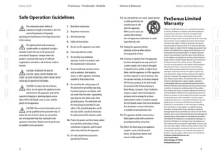
![OverviewGetting
Started
Controlsand
Connections
Cascading
Units
Technical
Information
2 GETTING STARTED PreSonus™ FireStudio™ Mobile
10
OverviewGetting
Started
Controlsand
Connections
Cascading
Units
Technical
Information
GETTING STARTED 2Owner’s Manual
11
OverviewGetting
Started
Controlsand
Connections
Cascading
Units
Technical
Information
2.1 Hardware Installation Hardware Installation 2.1
GETTING STARTED
2.1 Hardware Installation
The Universal Control and included driver can
be used for any interface in the FireStudio family
(FireStudio [26x26], FireStudio Lightpipe, FireStudio
Tube, FireStudio Project, FireStudio Mobile, and
StudioLive 16.4.2). For more information on the
Universal Control application and multiple interface
integration, please review Sections 3.1 and 4.1.
2.1.1 Installation in MicrosoftWindows
After you install the Universal Control CD in your CD
or DVD drive, the Universal Control installer will take
you through each step of the installation process.
Please read each message carefully, ensuring
especially that you do not connect your FireStudio
Mobile until the installer has finished and you have
rebooted your computer.
The FireStudio Mobile Installer was designed to be
as simple and easy-to-follow as possible. Please read
each message carefully to ensure that the FireStudio
Mobile driver is properly installed.
Before continuing the FireStudio Mobile Installation
Setup, please close all applications and disconnect
your FireStudio Mobile from your computer. If you
see any Windows Security alerts, click“Install this
driver software anyway”(Vista) or“Continue anyway”
(XP).
At the end of the installation, you will be prompted
to reboot your computer to complete the
installation. Click“Finish”to automatically restart your
PC. Once your computer has rebooted, connect the
FireStudio Mobile. When the Found New Hardware
wizard launches, follow the recommended steps.
When the sync light remains solid blue, your
FireStudio Mobile is synced to your computer and
is ready to use!
2.1.2 Installation in Mac OS X
After inserting the installation CD into your disc
drive, browse the disc and run the FireStudio
Mobile installer, which will take you through each
step of the installation process. Please read each
message carefully, ensuring especially that you
do not connect your FireStudio Mobile until the
installer has finished and you have rebooted your
computer.
To begin installing the FireStudio Mobile driver
on your Mac, double click on the FireStudio
Mobile logo. The FireStudio Mobile installer
requires that your user password be entered as
a security measure. Once you have entered your
password, click“OK”to proceed with the rest of the
installation.
When the Installer has finished, connect your
FireStudio Mobile to your computer with a FireWire
cable. Once the sync light is solid blue, your
FireStudio Mobile is ready to use.](https://image.slidesharecdn.com/4cee09e1-25e7-4441-8b08-e26836a7f5f4-160215210245/85/Music-Computing-StudioBLADE-Gen-3-Manual-Full-280-320.jpg)