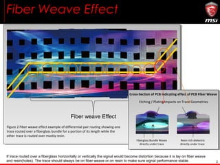
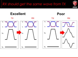
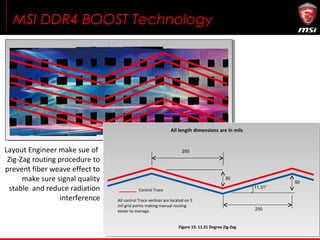
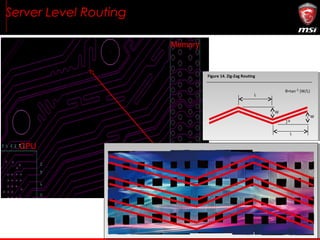
MSI DDR4 Boost
Technology Info
2
Fiber Weave Effect
If trace routed over a fiberglass horizontally or vertically the signal would become distortion because it is lay on fiber weave
and resin(holes). The trace should always be on fiber weave or on resin to make sure signal performance stable.
Fiber weave Effect
Figure 2 Fiber weave effect example of differential pair routing showing one
trace routed over a fiberglass bundle for a portion of its length while the
other trace is routed over mostly resin.
Cross-Section of PCB indicating effect of PCB Fiber Weave
Etching / Plating impacts on Trace Geometries
Fiberglass Bundle Waves
directly under trace
Resin rich dielectric
directly under trace
RX should get the same wave from TX
TX TXRX RX
Excellent Poor
MSI DDR4 BOOST Technology
Layout Engineer make sue of
Zig-Zag routing procedure to
prevent fiber weave effect to
make sure signal quality
stable and reduce radiation
interference
Figure 15: 11.31 Degree Zig-Zag
All length dimensions are in mils
All control Trace vertices are located on 5
mil grid points making manual routing
easier to manage.
Control Trace
250
50
250
11.31°
50
Server Level Routing
Figure 14. Zig-Zag Routing
L
W
L
W
θ=tan (W/L)-1
θ
CPU
Memory
Moat: just like wall to prevent outer noise interference
What Our
Memory Partners
Say…
Thank You Very Much for Your Attention

MSI DDR4 Boost

  • 1.
  • 2.
    2 Fiber Weave Effect Iftrace routed over a fiberglass horizontally or vertically the signal would become distortion because it is lay on fiber weave and resin(holes). The trace should always be on fiber weave or on resin to make sure signal performance stable. Fiber weave Effect Figure 2 Fiber weave effect example of differential pair routing showing one trace routed over a fiberglass bundle for a portion of its length while the other trace is routed over mostly resin. Cross-Section of PCB indicating effect of PCB Fiber Weave Etching / Plating impacts on Trace Geometries Fiberglass Bundle Waves directly under trace Resin rich dielectric directly under trace
  • 3.
    RX should getthe same wave from TX TX TXRX RX Excellent Poor
  • 4.
    MSI DDR4 BOOSTTechnology Layout Engineer make sue of Zig-Zag routing procedure to prevent fiber weave effect to make sure signal quality stable and reduce radiation interference Figure 15: 11.31 Degree Zig-Zag All length dimensions are in mils All control Trace vertices are located on 5 mil grid points making manual routing easier to manage. Control Trace 250 50 250 11.31° 50
  • 5.
    Server Level Routing Figure14. Zig-Zag Routing L W L W θ=tan (W/L)-1 θ CPU Memory
  • 6.
    Moat: just likewall to prevent outer noise interference
  • 7.
  • 12.
    Thank You VeryMuch for Your Attention