Modelling And Control Of Miniflying Machines Advances In Industrial Control 1st Edition Pedro Castillo
Modelling And Control Of Miniflying Machines Advances In Industrial Control 1st Edition Pedro Castillo
Modelling And Control Of Miniflying Machines Advances In Industrial Control 1st Edition Pedro Castillo

![1
Introduction and Historical Background
Automatic flying of intelligent vehicles moving in space represents a huge
field of applications. We are particularly interested in this book in small vehi-
cles, such as helicopters in all configurations (configuration with a main rotor
with or without tail rotor, configuration in tandem, configuration with coaxial
opposite rotary rotors, configuration with four, two or one rotors) for their
adaptability and manoeuvrability. Helicopters are relatively complex and dif-
ficult to control but they allow to carry out various tasks. Automating these
machines allows among other things to guarantee a minimum of security when
the pilot is no longer able to control the vehicle. Automatic flying can also
be used when the task to be achieved is too repetitive or too difficult for the
pilot [122].
Automatic control of small flying machines opens up applications in the
fields of security (supervision of aerial space, urban traffic), management
of natural risks (supervision of active volcanoes), of environment (measur-
ing air pollution, supervision of forests), for intervention in hostile environ-
ments (radioactive atmospheres, removal of mines without human interven-
tion), management of ground installations (dams, lines with high tension,
pipelines), agriculture (detection and treatment of infested cultivations), and
aerial shooting in the production of movies, to cite a few examples [114, 157].
In this chapter we briefly present the evolution of flying machines that are
able to take-off vertically. A historical review is given for various multi-rotor
rotorcraft as well as some definitions.](https://image.slidesharecdn.com/1082115-250606011935-01a0a834/75/Modelling-And-Control-Of-Miniflying-Machines-Advances-In-Industrial-Control-1st-Edition-Pedro-Castillo-20-2048.jpg)
![2 1 Introduction and Historical Background
1.1 Definitions
Aircraft
An aircraft is any machine capable of flight. Aircraft can be divided into two
categories [185]:
• Heavier: Autogyros, helicopters and variants, and conventional fixed-wing
aircraft.
• Lighter: Balloons and airships. The distinction between a balloon and an
airship is that an airship has some means of controlling forward motion
and steering while balloons simply drift with the wind.
The abbreviation VTOL is applied to aircraft other than helicopters that
can take-off or land vertically. Similarly, STOL stands for Short Take Off and
Landing.
Fig. 1.1. Components of a helicopter.
Helicopter
A helicopter is an aircraft that can take-off and land vertically. Also called
a rotary aircraft, this aircraft can hover and rotate in the air and can move
sideways and backwards while aloft. This aerial vehicle can change direction
very quickly and can stop moving completely and begin hovering [116].
The helicopter began as a basic principle of rotary-wing aviation. The
precision of parts due to the Industrial Revolution enabled the helicopter to
evolve into the modern machines we see flying today. The need for accurate
machinery and fixtures was evident when the earliest helicopter models lacked
the efficiency and flying capability of modern helicopters. The main compo-
nents of a helicopter are given in Figure 1.1.](https://image.slidesharecdn.com/1082115-250606011935-01a0a834/75/Modelling-And-Control-Of-Miniflying-Machines-Advances-In-Industrial-Control-1st-Edition-Pedro-Castillo-21-2048.jpg)
![1.2 Early Concepts of VTOL Aircraft 3
UAV
An Unmanned Aerial Vehicle (UAV), also called a drone, is a self-descriptive
term used to describe military and civil applications of the latest generations
of pilotless aircraft [185]. UAVs are defined as aircraft without the onboard
presence of pilots [179], used to perform intelligence, surveillance, and re-
connaissance missions. The technological promise of UAVs is to serve across
the full range of missions. UAVs have several basic advantages over manned
systems including increased manoeuvrability, reduced cost, reduced radar sig-
natures, longer endurance, and less risk to crews.
1.2 Early Concepts of VTOL Aircraft
“The idea of a vehicle that could lift itself vertically from the ground and
hover motionless in the air was probably born at the same time that man first
dreamed of flying.”1
During the past sixty years since their first successful flights, helicopters
have matured from unstable, vibrating contraptions that could barely lift the
pilot off the ground, into sophisticated machines of quite extraordinary flying
capability.
The idea of vertical flight aircraft can be traced back to early Chinese
tops, a toy first used about 400 BC. The earliest versions of the Chinese top
consisted of feathers at the end of a stick, which was rapidly spun between
the hands to generate lift and then released into free flight (see Figure 1.2).
These toys were probably inspired by observations of the seeds of trees such
as the sycamore, whose whirling, autorotating seeds can be seen to carry on
the breeze [47, 61, 64].
Fig. 1.2. The first concept of rotary-wing aviation.
1
Igor Ivanovitch Sikorsky](https://image.slidesharecdn.com/1082115-250606011935-01a0a834/75/Modelling-And-Control-Of-Miniflying-Machines-Advances-In-Industrial-Control-1st-Edition-Pedro-Castillo-22-2048.jpg)
![4 1 Introduction and Historical Background
“Trovo, se questo strumento a vite sar ben fatto, cio fatto di tela lina,
stopata i suoi pori con amido, e svoltata con prestezza, che detta vite si fa la
femmina nellaria e monter in alto.”2
“I believe that if this screw device is
well manufactured, that is, if it is made of linen cloth, the pores of which have
been closed with starch, and if the device is promptly reversed, the screw will
engage its gear when in the air and it will rise up on high” [120].
In 1483 Leonardo Da Vinci designed a sophisticated aircraft capable of
hovering. Some experts have identified this aircraft as the ancestor of the
helicopter. The aircraft called aerial screw or air gyroscope had a diameter of
5 m (see Figure 1.3), and was operated presumably by four men who might
have stood on the central platform and exerted pressure on the bars in front
of them with their hands, so as to make the shaft turn.
The main idea was that if an adequate driving force were applied, the
machine might have spun in the air and risen off the ground.
Fig. 1.3. The air screw. Credits – Hiller Aviation Museum [66].
In 1754, Mikhail Lomonosov developed a small coaxial rotor similar to the
Chinese top but powered by a wound-up spring device. The aircraft flew freely
and climbed to a good altitude [61, 64].
In 1783, Launoy and Bienvenu used a coaxial version of the Chinese top
in a model consisting of a counter-rotating set of turkey feathers [61, 64].
2
Leonardo Da Vinci](https://image.slidesharecdn.com/1082115-250606011935-01a0a834/75/Modelling-And-Control-Of-Miniflying-Machines-Advances-In-Industrial-Control-1st-Edition-Pedro-Castillo-23-2048.jpg)
![1.2 Early Concepts of VTOL Aircraft 5
A large number of minor inventions contributed to the advancement of
the helicopter. Between the fifteenth and twentieth centuries, it was not yet
possible to produce the machinery needed to build helicopters, like turbine
engines and rotors, but as the Industrial Revolution created factories and
technology accelerated, the helicopter evolved.
One of the first breakthroughs in helicopter advancement was by George
Cayley who produced a converti-plane in 1843 [146]. Cayley designed an air-
craft capable of hovering that he called the “aerial carriage” (see Figure 1.4).
However, Cayley’s device remained an idea because the only powerplants avail-
able at the time were steam engines, and these were much too heavy to allow
for successful powered flight [61, 64].
Fig. 1.4. Aerial carriage. Credits – Hiller Aviation Museum [66].
The lack of a suitable powerplant continued to stifle aeronautical progress,
both for fixed and rotating wing applications, but the use of miniature
lightweight steam engines met with some limited success.
In the 1840s, Horatio Phillips constructed a steam-driven vertical flight
machine where steam generated by a miniature boiler was ejected out of the
blade tips [61, 64].
In the 1860s, Ponton d’Amecourt flew a number of small steam-powered
helicopter models (Figure 1.5). He called his machines helicopteres, which is a
word derived from the Greek adjective elikoeioas meaning spiral or winding,
and the noun pteron meaning feather or wing [61, 64].](https://image.slidesharecdn.com/1082115-250606011935-01a0a834/75/Modelling-And-Control-Of-Miniflying-Machines-Advances-In-Industrial-Control-1st-Edition-Pedro-Castillo-24-2048.jpg)
![6 1 Introduction and Historical Background
Fig. 1.5. Gustave Ponton d’Amecourt’s helicopters. Credits – Hiller Aviation Mu-
seum [66].
At the beginning of the twentieth century nearly all prior attempts at
vertical flight could be considered as inventive, the inherent aerodynamic and
mechanical complexities of building a vertical flight aircraft were to challenge
many ambitious efforts. A contributing factor was the relatively few scientific
investigations of flight or studies into the science of aerodynamics. The history
of flight documents literally hundreds of failed helicopter inventions, which
either had inadequate installed power or limited control capability, or more
often than not, the machine just vibrated itself to pieces [61].
In the 1880s, Thomas Alva Edison experimented with small helicopter
models in the United States. He tested several rotor configurations driven by
a gun cotton engine, which was an early form of internal combustion engine.
However, a series of explosions deterred further efforts with these engines.
Later, Edison used an electric motor for power, and he was one of the first
to realize from his experiments the need for a large diameter rotor with low
blade area to give good hovering efficiency [61, 64].
While one can draw several parallels in the technical development of the
helicopter when compared with fixed-wing aircraft, the longer and more tu-
multuous gestation of vertical flight aircraft is a result of the greater depth of
knowledge required before all the various aerodynamic and mechanical prob-
lems could be understood and overcome.
By 1920, gasoline powered piston engines with higher power-to-weight ra-
tios were more widely available, and the control problems of achieving success-
ful vertical flight were at the forefront. This era is marked by the development
of a vast number of prototype helicopters throughout the world. Most of these
machines made short hops into the air or flew slowly forward in ground effect.
Many of the early designs were built in Great Britain, France, Germany, Italy,
and the United States, who led the field in several technical areas [61].](https://image.slidesharecdn.com/1082115-250606011935-01a0a834/75/Modelling-And-Control-Of-Miniflying-Machines-Advances-In-Industrial-Control-1st-Edition-Pedro-Castillo-25-2048.jpg)
![1.2 Early Concepts of VTOL Aircraft 7
Fig. 1.6. Paul Cornu’s aircraft. Credits – Pilotfriend [135, 136].
In 1907, Paul Cornu constructed a vertical flight machine that was re-
ported to have carried a human off the ground for the first time (see Figure
1.6). The airframe was very simple, with a rotor at each end. Power was sup-
plied to the rotors by a 22 hp gasoline motor and belt transmission. Each rotor
had two relatively large but low aspect ratio blades set at the periphery of a
large spoked wheel. The rotors rotated in opposite directions to cancel torque
reaction. A primitive means of control was achieved by placing auxiliary wings
in the slipstream below the rotors. The flight lasted only twenty seconds and
acquired an altitude of thirty centimeters but was still a landmark develop-
ment in helicopter evolution. The helicopter had no effective means of control
and was abandoned after a few flights [61, 64, 116].
By 1909, Igor Ivanovitch Sikorsky had built a nonpiloted coaxial helicopter
prototype. This aircraft did not fly because of vibration problems and the lack
of a powerful enough engine. In 1912, Boris Yur’ev tried to build a helicopter
in Russia (Figure 1.7). This machine had a very modern looking single rotor
and tail rotor configuration. The large diameter, high aspect ratio blades sug-
gested some knowledge that this was the configuration for high aerodynamic
efficiency. Yet, besides being one of the first to use a tail rotor design, Yur’ev
was one of the firsts to propose the concepts of cyclic pitch for rotor control.
Fig. 1.7. Boris Yur’ev’s aircraft [64, 148].](https://image.slidesharecdn.com/1082115-250606011935-01a0a834/75/Modelling-And-Control-Of-Miniflying-Machines-Advances-In-Industrial-Control-1st-Edition-Pedro-Castillo-26-2048.jpg)
![8 1 Introduction and Historical Background
During World War I, military interest contributed to the advancement
of the helicopter. Von Karman and Petrosczy, both from Germany, and the
Hungarian Asboth intended to produce, without success, a lifting device to
replace kite balloons for observation consisted of two superimposed lifting
propellers (Figure 1.8).
Fig. 1.8. Petroczy – Von Karman’s helicopter. Credits – Hiller Aviation Museum
[66, 116].
It was not until late in World War I that major helicopter advances were
made. The quality and quantity of production materials increased, and great
improvements were made in the field of engine technology. With better tech-
nology and more need, the next step in helicopter advancement would soon
come.
In 1922, George de Bothezat built a helicopter with four rotors, under the
sponsorship of the U.S. Army (see Figure 1.9). The helicopter had four six-
bladed rotors mounted at the ends of beams 18 m in length, forming a cross
and intersecting in all directions. The rotor axes were not parallel but slightly
inclined inwards so that if extended they would have met at a point directly
above the centre of gravity. Besides the rotors with variable-pitch blades, the
helicopter had two horizontal propellers called steering airscrews as well as
two small airscrews placed above the gearbox and acting as regulators for the
220 hp engine. Ready for flight, the helicopter weighed 1700 kg.
In 1923, Juan de la Cierva developed the autogyro,3
which resembled the
helicopter, but used an unpowered rotor. This aircraft looked a lot like a hybrid
between a fixed-wing airplane and a helicopter, with a set of conventional
wings and a tail but with a rotor mounted on a vertical shaft above the
fuselage (Figure 1.10). The blades were attached to the shaft for cyclic pitch
control to balance the amount of lift and torque caused by the rotating blades
and produce a stable ride. The articulated rotor blade is used today on all
3
An autogyro is an aircraft with an unpowered rotary wing, or rotor, that resembles
a helicopter. It is powered by either an engine-powered propeller or a tow cable.
The movement of air past the rotor causes the lift [185].](https://image.slidesharecdn.com/1082115-250606011935-01a0a834/75/Modelling-And-Control-Of-Miniflying-Machines-Advances-In-Industrial-Control-1st-Edition-Pedro-Castillo-27-2048.jpg)
![1.2 Early Concepts of VTOL Aircraft 9
Fig. 1.9. Bothezat’s helicopter. Credits – National Museum of the United States
Air Force [121].
helicopters. Two Cierva C.40 autogyros were used for Air Observation Post
during World War I. Autogyros could neither hover nor descend vertically like
the modern helicopter.
Fig. 1.10. Cierva’s autogyro. Credits – Hiller Aviation Museum [66, 116].
In 1936, Heinrich Focke and Gert Achgelis built a side-by-side, two-rotor
machine, called the Fa-61 (Figure 1.11). This aerial vehicle was constructed
from the fuselage of a small biplane trainer with rotor components provided
by the Weir-Cierva company. Longitudinal control was achieved by tilting the
rotors forward and aft by means of a swashplate mechanism, while yaw control
was gained by tilting the rotors differentially. The rotors had no variable
collective pitch, instead using a slow and clumsy system of changing rotor
speed to change the rotor thrust. A vertical rudder and horizontal tail provided
for additional directional stability. The cut-down propeller on the front of the
machine served only to cool the radial engine. The Fa-61 vehicle was the first
helicopter to show fully controlled flight and also to demonstrate successful
autorotations [61].](https://image.slidesharecdn.com/1082115-250606011935-01a0a834/75/Modelling-And-Control-Of-Miniflying-Machines-Advances-In-Industrial-Control-1st-Edition-Pedro-Castillo-28-2048.jpg)
![10 1 Introduction and Historical Background
Fig. 1.11. The Fa-61 helicopter. Credits – Pilotfriend [64, 135, 136].
The success in the field of rotary-wing aviation was due almost entirely
to Igor Sikorsky. In 1939, Sikorsky built the first classical helicopter, the VS-
300 (Figure 1.12). This aircraft had one main rotor and three auxiliary tail
rotors, with longitudinal and lateral control being obtained by means of pitch
variations on the two vertically thrusting horizontal tail rotors. Powered only
with a 75 hp engine, the machine could hover, fly sideways and backwards,
and perform many other manoeuvres.
The main rotor of the VS-300 was used in the VS-300A helicopter with
a more powerful engine, but only the vertical (sideward thrusting) tail rotor
was retained out of the original three auxiliary rotors. In this configuration,
longitudinal and lateral control was achieved by tilting the main rotor by
means of cyclic-pitch inputs; the single tail rotor was used for antitorque and
directional control purposes. This configuration was to become the standard
for most modern helicopters.
Fig. 1.12. Sikorsky’s helicopters. Credits – Sikorsky Aircraft Corp. [64, 152].
During the 1950s many new advancements in helicopters were made. Siko-
rsky crafted the world’s first certified commercial transport helicopter, the
S-55 Chickasaw (H-19) (Figure 1.13).](https://image.slidesharecdn.com/1082115-250606011935-01a0a834/75/Modelling-And-Control-Of-Miniflying-Machines-Advances-In-Industrial-Control-1st-Edition-Pedro-Castillo-29-2048.jpg)
![1.2 Early Concepts of VTOL Aircraft 11
Fig. 1.13. The S-55 helicopter. Credits – Enell Postcards [40].
Another well-known pioneer who contributed to the development of the
modern helicopter was Stanley Hiller. In 1944, Hiller built the coaxial heli-
copter. His main breakthrough was the rotormatic main rotor design, where
the cyclic pitch controls were connected to a set of small auxiliary blades set
at ninety degrees to the main rotor blades [61].
The creation of the turbine engine advanced the helicopter’s capabilities
even further. With assembly lines brought about by the Industrial Revolution,
these engines could be produced with high efficiency and increased precision.
At the beginning of the new millennium, the advance in many technologies,
i.e. propulsion, materials, electronics, computers, sensors, navigation instru-
ments, etc., contributed to the development of helicopters and other configu-
rations of aerial vehicles capable of hovering.
The main roles of helicopters range from the civilian to the military. Civil-
ian roles are surveillance, sea and mountain rescue, air ambulance, fire fight-
ing, crop dusting, etc. Military roles include troop transport, mine-sweeping,
battlefield surveillance, assault and anti-tank missions, etc.
Since the 1980s, sustained scientific research has been particularly inter-
ested in understanding the most difficult technical problems associated with
helicopter flight, particularly in regard to aerodynamic limitations imposed
by the main rotor. The improved design of the helicopter and the increasing
viability of other vertical lift aircraft such as the tilt-rotor continue to advance
as a result of the revolution in new technology.
The helicopter today is a safe, versatile, and reliable aircraft, that plays
a unique role in modern aviation. The new generations of aircraft capable
of hovering are designed to be smaller, lighter and with some autonomous
functions.](https://image.slidesharecdn.com/1082115-250606011935-01a0a834/75/Modelling-And-Control-Of-Miniflying-Machines-Advances-In-Industrial-Control-1st-Edition-Pedro-Castillo-30-2048.jpg)
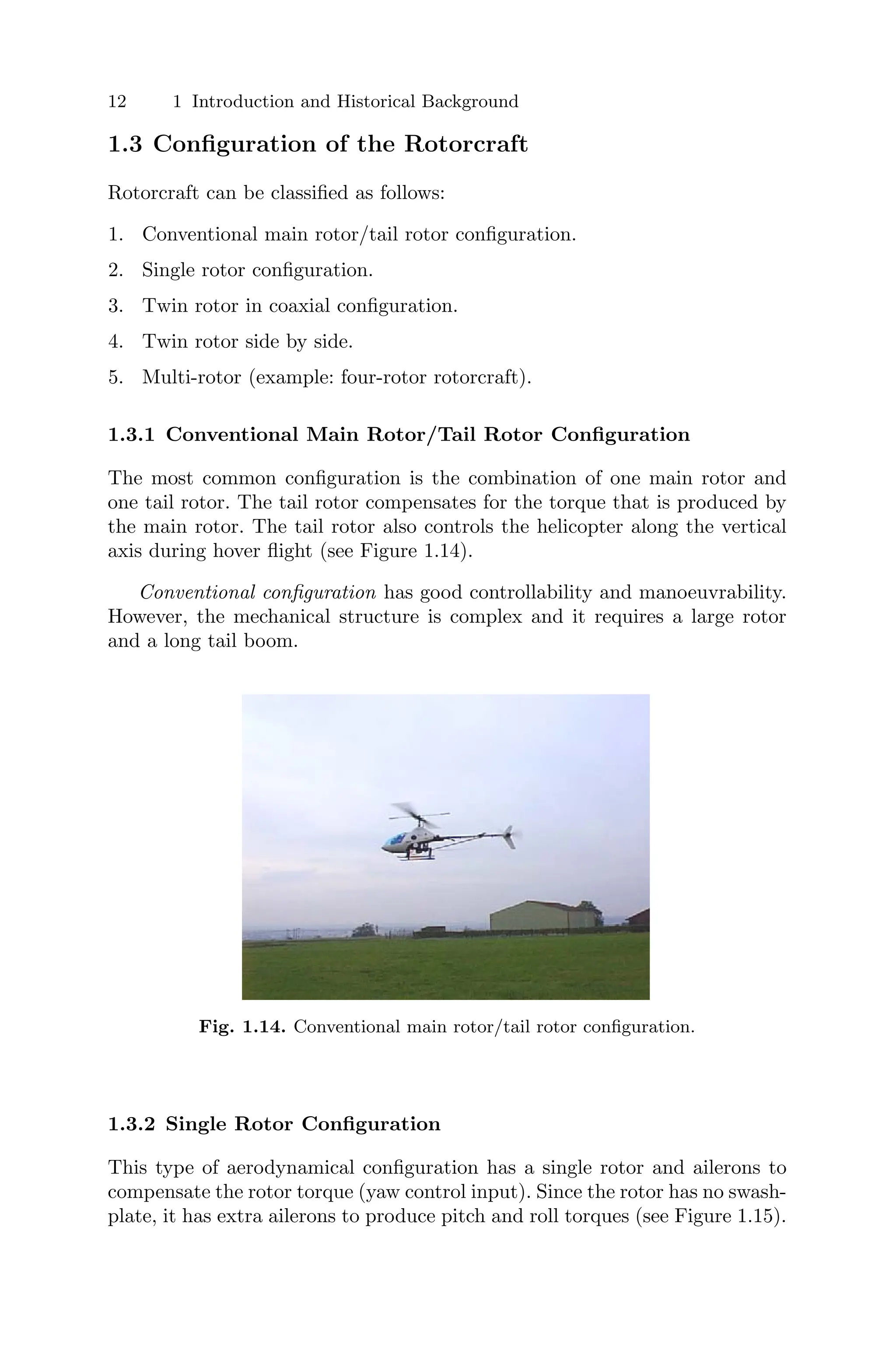
![1.3 Configuration of the Rotorcraft 13
This type of flying machine is in general difficult to control even for experi-
enced pilots.
Single rotor configuration is mechanically simpler than standard heli-
copters but it does not have as much control authority. In both cases a sig-
nificant amount of energy is used in the anti-torque, i.e. to stop the fuselage
turning around the vertical axis. Due to its mechanical simplicity, this config-
uration seems more suitable for micro-aircraft than the other configurations.
Fig. 1.15. Single rotor configuration – Eurosatory 2004. SAGEM, France.
1.3.3 Twin Rotor in Coaxial Configuration
In this configuration, one rotor is located on top of the other (see Figure
1.16). The two rotors turn in opposite directions. Depending on the angular
velocity difference between the two rotors, the helicopter will turn left or
right. Helicopters with this configuration cannot reach a high cruising speed
because the drag is relatively large. Only after the development of the rigid
rotor was it possible to build the two rotors closer together and reduce the
drag considerably [116].
The coaxial configuration has advantages of compactness. However a sig-
nificant amount of energy is lost because the rotors interfere with each other.
The hover efficiency of the twin rotor side by side is higher than that of the
coaxial because there is no interference between the rotors.
1.3.4 Twin Rotor Side by Side
The tandem rotor (or twin rotor side by side) configuration is used mainly in
large helicopters (Figure 1.17). Because of the opposite rotation of the rotors,](https://image.slidesharecdn.com/1082115-250606011935-01a0a834/75/Modelling-And-Control-Of-Miniflying-Machines-Advances-In-Industrial-Control-1st-Edition-Pedro-Castillo-32-2048.jpg)
![14 1 Introduction and Historical Background
Fig. 1.16. Twin rotor in coaxial configuration (AirScoot helicopter). Credits –
AirScooter Corporation [2].
the torque of each single rotor is neutralized. The construction of the control
system is much more complicated compared with a helicopter with a tail rotor.
The arrangement of two rotors side by side was never very popular [116].
Fig. 1.17. Twin rotor side by side (Sea Knight CH-46 aircraft). Credits – National
Museum of Naval Aviation [119].](https://image.slidesharecdn.com/1082115-250606011935-01a0a834/75/Modelling-And-Control-Of-Miniflying-Machines-Advances-In-Industrial-Control-1st-Edition-Pedro-Castillo-33-2048.jpg)
![1.4 New Configurations of UAVs 15
1.3.5 Multi-rotors
The four-rotor rotorcraft or quadrotor is the more popular multi-rotor rotor-
craft (Figure 1.18). This type of rotorcraft attempts to achieve stable hovering
and precise flight by balancing the forces produced by the four rotors.
One of the advantages of using a multi-rotor helicopter is the increased pay-
load capacity. It has more lift therefore heavier weights can be carried. Quad-
rotors are highly manoeuvrable, which enables vertical take-off and landing,
as well as flying into hard to reach areas. Disadvantages are the increased
helicopter weight and increased energy consumption due to the extra motors.
Since it is controlled with rotor-speed changes, it is more suitable to electric
motors, and large helicopter engines which have slow response may not be
satisfactory without a proper gear-box system [5].
The quadrotor is superior from the control authority point of view. Con-
trolled hover and low-speed flight has been successfully demonstrated. How-
ever further improvements are required before demonstrating sustained con-
trolled forward-flight. When internal-combustion engines are used, multiple
rotor configurations have disadvantages over single rotor configurations be-
cause of the complexity of the transmission gear.
Fig. 1.18. Four-rotor rotorcraft (multi-rotor configuration).
1.4 New Configurations of UAVs
The aerodynamical configurations for mini-UAV are rapidly changing. In Fig-
ures 1.19 to 1.36 we present a selection of recent aerial vehicles capable of
hovering [180].](https://image.slidesharecdn.com/1082115-250606011935-01a0a834/75/Modelling-And-Control-Of-Miniflying-Machines-Advances-In-Industrial-Control-1st-Edition-Pedro-Castillo-34-2048.jpg)
![16 1 Introduction and Historical Background
Fig. 1.19. Seagull-Elbit Systems, Israel. Credits – Defense Update [31].
Fig. 1.20. Dragoneye-AeroVironment, Inc., U.S.A. Credits – Defense Update [31].
Fig. 1.21. Skylite-RAFAEL, Israel. Credits – Defense Update [31].
Fig. 1.22. Skylark-Elbit Systems, Israel. Credits – Defense Update [31].](https://image.slidesharecdn.com/1082115-250606011935-01a0a834/75/Modelling-And-Control-Of-Miniflying-Machines-Advances-In-Industrial-Control-1st-Edition-Pedro-Castillo-35-2048.jpg)
![1.4 New Configurations of UAVs 17
Fig. 1.23. Aerosonde aircraft - Aerosonde Robotic Aircraft. Credits – Aerosonde
[1].
Fig. 1.24. Mikado aircraft - EMT, Germany. Credits – Defense Update [31].
Fig. 1.25. X-45 UCAV aircraft – Boeing Corp.](https://image.slidesharecdn.com/1082115-250606011935-01a0a834/75/Modelling-And-Control-Of-Miniflying-Machines-Advances-In-Industrial-Control-1st-Edition-Pedro-Castillo-36-2048.jpg)
![18 1 Introduction and Historical Background
Fig. 1.26. Cypher aircraft. Credits – Sikorsky Aircraft Corp. [152].
Fig. 1.27. Cypher II aircraft. Credits – Sikorsky Aircraft Corp. [152].
Fig. 1.28. Golden Eye aircraft – Aurora Flight Sciences Corp.](https://image.slidesharecdn.com/1082115-250606011935-01a0a834/75/Modelling-And-Control-Of-Miniflying-Machines-Advances-In-Industrial-Control-1st-Edition-Pedro-Castillo-37-2048.jpg)
![1.4 New Configurations of UAVs 19
Fig. 1.29. iSTAR MAV aircraft – Allied Aerospace. Credits – Defense Update [31].
Fig. 1.30. Kestrel aircraft – Honeywell.
Fig. 1.31. X-50 aircraft – Boeing Corp.](https://image.slidesharecdn.com/1082115-250606011935-01a0a834/75/Modelling-And-Control-Of-Miniflying-Machines-Advances-In-Industrial-Control-1st-Edition-Pedro-Castillo-38-2048.jpg)
![20 1 Introduction and Historical Background
Fig. 1.32. Guardian CL-327 aircraft – Bombadier Services Corp.
Fig. 1.33. TAGM65/M80 - Tactical Aerospace Group (TAG). Credits – Defense
Update [31].
Fig. 1.34. T-Wing aircraft. Credits – University of Sydney, Australia [160].](https://image.slidesharecdn.com/1082115-250606011935-01a0a834/75/Modelling-And-Control-Of-Miniflying-Machines-Advances-In-Industrial-Control-1st-Edition-Pedro-Castillo-39-2048.jpg)
![1.4 New Configurations of UAVs 21
Fig. 1.35. Four-rotor rotorcraft. Credits – Draganfly Innovations Inc. [33].
Fig. 1.36. Three-rotor rotorcraft. Credits – Heudiasyc-UTC, France](https://image.slidesharecdn.com/1082115-250606011935-01a0a834/75/Modelling-And-Control-Of-Miniflying-Machines-Advances-In-Industrial-Control-1st-Edition-Pedro-Castillo-40-2048.jpg)
![2
The PVTOL Aircraft
2.1 Introduction
We introduce in this chapter the well-known Planar Vertical Take-Off and
Landing (PVTOL) aircraft problem. The PVTOL represents a challenging
nonlinear systems control problem that is a particular case of what is today
known as “motion control”. The PVTOL is clearly motivated by the need to
stabilize aircraft that are able to take-off vertically such as helicopters and
some special airplanes.
The PVTOL is a mathematical model of a flying object that evolves in a
vertical plane. It has three degrees of freedom (x, y, φ) corresponding to its
position and orientation in the plane. The PVTOL is composed of two inde-
pendent thrusters that produce a force and a moment on the flying machine,
see Figure 2.1. The PVTOL is an underactuated system since it has three de-
grees of freedom and only two inputs [144]. The PVTOL is a very interesting
nonlinear control problem.
Numerous design methods for the flight control of the PVTOL aircraft
model exist in the literature [24, 26, 45, 53, 92, 96]. Indeed, this particular
system is a simplified aircraft model with a minimal number of states and
inputs but retains the main features that must be considered when designing
control laws for a real aircraft. Since, the system possesses special properties
such as, for instance, unstable zero dynamics and signed (thrust) input [63],
several methodologies for controlling such a system have been proposed.
An algorithm to control the PVTOL based on an approximate I-O lin-
earization procedure was proposed in [63]. Their algorithm achieves bounded
tracking and asymptotic stability. A nonlinear small gain theorem was pro-
posed in [173] which can be used to stabilize a PVTOL. The author has proved
the stability of a controller based on nested saturations [172]. The algorithm
is very simple, has bounded control inputs and performs well even if the initial
horizontal displacement error is large.](https://image.slidesharecdn.com/1082115-250606011935-01a0a834/75/Modelling-And-Control-Of-Miniflying-Machines-Advances-In-Industrial-Control-1st-Edition-Pedro-Castillo-41-2048.jpg)
![24 2 The PVTOL Aircraft
An extension of the algorithm proposed by [63] was presented in [100].
They were able to find a flat output of the system that was used for tracking
control of the PVTOL in presence of unmodelled dynamics.
The forwarding technique developed in [102] was used in [44] to propose a
control algorithm for the PVTOL. This approach leads to a Lyapunov function
which ensures asymptotic stability. Other techniques based on linearization
were also proposed in [43].
Recently [99] proposed a control algorithm for the PVTOL for landing
on a ship whose deck oscillates. They designed an internal model-based error
feedback dynamic regulator that is robust with respect to uncertainties.
In this chapter we present a global stabilizing strategy for the control of
the PVTOL aircraft. The stability proof is simple. The control algorithm has
been tested in numerical simulations and in real-time applications.
This chapter is organized as follows. Section 2.2 presents the PVTOL
dynamical model. Section 2.3.1 gives the control of the vertical displacement
while the roll and horizontal displacement control are presented in Section
2.3.2. Real-time experimental results are given in Section 2.4. The conclusions
are finally given in Section 2.5.
2.2 System Description
The dynamical model of the PVTOL aircraft can be obtained using the La-
grangian approach or Newton’s laws. Therefore, the PVTOL system equations
are given by (see Figure 2.1)
ẍ = − sin(φ)u1 + ε cos(φ)u2
ÿ = cos(φ)u1 + ε sin(φ)u2 − 1 (2.1)
φ̈ = u2
where x is the horizontal displacement, y is the vertical displacement and φ is
the angle the PVTOL makes with the horizontal line. u1 is the total thrust and
u2 is the couple as shown in Figure 2.1. The parameter ε is a small coefficient
which characterizes the coupling between the rolling moment and the lateral
acceleration of the aircraft. The constant −1 is the normalized gravitational
acceleration.
In general, ε is negligible and not always well known [63]. Therefore, it is
possible to suppose that ε = 0, i.e.
ẍ = − sin(φ)u1 (2.2)
ÿ = cos(φ)u1 − 1 (2.3)
φ̈ = u2 (2.4)](https://image.slidesharecdn.com/1082115-250606011935-01a0a834/75/Modelling-And-Control-Of-Miniflying-Machines-Advances-In-Industrial-Control-1st-Edition-Pedro-Castillo-42-2048.jpg)
![2.3 Control Strategy 25
Fig. 2.1. The PVTOL aircraft (front view).
Furthermore, several authors have shown that by an appropriate change
of coordinates, we can obtain a representation of the system without the term
due to ε [125]. For instance, R. Olfati-Saber [125] applied the following change
of coordinates
x̄ = x − ε sin(φ) (2.5)
ȳ = y + ε(cos(φ) − 1) (2.6)
The system dynamics considering these new coordinates become
¨
x̄ = − sin(φ)ū1
¨
ȳ = cos(φ)ū1 − 1 (2.7)
φ̈ = u2
where ū1 = u1 −εφ̇2
. Note that this structure (2.7) has the same form as (2.1)
with ε = 0.
2.3 Control Strategy
In this section we present a simple control algorithm for the PVTOL whose
convergence analysis is also relatively simple as compared with other con-
trollers proposed in the literature. We present a new approach based on nested
saturations to control the PVTOL which can lead to further developments in
nonlinear systems. The simplicity of both the algorithm and the analysis al-
lows for a better understanding of the problem. The proposed algorithm can
be considered as an extension of the control of multiple integrators of [172] to
the case when there are nonlinear functions between the integrators.](https://image.slidesharecdn.com/1082115-250606011935-01a0a834/75/Modelling-And-Control-Of-Miniflying-Machines-Advances-In-Industrial-Control-1st-Edition-Pedro-Castillo-43-2048.jpg)
![26 2 The PVTOL Aircraft
This section is divided in two parts. In the first part, we are interested in
stabilizing the altitude y, while in the second part we propose u2 in order to
control the roll angle and the horizontal displacement in the x-axis.
2.3.1 Control of the Vertical Displacement
The vertical displacement y will be controlled by forcing the altitude to behave
as a linear system. This is done by using the following control strategy
u1 =
r1 + 1
cos σp(φ)
(2.8)
where 0 < p < π
2 and ση, for some η > 0, is a saturation function
ση(s) =
⎧
⎨
⎩
η for s > η
s for −η ≤ s ≤ η
−η for s < −η
(2.9)
and
r1 = −a1ẏ − a2(y − yd) (2.10)
where yd is the desired altitude and a1 and a2 are positive constants such that
the polynomial s2
+ a1s + a2 is stable. Let us assume that after a finite time
T2, φ(t) belongs to the interval
Iπ
2
= (−
π
2
+ ,
π
2
− ) (2.11)
for some 0 so that cos φ(t) = 0. Introducing (2.8) and (2.10) into (2.2)–
(2.4) we obtain for t T2
ẍ = − tan φ(r1 + 1)
ÿ = −a1ẏ − a2(y − yd)
φ̈ = u2
(2.12)
Note that in view of the above, y → yd and r1 → 0 as t → ∞.
2.3.2 Control of the Roll Angle and the Horizontal Displacement
We will now propose u2 to control φ̇, φ, ẋ and x. The control algorithm will
be obtained step by step. The final expression for u2 will be given at the end
of this section (see (2.63)). Roughly speaking, for φ close to zero, the (x, φ)
subsystem is represented by four integrators in cascade. A. Teel [172] proposed
a control strategy based on nested saturations that can be used to control a set
of integrators connected in cascade. We will show that the strategy proposed
in [172] for linear systems can be modified to control x and φ in the nonlinear
system (2.12).
We will also show that φ(t) ∈ Iπ
2
in (2.11) after t = T2 independently of
the input u1 in (2.8).](https://image.slidesharecdn.com/1082115-250606011935-01a0a834/75/Modelling-And-Control-Of-Miniflying-Machines-Advances-In-Industrial-Control-1st-Edition-Pedro-Castillo-44-2048.jpg)
![28 2 The PVTOL Aircraft
|z2(t)| ≤ c + δ (2.24)
From (2.20) we obtain for t ≥ T2
φ(t) = φ(T2)e−(t−T2)
+
t
T2
e−(t−τ)
z2(τ)dτ (2.25)
Therefore, it follows that there exists a finite time T3 such that for t ≥
T3 T2 we have
|φ(t)| ≤ φ̄ c + 2δ (2.26)
If
c + 2δ ≤
π
2
− (2.27)
then φ(t) ∈ Iπ
2
, see (2.11), for t ≥ T2.
Assume that b and c also satisfy
b ≥ 2c + δ (2.28)
Then, in view of (2.24), (2.21) reduces to
ż2 = −z2 − σc(z3) (2.29)
for t ≥ T3.
Note that the following inequality holds for |φ| 1
|tan φ − φ| ≤ φ2
(2.30)
We will use the above inequality in the following development.
Boundedness of ẋ
To establish a bound for ẋ, let us define z3 as
z3 = z4 + σd(z5) (2.31)
where z4 is defined as
z4 = z2 + φ − ẋ (2.32)
and z5 will be defined later. From (2.12), (2.20) and (2.29) and the above it
follows that
ż4 = (1 + r1) tan φ − φ − σc(z4 + σd(z5)) (2.33)
Define
V3 = 1
2 z2
4 (2.34)
then
V̇3 = z4 [(1 + r1) tan φ − φ − σc(z4 + σd(z5))] (2.35)
Since r1 tan φ → 0 (see (2.10) and (2.12)), there exists a finite time T5 T4,
large enough such that if](https://image.slidesharecdn.com/1082115-250606011935-01a0a834/75/Modelling-And-Control-Of-Miniflying-Machines-Advances-In-Industrial-Control-1st-Edition-Pedro-Castillo-46-2048.jpg)
![2.3 Control Strategy 29
|z4| d + φ̄2
+ δ (2.36)
and
c ≥ φ̄2
+ δ (2.37)
for some δ arbitrarily small and d 0, then V̇3 0. Therefore, after some
finite time T6 T5, we have
|z4(t)| ≤ d + δ + φ̄2
(2.38)
Let us assume that d and c satisfy
c ≥ 2d + δ + φ̄2
(2.39)
Thus, after a finite time T6, (2.33) reduces to
ż4 = (1 + r1) tan φ − φ − z4 − σd(z5) (2.40)
Note that in view of (2.20), (2.32) and (2.38) it follows that ẋ is bounded.
Boundedness of x
To establish a bound for x, let us define z5 as
z5 = z4 + φ − 2ẋ − x (2.41)
From (2.12), (2.20), (2.32) and (2.40) we get
ż5 = (1 + r1) tan φ − φ − z4 − σd(z5) + φ̇ + 2 tan φ(r1 + 1) − ẋ
= −σd(z5) + 3r1 tan φ + 3(tan φ − φ) (2.42)
Define
V4 = 1
2 z2
5 (2.43)
then
V̇4 = z5 [−σd(z5) + 3r1 tan φ + 3(tan φ − φ)] (2.44)
Since r1 tan φ → 0, there exists a finite time T7 T6, large enough such
that if |z5| 3φ̄2
+ δ for some δ arbitrarily small and
d ≥ 3φ̄2
+ δ (2.45)
then V̇4 0. Therefore, after some finite time T8 T7, we have
|z5(t)| ≤ 3φ
2
+ δ (2.46)
After time T8 (2.42) reduces to
ż5 = −z5 + 3r1 tan φ + 3(tan φ − φ) (2.47)](https://image.slidesharecdn.com/1082115-250606011935-01a0a834/75/Modelling-And-Control-Of-Miniflying-Machines-Advances-In-Industrial-Control-1st-Edition-Pedro-Castillo-47-2048.jpg)
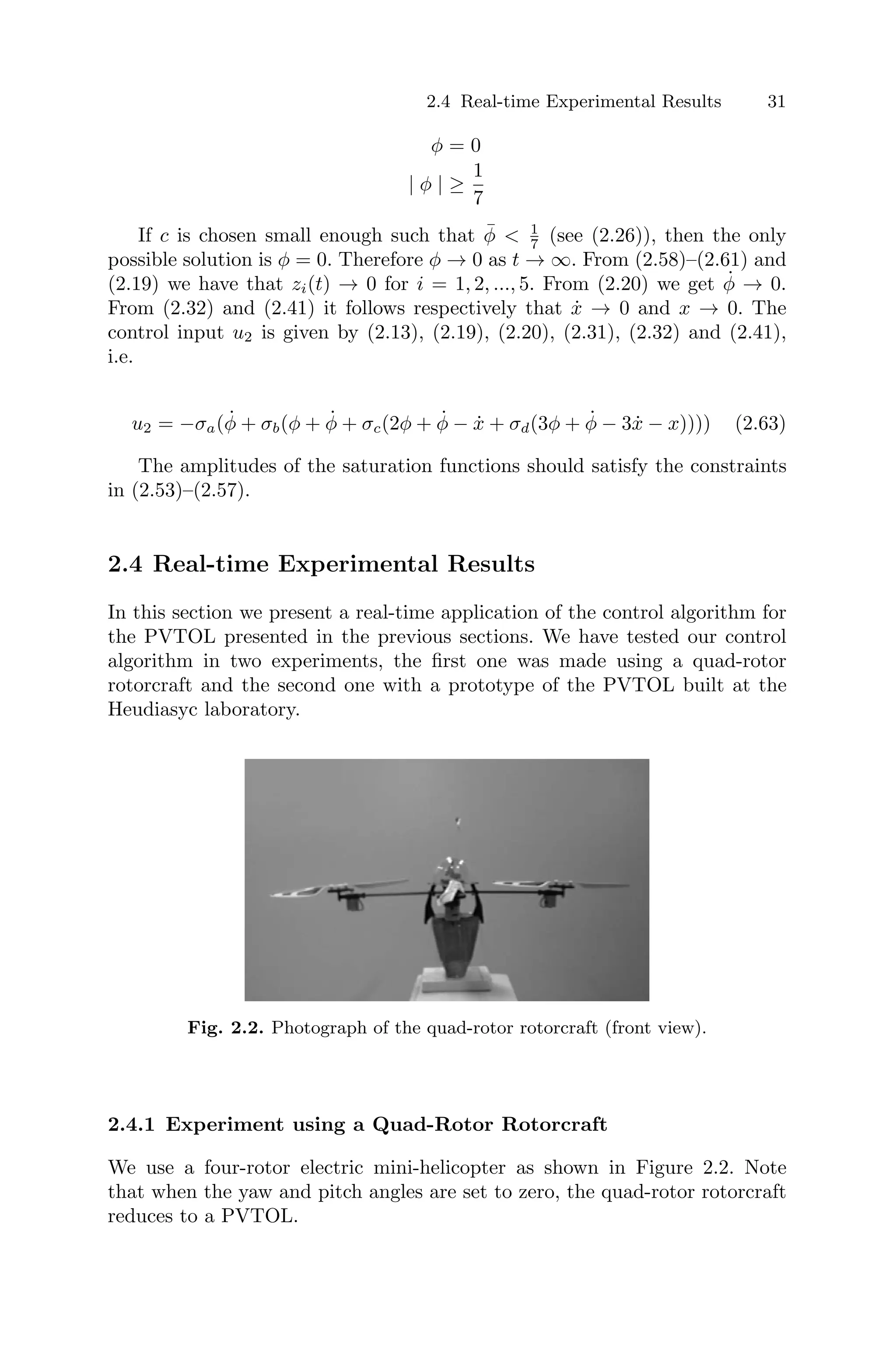
![32 2 The PVTOL Aircraft
In our experiment the pitch and yaw angles are controlled manually by an
experienced pilot. The remaining controls, i.e. the main thrust and the roll
control, are controlled using the control strategy presented in the previous
sections. In the four-rotor helicopter, the main thrust is the sum of the thrusts
of each motor. Pitch movement is obtained by increasing (reducing) the speed
of the rear motor while reducing (increasing) the speed of the front motor.
The roll movement is obtained similarly using the lateral motors.
The radio is a Futaba Skysport 4. The radio and the PC (INTEL Pentium
III) are connected using data acquisition cards (ADVANTECH PCL-818HG
and PCL-726). The connection in the radio is directly made to the joystick
potentiometers for the main thrust and pitch control.
We use the 3D tracker system (POLHEMUS) [46] for measuring the po-
sition and the orientation of the rotorcraft. The Polhemus is connected via
RS232 to the PC.
In Chapter 3, we will give a detailed description of this platform.
We wish to use our control law with a quad-rotor rotorcraft; this helicopter
evolves in 3D and its movements are defined by the variables (x, y, z, ψ, θ, φ).
We are going to assimilate the altitude of the quad-rotor rotorcraft to the
altitude of the PVTOL. This means that we will see y of the PVTOL as z of
the quad-rotor rotorcraft.
The control objective for this experience is to make the quad-rotor ro-
torcraft hover at an altitude of 20 cm i.e. we wish to reach the position
(x, z) = (0, 20) cm while φ = 0◦
.
With respect to the time derivatives, we have simplified the mathematical
computation by setting q̇t
∼
=
qt−qt−T
T , where q is a given variable and T is the
sampling period. In the experiment T = 71 ms.
20 25 30 35 40 45 50 55 60
−5
0
5
10
15
20
25
Time [s]
z
[cm]
Fig. 2.3. Altitude of the quad-rotor rotorcraft.](https://image.slidesharecdn.com/1082115-250606011935-01a0a834/75/Modelling-And-Control-Of-Miniflying-Machines-Advances-In-Industrial-Control-1st-Edition-Pedro-Castillo-50-2048.jpg)
![2.4 Real-time Experimental Results 33
20 25 30 35 40 45 50 55 60
−8
−6
−4
−2
0
2
4
6
8
10
12
Time [s]
x
[cm]
Fig. 2.4. x position of the quad-rotor rotorcraft.
Figures 2.3–2.4 show the performance of the controller when applied to the
helicopter. Take-off and landing were performed autonomously. The choice of
the values for a, b, c, d were carried out satisfying inequalities (2.53)−(2.57).
However these parameters have been tuned experimentally in the sequence as
they appear in the control input u2.
Figure 2.3 describes the gap between the real altitude of the rotorcraft and
the desired altitude. One can notice that it follows satisfactorily the desired
reference. Following the vertical axis, we notice that the position error in the
variable z is of about 3 to 4 cm. In Figure 2.4, one can see the gap between
the real horizontal position of the quad-rotor rotorcraft (according to x) and
the desired position. We note that the rotorcraft position converges towards
the desired position. The final position error is about 2 to 4 cm.
20 25 30 35 40 45 50 55 60
−3
−2
−1
0
1
2
3
4
5
Time [s]
Roll
[°]
Fig. 2.5. Roll angle (φ) of the quad-rotor rotorcraft.](https://image.slidesharecdn.com/1082115-250606011935-01a0a834/75/Modelling-And-Control-Of-Miniflying-Machines-Advances-In-Industrial-Control-1st-Edition-Pedro-Castillo-51-2048.jpg)
![34 2 The PVTOL Aircraft
Figure 2.5 shows the evolution of the φ angle. It can be seen that the control
law achieves convergence of the roll angle to zero, as the helicopter goes up
to the altitude of 20 cm. It also shows the rotorcraft horizontal displacement
in the x-axis.
2.4.2 Experimental Platform Using Vision
In this subsection we have tested the control algorithm using vision [131].
The PVTOL prototype built at Heudiasyc laboratory is shown in Fig-
ure 2.6. The rotors are driven separately by two motors. One motor rotates
clockwise while the second one rotates counter-clockwise. The main thrust
is the sum of the thrusts of each motor. The rolling moment is obtained by
increasing (decreasing) the speed of one motor while decreasing (increasing)
the speed of the second motor.
Fig. 2.6. Photograph of the PVTOL aircraft (front view).
The PVTOL moves on an inclined plane, which defines our 2D workspace.
The PVTOL platform is an experimental setup designed to study the prob-
lems currently found in navigation at low altitude of a small flying object. At
low altitude, GPS and even intertial navigation systems are not enough to
stabilize mini-flying objects. Vision using cameras should provide additional
information to make autonomous flights near the ground possible. For sim-
plicity, at a first stage, we have placed the camera outside the aircraft. In the
future, the camera will be located at the base of the mini-helicopter, pointing
downwards. Note that even when the camera is located outside the flying ob-
ject, we still have to deal with the problems of object localization computation
using cameras and delays in the closed-loop system.
In the platform, a CCD camera Pulnix is located perpendicular to the
plane at a fixed altitude and provides an image of the whole workspace. We
have used an acquisition card PCI-1409 of National Instruments Company.
The camera is linked to the PC dedicated to the vision part (which will be](https://image.slidesharecdn.com/1082115-250606011935-01a0a834/75/Modelling-And-Control-Of-Miniflying-Machines-Advances-In-Industrial-Control-1st-Edition-Pedro-Castillo-52-2048.jpg)
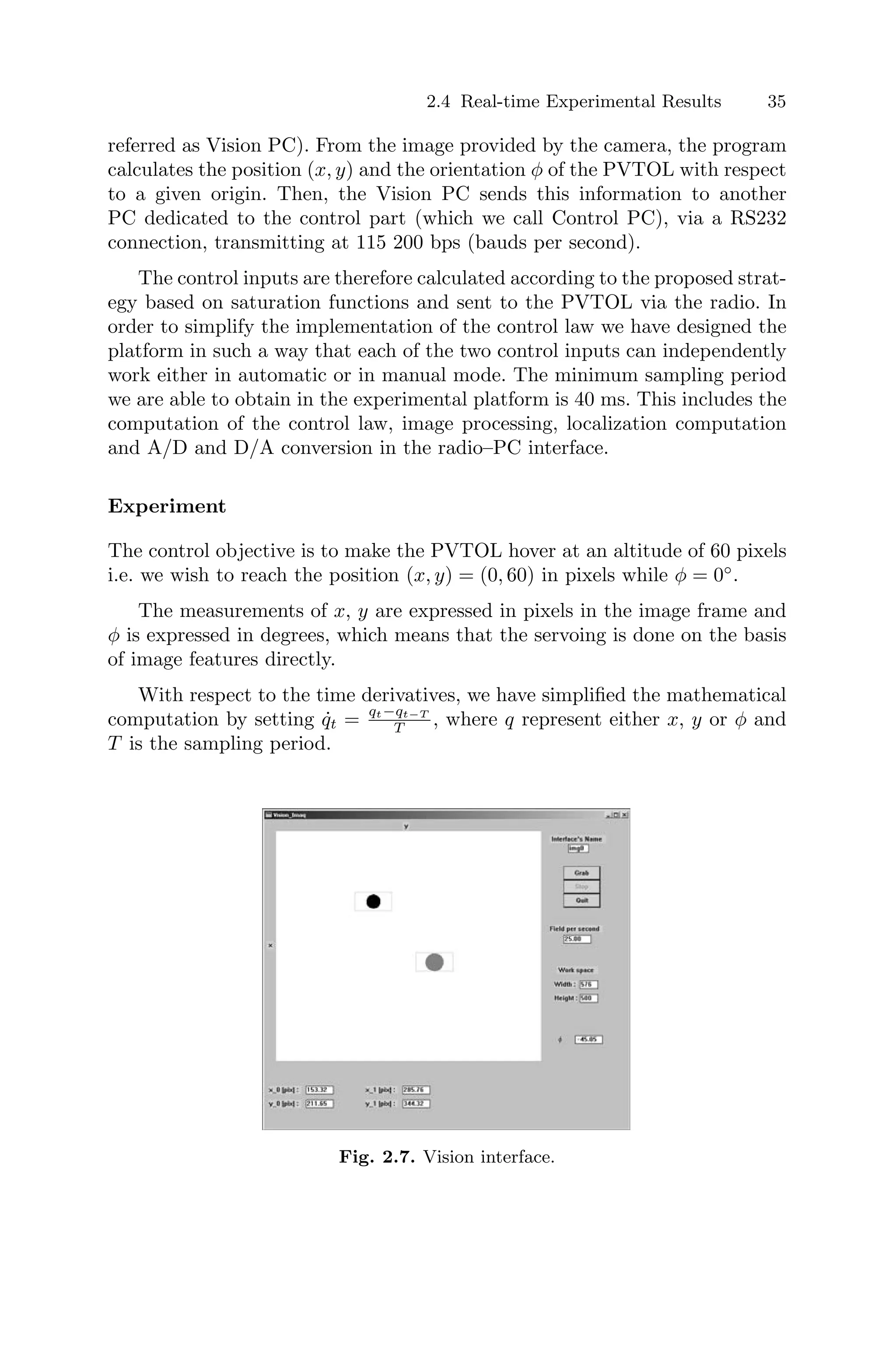
![36 2 The PVTOL Aircraft
In Figure 2.7, the results of the image acquisition program are shown. We
clearly see the detection of two points located on the PVTOL prototype. From
the measurement of these two points, we compute the position x, y and the
angle φ of the system.
Figures 2.8–2.10 show the performance of the controller when applied to
the PVTOL aircraft. Hovering at 60 pixels as well as following a horizontal
trajectory were performed satisfactorily. The choice of the values for a, b, c,
d were carried out satisfying inequalities (2.53)–(2.57). However these param-
eters have been tuned experimentally in the sequence as they appear in the
control input u2.
In Figure 2.8, one can see the gap between the real horizontal position
of the PVTOL in the x-axis and the desired position. In the x-axis, 1 cm
corresponds to 5 pixels. This means that the error position is about 2 to 3
cm.
Figure 2.9 presents the gap between the real PVTOL altitude and the
desired altitude. One can notice that the PVTOL follows the desired reference.
In the vertical y-axis, 1 cm corresponds to 2.5 pixels. This means that the
vertical position error is about 2 to 3 cm.
Figure 2.10 shows the evolution of the φ-angle In this figure, one can see
that the control law achieves convergence of the φ-angle to zero. Therefore,
the difference between the real trajectory and desired one is due to friction.
The results are nevertheless very satisfactory.
0 10 20 30 40 50 60 70
−20
−15
−10
−5
0
5
10
Time [sec]
x
[pixel]
1 [cm] = 5 [pix]
Fig. 2.8. Position [x] of the PVTOL.](https://image.slidesharecdn.com/1082115-250606011935-01a0a834/75/Modelling-And-Control-Of-Miniflying-Machines-Advances-In-Industrial-Control-1st-Edition-Pedro-Castillo-54-2048.jpg)