Downloaded 333 times
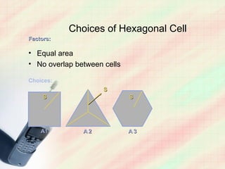
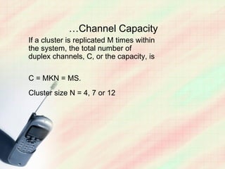
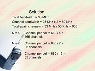
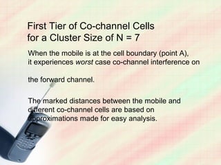
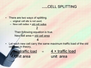
![How to Locate Co-channel
Cells in a Cellular System
A
In this example,
A N = 19
( i.e.,
i = 3,
A
j = 2)
A
A
Adapted from
[Oet83] © IEEE.
A
A](https://image.slidesharecdn.com/mobilecommunicationconcepts-121211121522-phpapp01/85/Mobile-communication-concepts-11-320.jpg)
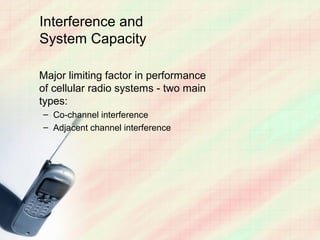
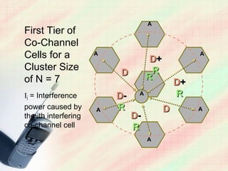
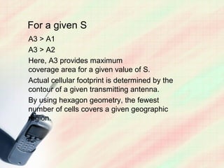
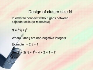
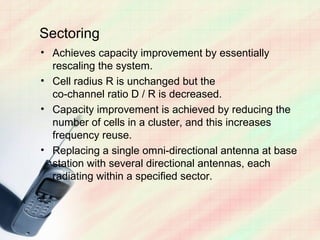
![For a hexagonal geometry
D / R =√(3N) = Q - co-channel
reuse ratio
S / I = [√(3N) ] n / io](https://image.slidesharecdn.com/mobilecommunicationconcepts-121211121522-phpapp01/85/Mobile-communication-concepts-21-320.jpg)
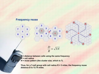
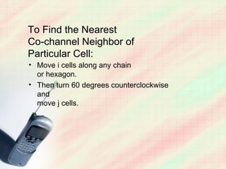
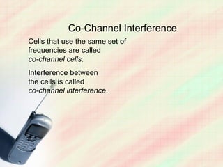
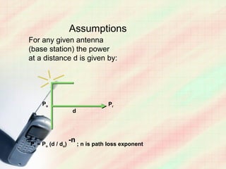
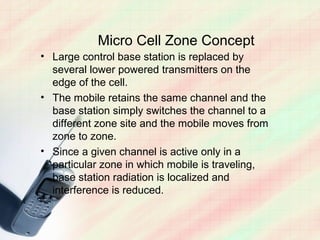
![Maximum co-channel interface –
when mobile is at cell boundary.
For N = 7
S / I~R-4 /
[ 2(D-R)-4+2(D+R)-4+ 2D-4]](https://image.slidesharecdn.com/mobilecommunicationconcepts-121211121522-phpapp01/85/Mobile-communication-concepts-22-320.jpg)
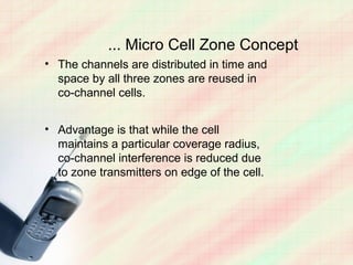
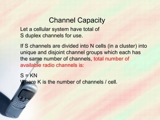
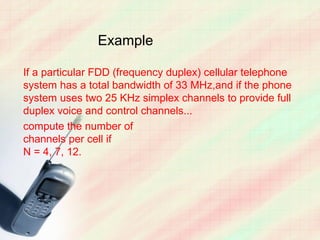
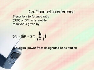
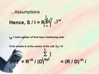
![Microwave or
fiber optic link
Zone Selector
Zone Selector
Base
station
The Micro
Tx/R Tx/Rx Cell Concept
x
(Adapted from
[Lee91b] ©
Tx/R IEEE)
x](https://image.slidesharecdn.com/mobilecommunicationconcepts-121211121522-phpapp01/85/Mobile-communication-concepts-35-320.jpg)
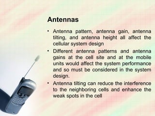

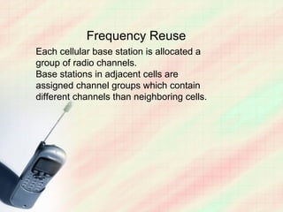
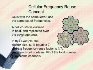
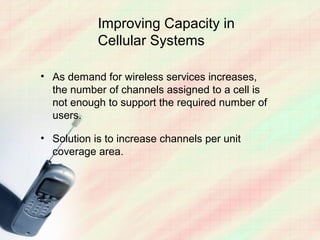
1. Cellular networks reuse frequencies across cells to increase capacity. Neighboring cells are assigned different channel groups to reduce interference. 2. The size of the frequency reuse cluster, channel allocation strategies, and techniques like cell splitting, sectoring, and microcells can improve capacity. 3. Key factors that impact network performance are co-channel and adjacent channel interference, which frequency planning and antenna configurations aim to minimize.


