
Recommended
More Related Content
Similar to mel346-26.pptgrehdhdjhtdhxtrjrgfhjdrybysyer
Similar to mel346-26.pptgrehdhdjhtdhxtrjrgfhjdrybysyer (20)
Recently uploaded
Recently uploaded (20)
mel346-26.pptgrehdhdjhtdhxtrjrgfhjdrybysyer
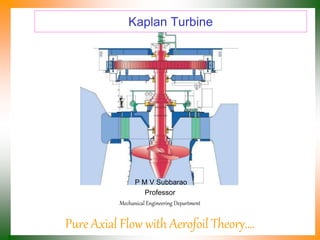
- 1. Kaplan Turbine P M V Subbarao Professor Mechanical Engineering Department Pure Axial Flow with Aerofoil Theory….
- 2. Ub Vwi Vai Vfi Vri Vwi Ub Vai Vfi Vri The Fast Machine for A Low Head
- 4. Kaplan Turbine • The kaplan turbine is a great development of early 20th century. • Invented by Prof. Viktor Kaplan of Austria during 1913 – 1922. • The Kaplan is of the propeller type, similar to an airplane propeller. • The difference between the Propeller and Kaplan turbines is that the Propeller turbine has fixed runner blades while the Kaplan turbine has adjustable runner blades. • It is a pure axial flow turbine uses basic aerofoil theory. • The kaplan's blades are adjustable for pitch and will handle a great variation of flow very efficiently. • They are 90% or better in efficiency and are used in place some of the old (but great) Francis types in a good many of installations. • They are very expensive. • The kaplan turbine, unlike all other turbines, the runner's blades are movable. • The application of Kaplan turbines are from a head of 2m to 40m.
- 6. Major Kaplan Plants in Karnataka, India S.No. Station No. Units × unit Size, MW Design Head Speed rpm Design Discharge, Cumecs 1 LPH 2 × 27.5 29.5 200 101 2 Kadra 3 × 50 32.0 142.86 175.5 3 Kodasalli 3 × 40 37.0 166.67 123 4. Almatti 1 × 15 5 × 55 24.09 187.50 26.69 115.4
- 7. Specific Speed of Kaplan Turbine • Using statistical studies of schemes, F. Schweiger and J. Gregory established the following correlation between the specific speed and the net head for Kaplan turbines: 486 . 0 827 . 39 H Ns 4 5 H P N Ns P in watts.
- 8. The Schematic of Kaplan Turbine
- 9. Major Parts of A Kaplan Turbine
- 10. Superior Hydrodynamic Features Section of Guide Wheel Runner Essential for High Efficiency at low Heads
- 11. Classification of Kaplan Turbines • The Kaplan turbine can be divided in double and single regulated turbines. • A Kaplan turbine with adjustable runner blades and adjustable guide vanes is double regulated while one with only adjustable runner blades is single regulated. • The advantage of the double regulated turbines is that they can be used in a wider field. • The double regulated Kaplan turbines can work between 15% and 100% of the maximum design discharge; • the single regulated turbines can only work between 30% and 100% of the maximum design discharge.
- 13. CAVITATION • Cavitation occurs especially at spots where the pressure is low. • In the case of a Kaplan turbine, the inlet of the runner is quite susceptible to it. • At parts with a high water flow velocity cavitation might also arise. • The major design criteria for blades is : Avoid Cavitation. • First it decreases the efficiency and causes crackling noises. • The main problem is the wear or rather the damage of the turbine’s parts such as the blades. • Cavitation does not just destroy the parts, chemical properties are also lost.
- 14. The suction head • The suction head Hs is the head where the turbine is installed; • if the suction head is positive, the mean line of turbine is located above the trail water; • if it is negative, the mean line of turbine is located under the trail water. • To avoid cavitation, the range of the suction head is limited. • The maximum allowed suction head can be calculated using the following equation: net de vap atm s H g V g p p H 2 2 net de s gH V N 2 5241 . 1 2 46 . 1
- 15. Design of Guide Wheel Dgo N gH k D ug go 2 60 kug 1.3 to 2.25 : Higher values for high specific speeds Number of guide vanes : 8 to 24 : Higher number of vanes for large diameter of guide wheel.
- 16. Outlines of Kaplan Runner Whirl Chamber Guide Vanes a b The space between guide wheel outlet and kaplan runner is known as Whirl Chamber. a=0.13 Drunner & b=0.16 to 0.2 Drunner.
- 17. Design of Kaplan Runner Drunner Dhub
- 19. Adaptation Mechanism inside the Hub
- 20. Inside the Hub
- 21. Parts of Runner
- 22. Hub diameter • The hub diameter Di can be calculated with the following equation: s runner hub N D D 0951 . 0 25 . 0
- 23. Runner diameter section The runner diameter can be calculated by the following equation: N H N D s runner 60 602 . 1 79 . 0 5 . 84 4 3 H Q N Ns
- 24. Generic Designs for Micro Hydel Plants
- 25. Hydrodynamics of Kaplan Blade
- 26. DESIGN OF THE BLADE Two different views of a blade