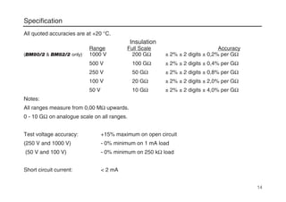
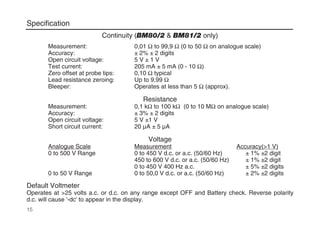
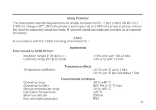
M
BM80/2 Series
Multi-Voltage Insulation and Continuity Tester
User Guide
Guide de l’utilisateur
Gebrauchsanleitung
Guía del usuario
To buy, sell, rent or trade-in this product please click on the link below:
http://www.avionteq.com/Megger-BM80-2-Multi-Voltage-Analogue-Digital-Insulation-and-Continuity-Tester.aspx
www.avionteq.com
Contents
Safety Warnings 2
Notes 3
General Description 4 - 5
Operation
Testing is automatically inhibited if... 6
Voltage testing on high energy systems 6
Auto-shut Off 6
Insulation Tests (MΩ) 7
Polarization Index Testing 7
Continuity Testing (Ω) 8
Continuity Bleeper ( ) 8
Zeroing of Test Lead Resistance 8
Resistance Tests (kΩ) 9
Voltage Tests (V) 9
Live Circuit Warning 9
Battery Check ( ) 10
Battery Replacement 10
Fuse Checking and Replacement 10
Application Notes
Preventive Maintenance 11
Insulation Testing Concepts 12-13
Specification 14-17
Typical Terminal Voltage Characteristics 18
Accessories 19
Repair and Warranty 20
Mode d’emploi 22 - 43
Betriebsanleitung 44 - 65
Instrucionnes de Uso 66 - 87
1
2
SAFETY WARNINGS
• Safety Warnings and Precautions must be read and understood before
the instrument is used. They must be observed during use.
• The circuit under test must be de-energized and isolated before
connections are made except for voltage measurement.
• Circuit connections must not be touched during a test.
• After insulation tests, capacitive circuits must be allowed to discharge
before disconnecting the test leads.
• The Live Circuit Warning and Automatic Discharge are additional safety
features and should not be regarded as a substitute for normal safe
working practice.
• Replacement fuses must be of the correct type and rating.
• Test leads, including crocodile clips, must be in good order, clean and
have no broken or cracked insulation.
• U.K. Safety Authorities recommend the use of fused test leads when
measuring voltage on high energy systems.
NOTE
THIS INSTRUMENT MUST ONLY BE USED BY SUITABLY TRAINED AND COMPETENT PERSONS.
Notes
BEFORE USING THE INSTRUMENT, follow
the separate instructions provided to fit either
the locking or non-locking test button. Megger
Limited recommend the fitting of the non-
locking test button. Hands free operation is
provided on all ranges except the insulation
ranges. If the locking button is fitted, extra care
must be taken.
Symbols used on the instrument:
Risk of electric shock.
Refer to User Guide.
Equipment protected throughout by
Double Insulation (Class II).
Equipment complies with current EU
Directives.
3
NOTE
Users of this equipment and or their employers are reminded that Health and Safety Legislation require them
to carry out valid risk assessments of all electrical work so as to identify potential sources of electrical danger
and risk of electrical injury such as from inadvertent short circuits. Where the assessments show that the risk
is significant then the use of fused test leads constructed in accordance with the HSE guidance note GS38
‘Electrical Test Equipment for use by Electricians’ should be used.Users of this equipment and or their
employers are reminded that Health and Safety Legislation require them to carry out valid risk assessments
of all electrical work so as to identify potential sources of electrical danger and risk of electrical injury such as
from inadvertent short circuits. Where the assessments show that the risk is significant then the use of fused
test leads constructed in accordance with the HSE guidance note GS38 ‘Electrical Test Equipment for use by
Electricians’ should be used.
General Description
The BM80/2 Series instruments are battery
powered Insulation and Continuity testers, with a
measurement capability from 0,01 Ω Continuity
to 200 GΩ Insulation.
Offering multi-voltage facilities, the instruments
take full advantage of microprocessor
technology and feature a large liquid crystal
display combining digital and analogue
readings. The analogue display has the benefit
of indicating trends and fluctuations in
readings, while the digital readout gives direct
accurate results.
The BM80/2 Series instruments have the
unique option of either a locking or non-locking
button which is user selected. The chosen test
button is easily pushed into the instrument
casing without the use of a tool. The procedure
for inserting the test button is provided on the
separate instruction sheet included with the
test buttons.
A customized connector on the top of the
instrument enables the optional Megger SP6F
Switched probe to be used for two handed
probe operation.
The TEST button is used to initiate the
insulation tests, for operating the null facility
and for adjusting the auto shut-off time. Grey
markings on the range label denotes when the
use of the TEST button is necessary. All other
tests (Voltage, Continuity and Resistance)
have the advantage of hands free operation
and are activated when the probes make
contact.
The 250 V, 500 V and 1000 V ranges can be
used to test electrical installations in
compliance with BS7671 (16th Edition IEE
Wiring Regulations) IEC364 and HD384, since
each range has a 1 mA minimum test current
at the minimum pass values of insulation
specified in these documents. The 100 V
range is ideal for testing telecommunications
equipment which would be damaged by higher
voltages. The 50 V range is useful for testing
sensitive equipment, such as electronic
components, and computer peripherals.
Available as an optional accessory, the
Megger DLB Downloading Base can be fitted
for realtime downloading of measured test
4
General Description
results to a Palmtop, Laptop or Personal
computer via an RS232 serial lead. The
optional miniature clip-on current transducer
MCC10 enables the instrument to measure
a.c. currents from 1 A to 10 A.
Instrument power is supplied by six 1,5 V
alkaline battery cells, which are constantly
monitored. When battery power is nearly
exhausted, the symbol appears on the
display. Remaining battery life can be
monitored at any time using the battery check
switch position. This is beneficial before going
on-site, to ensure enough battery power for the
day’s work.
Designed to IEC1010-1 the BM80/2 Series
are protected against connection to a 440 V
Category III supply. The instruments have a
basic accuracy of ± 2% at 20 °C.
The instruments are waterproof and dustproof
to IP54. This helps maintain accuracy and
ensures maximum reliability in harsh
environments.
5
Operation
Testing is automatically inhibited if......
• An external voltage >55 V is present when
switched to any Insulation position above
50 V.
• An external voltage >25 V is present on all
other ranges (excluding Voltmeter
position).
The external voltage is indicated on the display
and the bleeper sounds intermittently.
Voltage Testing on High Energy Systems
Use extreme care when using or measuring
voltages above 30 V, particularly in high
energy systems. Fused test leads are available
as optional accessories. These are strongly
recommended for use when making voltage
tests. (GS38 H.S.E document).
Auto-shut Off
To conserve battery life, Auto-shut Off
(preceded by a series of bleeps) operates after
12 minutes of instrument inactivity in all
insulation test switch positions, and after 5
minutes of instrument inactivity in all other
switch positions. If desired, the 5 minute shut-
off can be changed to 60 minutes (non
insulation test switch positions). To do this, first
perform a battery check, then press the TEST
button twice to show (➔60).
If an insulation test, or OFF is subsequently
selected, the shut-off time reverts to the default
times. It is therefore not possible to generate
dangerous voltages for more than 12 minutes,
even with a locking test button.
To restore operation after Auto-shut Off, select
OFF followed by the required switch position.
Note: Auto-shut Off has a small power
consumption and it is recommended that the
instrument is switched to OFF when not in use.
This is particularly important at the end of the
working day, since no battery power is used in
the OFF position.
6
The circuit under test must be completely de-energized
and isolated before test connections are made.
Operation
Insulation Tests (MΩ)
Insulation tests operate only when the TEST
button is pressed. (See the separate
instructions for fitting the TEST button). These
tests produce high voltages at the terminals
and are initiated when the TEST button is
pressed. When the TEST button is released,
the reading will be held for a few seconds, the
item under test will automatically be
discharged, and the capacitive charge decay
shown on the Live Circuit Warning voltmeter.
When the 1 kV range has been selected
(BM80/2 & BM82/2 only) and the TEST
button pressed, there will be a safety delay of
3 seconds and ‘1000 V’ will flash before the
test voltage is applied. This delay only occurs
as a warning the first time that the button is
pressed after the range has been selected.
The delay will not occur on subsequent tests.
1. Set the selector switch to the test
voltage required.
2. Connect the test leads, first to the
instrument, and then to the isolated
item under test.
3. Press the TEST button to activate the test
voltage.
4. Release the TEST button at the end of the
test. The reading will hold for a few
seconds.
5. Any capacitive circuits charged during a
test will automatically discharge. If
significant voltage remains the voltage
warning will occur.
6. Remove the test leads only when no
voltage is indicated.
Polarization Index Testing
Polarization Index (PI) is the term applied to
the Dielectric Absorption Ratio when
resistance values are measured after 1 minute
and again after 10 minutes. Polarization Index
is then the resistance value after 10 minutes
divided by the resistance value after 1 minute.
The test can be run at any voltage.
More detailed information on PI Testing and
value assessment can be found in Megger
Limited publications listed in the Accessories
page.
7
Continuity Testing (Ω)
(BM80/2 & BM81/2 only)
The continuity tests are activated when the
probes make contact. The test operates
without the need to press the TEST button.
When the test leads are removed the reading
will hold for a few seconds and then reset.
This range is not suitable for diode testing
since the automatic contact detector will not be
activated when connected to a diode. The kΩ
range can be used for diode testing.
1. Set the selector switch to Ω.
2. Connect the test leads. The pointer will
appear when connection to <10 MΩ is
made.
3. The test will activate automatically.
4. After the test probes are disconnected, the
reading will be held for a few seconds.
Continuity Bleeper ( )
(BM80/2 & BM81/2 only)
The continuity bleeper sounds continuously
when less than 5 Ω is detected. Short bleeps
will sound for resistances lower than a few kΩ
and above 5 Ω. If contact to less than 5 Ω is
maintained for five seconds, the bleeper stops,
and the display shows the measured
resistance.
1. Set the selector switch to .
2. Connect the test leads.
Zeroing of Test Lead Resistance
(BM80/2 & BM81/2 only)
The resistance of the test leads can be nulled
on the continuity ranges. To zero the
resistance (up to 9,99 Ω), short the test leads
together, wait for a stable reading, and press
the TEST button. The symbol will appear to
indicate the zero has been adjusted.
1. Select either Continuity range.
2. Short the test leads across a known good
conductor.
3. When the reading has stabilized, press the
TEST button. A short ‘bleep’ will sound
and the zero offset symbol will appear.
4. To release the zero offset press the test
button again or switch the instrument off.
8
Operation
Resistance Tests (kΩ)
This is a low voltage (5 V) low current (20 µA)
test for sensitive electronic equipment. It
operates in the same way as the continuity
ranges. This range can be used for diode
testing.
1. Set the selector switch to kΩ.
2. Connect the test leads.
3. The test will activate automatically.
Voltage Tests (V)
The measured a.c. or d.c. voltage is indicated
on the display. The analogue scale display can
be toggled between the default range of 0 to
500 V (1 V resolution) or the 1 to 50 V (0,1 V
resolution) range by pressing the TEST button.
When a.c. volts are detected the ----- symbol
will appear next to the 'V'. The presence of
negative d.c. is indicated by '-dc' on the
display, but no reading is given.
If the voltmeter operation is in question, test the
voltmeter on a known source.
1. Set the selector switch to V.
2. Connect the test leads.
3. After a short settle time,the reading will be
displayed automatically.
Live Circuit Warning
When more than 25 V is applied to the
terminals, the instrument defaults to a
voltmeter on all switch positions except OFF
and Battery Check. In addition, the audible
bleeper will sound on all switch positions
except OFF and V. All selected tests will be
inhibited except for Insulation tests of 100 V
and above, which will remain available until the
voltage exceeds 55 V.
Note: If the 500 mA fuse has ruptured, the
voltmeter will continue to operate for voltages
greater than 100 V at 50 Hz.
9
Battery Check
The instrument will automatically indicate a
battery low condition by the display of - .
To monitor the battery power level, select the
Battery Check position. The instrument will then
measure the battery voltage under a simulated
load. This value will be displayed. The analogue
arc represents the remaining battery life. A full
arc is equivalent to about 9 V and when the arc
is at its minimum the battery voltage will be
about 6 V.
Battery Replacement
When the low battery symbol appears,
the cells are nearly exhausted and should be
replaced as soon as possible. Use Alkaline
cells IEC LR6 (AA) only. To install or replace
the cells, disconnect the test leads, switch the
instrument to OFF and loosen the captive
screws on the base of the instrument, holding
the battery compartment cover in place.
Remove the cover and lift out the cells. Ensure
that the replacement cells are fitted with the
correct polarity in accordance with the label in
the battery compartment. Replace and re-
secure the battery compartment cover.
Remove the cells if the instrument is not going
to be used for an extended period of time.
Fuse Checking and Replacement
To check the instrument fuse, switch to an
insulation range and press the TEST button.
The symbol will appear if the fuse is
ruptured.
N.B. the voltmeter will continue to operate for
voltages greater than 100 V at 50 Hz.
To replace the fuse, disconnect the test leads,
switch the instrument OFF and loosen the
captive screws holding the battery
compartment cover in place. Use only a
500 mA (F) 440 V, 32 mm x 6 mm ceramic use
of high breaking capacity HBC 10 kA min.
Glass fuses MUST NOT be fitted. Remove the
cover and replace the fuse. Replace and re-
secure the battery compartment cover.
10
Application Notes
11
Preventive Maintenance
The proverb ‘A stitch in time saves nine’
inspired the title of an Megger Limited booklet
on insulation testing, as it neatly sums up the
benefits of preventative maintenance. The
savings come in financial terms from costly
repairs, lost production, lost profits and in
human terms, from lives saved in the event of
dangerous electrical faults.
Regular insulation testing of electrical
equipment can help to detect deteriorating
insulation. The effects which cause insulation
to deteriorate include mechanical damage,
vibration, excessive heat or cold, dirt, oil,
moisture and localized voltage stresses - all of
which can arise on most industrial or utility
equipment.
Insulation tests are sometimes used in
isolation as absolute measures of the quality
of the insulation. This is most appropriate
when equipment is being installed and
checked for compliance with a specified ‘Pass’
level. For operational equipment the key
factors are trends in the insulation readings.
It is therefore important that records of
insulation readings are kept, relating to each
piece of equipment or ‘Asset’ in your testing
regime. Megger Limited supplies test record
cards to assist with such record keeping.
There are also a number of influences on the
insulation readings - temperature, humidity
and surface leakage for example and a range
of test techniques have been developed to
help with the interpretation of your insulation
tests.
Test Record Example
12
Insulation Testing Concepts
Insulation resistance can be considered by
applying Ohm’s Law. The measured
resistance is determined from the applied
voltage divided by the resultant current,
V
R = I
There are two further important factors to be
considered. These are:
(i) the nature of the current through
and/or over the insulation, and:
(ii) the length of time for which the test
voltage is applied. These two factors
are linked.
The total current that flows is made up of three
separate currents:-
1) Capacitance charging current. This current
is initially high and drops as the insulation
becomes charged up to the applied
voltage.
2) Absorption current. This current is also
initially high but drops at a much slower
rate than the charging current.
3) Conduction or Leakage current.This is a
small steady current that can be sub-
divided into two:-
(a) A current flowing along conduction paths
through the insulation material.
(b) A current flowing along conduction
paths over the surface of the insulation
material.
As the total current depends upon the time for
which the voltage is applied, Ohm’s Law
theoretically applies at infinite time.
The charging current falls relatively rapidly as
the equipment under test becomes charged
up. The actual length of time depends upon
the size and capacitance of the item under
test.
Larger items with more capacitance will take
Application Notes
longer e.g. long supply cables. The absorption
current decreases relatively slowly compared
with the charging current. In essence it
depends upon the nature of the insulation
material.
The conduction or leakage current builds up
quickly to a steady value and then remains
constant for a particular applied voltage under
stable conditions. It is this current that is
affected by moisture, dirt etc. and the degree
to which it flows bears a direct relation to the
quality of the insulation, and consequently to
the value of the insulation resistance
measured. An increase in the leakage current
is a pointer to possible future problems.
13
Specification
All quoted accuracies are at +20 °C.
Insulation
Range Full Scale Accuracy
(BM80/2 & BM82/2 only) 1000 V 200 GΩ ± 2% ± 2 digits ± 0,2% per GΩ
500 V 100 GΩ ± 2% ± 2 digits ± 0,4% per GΩ
250 V 50 GΩ ± 2% ± 2 digits ± 0,8% per GΩ
100 V 20 GΩ ± 2% ± 2 digits ± 2,0% per GΩ
50 V 10 GΩ ± 2% ± 2 digits ± 4,0% per GΩ
Notes:
All ranges measure from 0,00 MΩ upwards.
0 - 10 GΩ on analogue scale on all ranges.
Test voltage accuracy: +15% maximum on open circuit
(250 V and 1000 V) - 0% minimum on 1 mA load
(50 V and 100 V) - 0% minimum on 250 kΩ load
Short circuit current: < 2 mA
14
Continuity (BM80/2 & BM81/2 only)
Measurement: 0,01 Ω to 99,9 Ω (0 to 50 Ω on analogue scale)
Accuracy: ± 2% ± 2 digits
Open circuit voltage: 5 V ± 1 V
Test current: 205 mA ± 5 mA (0 - 10 Ω)
Zero offset at probe tips: 0,10 Ω typical
Lead resistance zeroing: Up to 9,99 Ω
Bleeper: Operates at less than 5 Ω (approx).
Resistance
Measurement: 0,1 kΩ to 100 kΩ (0 to 10 MΩ on analogue scale)
Accuracy: ± 3% ± 2 digits
Open circuit voltage: 5 V ±1 V
Short circuit current: 20 µA ± 5 µA
Voltage
Analogue Scale Measurement Accuracy(>1 V)
0 to 500 V Range 0 to 450 V d.c. or a.c. (50/60 Hz) ± 1% ±2 digit
450 to 600 V d.c. or a.c. (50/60 Hz) ± 1% ±2 digit
0 to 450 V 400 Hz a.c. ± 5% ±2 digits
0 to 50 V Range 0 to 50,0 V d.c. or a.c. (50/60 Hz) ± 2% ±2 digits
Default Voltmeter
Operates at >25 volts a.c. or d.c. on any range except OFF and Battery check. Reverse polarity
d.c. will cause '-dc' to appear in the display.
15
Specification
Safety Protection
The instruments meet the requirements for double insulation to IEC 1010-1 (1995), EN 61010-1
(1995) to Category III**, 300 Volts phase to earth (ground) and 440 Volts phase to phase, without
the need for separately fused test leads. If required, fused test leads are available as an optional
accessory.
E.M.C.
In accordance with IEC 61326 including amendment No.1
Interference
Error caused by 50/60 Hz hum:
Insulation ranges (100 kΩ to ∞ ) <10% error with 100 µA rms.
Continuity range (0,2 Ω to 50 Ω) <3% error with 1 V rms.
Temperature effects
Temperature coefficient <0,1% per °C up to 1 GΩ
<0,1% per °C per GΩ above 1 GΩ
Environmental Conditions
Operating range -20 to +40 °C
Operating humidity 90% RH at 40 °C max.
Storage temperature range -25 to +65 °C
Calibration Temperature +20 °C
Maximum altitude 2000 m
Dust and water protection IP54
16
Specification
Fuse Use only a 500 mA (F) 440 V 32 x 6 mm ceramic fuse of high
breaking capacity HBC 10 kA minimum. Glass fuses MUST
NOT be fitted
Power Supply Six LR6 Alkaline Cells
Zinc carbon cells are not recommended
Dimensions 220 x 92 x 50 mm
Weight 625g
Cleaning Wipe with a clean cloth dampened with soapy water or
Isopropyl Alcohol (IPA).
**Relates to transient overvoltage likely to be found in fixed installation wiring.
17
Typical Terminal Voltage Characteristics
18
(BM80/2 &
BM82/2 only)
Accessories
Supplied: Part Number
Test lead set 6220-437
Test-&-carry case 6420-112
User Guide 6172-188
Optional:
Fused lead set, FPK8 6111-218
Zip-up carrying case 6420-132
Download Base DLB2 6420-602
Switch Test Probe SP6F 6220-836
Miniature A.C. Current Transducer MCC10 6111-290
Test Record Cards (Pack of 20) 6111-216
Publications
‘A Stitch in Time’ AVTM21-P8B
19
Repair and Warranty
The instrument circuit contains static sensitive
devices, and care must be taken in handling the
printed circuit board. If the protection of an
instrument has been impaired it should not be
used, and be sent for repair by suitably trained
and qualified personnel. The protection is likely to
be impaired if, for example, the instrument shows
visible damage, fails to perform the intended
measurements, has been subjected to prolonged
storage under unfavourable conditions, or has
been exposed to severe transport stresses.
New Instruments are Guaranteed for 1 Year from
the Date of Purchase by the User.
Note: Any unauthorized prior repair or adjustment
will automatically invalidate the Warranty.
Instrument Repair and Spare Parts
For service requirements for Megger Instruments
contact:-
Megger LImited
Archcliffe Road
Dover
Kent CT17 9EN Tel: +44 (0) 1304 502243
England Fax: +44 (0) 1304 207342
OR
Megger
Valley Forge Corporate Center
2621 Van Buren Avenue
Norristown, PA 19403 Tel: +1 (610) 676-8500
U.S.A. Fax: +1 (610) 676-8625
or an approved repair company.
Approved Repair Companies
A number of independent instrument repair
companies have been approved for repair work on
most Megger instruments, using genuine Megger
spare parts. Consult the Appointed Distributor /
Agent regarding spare parts, repair facilities and
advice on the best course of action to take.
Returning an Instrument for Repair
If returning an instrument to the manufacturer for
repair, it should be sent freight pre-paid to the
appropriate address. A copy of the Invoice and of
the packing note should be sent simultaneously by
airmail to expedite clearance through Customs. A
repair estimate showing freight return and other
charges will be submitted to the sender, if
required, before work on the instrument
commences.
20
21
This instrument is manufactured in the United Kingdom.
The company reserves the right to change the specification or design without prior notice.
Megger is a registered trademark
Part No. 6172-188 - Edition 11 - Printed in England 0207
www.megger.com
M
Megger Limited
Archcliffe Road Dover
Kent CT17 9EN ENGLAND
T +44 (0)1 304 502101
F +44 (0)1 304 207342
Megger
4271 Bronze Way, Dallas,
TX 75237-1019 USA
T +1 800 723 2861
T +1 214 333 3201
F +1 214 331 7399
Megger
Z.A. Du Buisson de la Couldre
23 rue Eugène Henaff
78190 TRAPPES France
T +33 (0)1 30.16.08.90
F +33 (0)1 34.61.23.77
OTHER TECHNICAL SALES OFFICES
Toronto CANADA, Sydney AUSTRALIA, Madrid SPAIN, Mumbai INDIA, and the Kingdom of BAHRAIN.
Megger products are distributed in 146 countries worldwide.

Megger-BM802-User-Manual.pdf

  • 1.
    M BM80/2 Series Multi-Voltage Insulationand Continuity Tester User Guide Guide de l’utilisateur Gebrauchsanleitung Guía del usuario To buy, sell, rent or trade-in this product please click on the link below: http://www.avionteq.com/Megger-BM80-2-Multi-Voltage-Analogue-Digital-Insulation-and-Continuity-Tester.aspx www.avionteq.com
  • 2.
    Contents Safety Warnings 2 Notes3 General Description 4 - 5 Operation Testing is automatically inhibited if... 6 Voltage testing on high energy systems 6 Auto-shut Off 6 Insulation Tests (MΩ) 7 Polarization Index Testing 7 Continuity Testing (Ω) 8 Continuity Bleeper ( ) 8 Zeroing of Test Lead Resistance 8 Resistance Tests (kΩ) 9 Voltage Tests (V) 9 Live Circuit Warning 9 Battery Check ( ) 10 Battery Replacement 10 Fuse Checking and Replacement 10 Application Notes Preventive Maintenance 11 Insulation Testing Concepts 12-13 Specification 14-17 Typical Terminal Voltage Characteristics 18 Accessories 19 Repair and Warranty 20 Mode d’emploi 22 - 43 Betriebsanleitung 44 - 65 Instrucionnes de Uso 66 - 87 1
  • 3.
    2 SAFETY WARNINGS • SafetyWarnings and Precautions must be read and understood before the instrument is used. They must be observed during use. • The circuit under test must be de-energized and isolated before connections are made except for voltage measurement. • Circuit connections must not be touched during a test. • After insulation tests, capacitive circuits must be allowed to discharge before disconnecting the test leads. • The Live Circuit Warning and Automatic Discharge are additional safety features and should not be regarded as a substitute for normal safe working practice. • Replacement fuses must be of the correct type and rating. • Test leads, including crocodile clips, must be in good order, clean and have no broken or cracked insulation. • U.K. Safety Authorities recommend the use of fused test leads when measuring voltage on high energy systems. NOTE THIS INSTRUMENT MUST ONLY BE USED BY SUITABLY TRAINED AND COMPETENT PERSONS.
  • 4.
    Notes BEFORE USING THEINSTRUMENT, follow the separate instructions provided to fit either the locking or non-locking test button. Megger Limited recommend the fitting of the non- locking test button. Hands free operation is provided on all ranges except the insulation ranges. If the locking button is fitted, extra care must be taken. Symbols used on the instrument: Risk of electric shock. Refer to User Guide. Equipment protected throughout by Double Insulation (Class II). Equipment complies with current EU Directives. 3 NOTE Users of this equipment and or their employers are reminded that Health and Safety Legislation require them to carry out valid risk assessments of all electrical work so as to identify potential sources of electrical danger and risk of electrical injury such as from inadvertent short circuits. Where the assessments show that the risk is significant then the use of fused test leads constructed in accordance with the HSE guidance note GS38 ‘Electrical Test Equipment for use by Electricians’ should be used.Users of this equipment and or their employers are reminded that Health and Safety Legislation require them to carry out valid risk assessments of all electrical work so as to identify potential sources of electrical danger and risk of electrical injury such as from inadvertent short circuits. Where the assessments show that the risk is significant then the use of fused test leads constructed in accordance with the HSE guidance note GS38 ‘Electrical Test Equipment for use by Electricians’ should be used.
  • 5.
    General Description The BM80/2Series instruments are battery powered Insulation and Continuity testers, with a measurement capability from 0,01 Ω Continuity to 200 GΩ Insulation. Offering multi-voltage facilities, the instruments take full advantage of microprocessor technology and feature a large liquid crystal display combining digital and analogue readings. The analogue display has the benefit of indicating trends and fluctuations in readings, while the digital readout gives direct accurate results. The BM80/2 Series instruments have the unique option of either a locking or non-locking button which is user selected. The chosen test button is easily pushed into the instrument casing without the use of a tool. The procedure for inserting the test button is provided on the separate instruction sheet included with the test buttons. A customized connector on the top of the instrument enables the optional Megger SP6F Switched probe to be used for two handed probe operation. The TEST button is used to initiate the insulation tests, for operating the null facility and for adjusting the auto shut-off time. Grey markings on the range label denotes when the use of the TEST button is necessary. All other tests (Voltage, Continuity and Resistance) have the advantage of hands free operation and are activated when the probes make contact. The 250 V, 500 V and 1000 V ranges can be used to test electrical installations in compliance with BS7671 (16th Edition IEE Wiring Regulations) IEC364 and HD384, since each range has a 1 mA minimum test current at the minimum pass values of insulation specified in these documents. The 100 V range is ideal for testing telecommunications equipment which would be damaged by higher voltages. The 50 V range is useful for testing sensitive equipment, such as electronic components, and computer peripherals. Available as an optional accessory, the Megger DLB Downloading Base can be fitted for realtime downloading of measured test 4
  • 6.
    General Description results toa Palmtop, Laptop or Personal computer via an RS232 serial lead. The optional miniature clip-on current transducer MCC10 enables the instrument to measure a.c. currents from 1 A to 10 A. Instrument power is supplied by six 1,5 V alkaline battery cells, which are constantly monitored. When battery power is nearly exhausted, the symbol appears on the display. Remaining battery life can be monitored at any time using the battery check switch position. This is beneficial before going on-site, to ensure enough battery power for the day’s work. Designed to IEC1010-1 the BM80/2 Series are protected against connection to a 440 V Category III supply. The instruments have a basic accuracy of ± 2% at 20 °C. The instruments are waterproof and dustproof to IP54. This helps maintain accuracy and ensures maximum reliability in harsh environments. 5
  • 7.
    Operation Testing is automaticallyinhibited if...... • An external voltage >55 V is present when switched to any Insulation position above 50 V. • An external voltage >25 V is present on all other ranges (excluding Voltmeter position). The external voltage is indicated on the display and the bleeper sounds intermittently. Voltage Testing on High Energy Systems Use extreme care when using or measuring voltages above 30 V, particularly in high energy systems. Fused test leads are available as optional accessories. These are strongly recommended for use when making voltage tests. (GS38 H.S.E document). Auto-shut Off To conserve battery life, Auto-shut Off (preceded by a series of bleeps) operates after 12 minutes of instrument inactivity in all insulation test switch positions, and after 5 minutes of instrument inactivity in all other switch positions. If desired, the 5 minute shut- off can be changed to 60 minutes (non insulation test switch positions). To do this, first perform a battery check, then press the TEST button twice to show (➔60). If an insulation test, or OFF is subsequently selected, the shut-off time reverts to the default times. It is therefore not possible to generate dangerous voltages for more than 12 minutes, even with a locking test button. To restore operation after Auto-shut Off, select OFF followed by the required switch position. Note: Auto-shut Off has a small power consumption and it is recommended that the instrument is switched to OFF when not in use. This is particularly important at the end of the working day, since no battery power is used in the OFF position. 6 The circuit under test must be completely de-energized and isolated before test connections are made.
  • 8.
    Operation Insulation Tests (MΩ) Insulationtests operate only when the TEST button is pressed. (See the separate instructions for fitting the TEST button). These tests produce high voltages at the terminals and are initiated when the TEST button is pressed. When the TEST button is released, the reading will be held for a few seconds, the item under test will automatically be discharged, and the capacitive charge decay shown on the Live Circuit Warning voltmeter. When the 1 kV range has been selected (BM80/2 & BM82/2 only) and the TEST button pressed, there will be a safety delay of 3 seconds and ‘1000 V’ will flash before the test voltage is applied. This delay only occurs as a warning the first time that the button is pressed after the range has been selected. The delay will not occur on subsequent tests. 1. Set the selector switch to the test voltage required. 2. Connect the test leads, first to the instrument, and then to the isolated item under test. 3. Press the TEST button to activate the test voltage. 4. Release the TEST button at the end of the test. The reading will hold for a few seconds. 5. Any capacitive circuits charged during a test will automatically discharge. If significant voltage remains the voltage warning will occur. 6. Remove the test leads only when no voltage is indicated. Polarization Index Testing Polarization Index (PI) is the term applied to the Dielectric Absorption Ratio when resistance values are measured after 1 minute and again after 10 minutes. Polarization Index is then the resistance value after 10 minutes divided by the resistance value after 1 minute. The test can be run at any voltage. More detailed information on PI Testing and value assessment can be found in Megger Limited publications listed in the Accessories page. 7
  • 9.
    Continuity Testing (Ω) (BM80/2& BM81/2 only) The continuity tests are activated when the probes make contact. The test operates without the need to press the TEST button. When the test leads are removed the reading will hold for a few seconds and then reset. This range is not suitable for diode testing since the automatic contact detector will not be activated when connected to a diode. The kΩ range can be used for diode testing. 1. Set the selector switch to Ω. 2. Connect the test leads. The pointer will appear when connection to <10 MΩ is made. 3. The test will activate automatically. 4. After the test probes are disconnected, the reading will be held for a few seconds. Continuity Bleeper ( ) (BM80/2 & BM81/2 only) The continuity bleeper sounds continuously when less than 5 Ω is detected. Short bleeps will sound for resistances lower than a few kΩ and above 5 Ω. If contact to less than 5 Ω is maintained for five seconds, the bleeper stops, and the display shows the measured resistance. 1. Set the selector switch to . 2. Connect the test leads. Zeroing of Test Lead Resistance (BM80/2 & BM81/2 only) The resistance of the test leads can be nulled on the continuity ranges. To zero the resistance (up to 9,99 Ω), short the test leads together, wait for a stable reading, and press the TEST button. The symbol will appear to indicate the zero has been adjusted. 1. Select either Continuity range. 2. Short the test leads across a known good conductor. 3. When the reading has stabilized, press the TEST button. A short ‘bleep’ will sound and the zero offset symbol will appear. 4. To release the zero offset press the test button again or switch the instrument off. 8
  • 10.
    Operation Resistance Tests (kΩ) Thisis a low voltage (5 V) low current (20 µA) test for sensitive electronic equipment. It operates in the same way as the continuity ranges. This range can be used for diode testing. 1. Set the selector switch to kΩ. 2. Connect the test leads. 3. The test will activate automatically. Voltage Tests (V) The measured a.c. or d.c. voltage is indicated on the display. The analogue scale display can be toggled between the default range of 0 to 500 V (1 V resolution) or the 1 to 50 V (0,1 V resolution) range by pressing the TEST button. When a.c. volts are detected the ----- symbol will appear next to the 'V'. The presence of negative d.c. is indicated by '-dc' on the display, but no reading is given. If the voltmeter operation is in question, test the voltmeter on a known source. 1. Set the selector switch to V. 2. Connect the test leads. 3. After a short settle time,the reading will be displayed automatically. Live Circuit Warning When more than 25 V is applied to the terminals, the instrument defaults to a voltmeter on all switch positions except OFF and Battery Check. In addition, the audible bleeper will sound on all switch positions except OFF and V. All selected tests will be inhibited except for Insulation tests of 100 V and above, which will remain available until the voltage exceeds 55 V. Note: If the 500 mA fuse has ruptured, the voltmeter will continue to operate for voltages greater than 100 V at 50 Hz. 9
  • 11.
    Battery Check The instrumentwill automatically indicate a battery low condition by the display of - . To monitor the battery power level, select the Battery Check position. The instrument will then measure the battery voltage under a simulated load. This value will be displayed. The analogue arc represents the remaining battery life. A full arc is equivalent to about 9 V and when the arc is at its minimum the battery voltage will be about 6 V. Battery Replacement When the low battery symbol appears, the cells are nearly exhausted and should be replaced as soon as possible. Use Alkaline cells IEC LR6 (AA) only. To install or replace the cells, disconnect the test leads, switch the instrument to OFF and loosen the captive screws on the base of the instrument, holding the battery compartment cover in place. Remove the cover and lift out the cells. Ensure that the replacement cells are fitted with the correct polarity in accordance with the label in the battery compartment. Replace and re- secure the battery compartment cover. Remove the cells if the instrument is not going to be used for an extended period of time. Fuse Checking and Replacement To check the instrument fuse, switch to an insulation range and press the TEST button. The symbol will appear if the fuse is ruptured. N.B. the voltmeter will continue to operate for voltages greater than 100 V at 50 Hz. To replace the fuse, disconnect the test leads, switch the instrument OFF and loosen the captive screws holding the battery compartment cover in place. Use only a 500 mA (F) 440 V, 32 mm x 6 mm ceramic use of high breaking capacity HBC 10 kA min. Glass fuses MUST NOT be fitted. Remove the cover and replace the fuse. Replace and re- secure the battery compartment cover. 10
  • 12.
    Application Notes 11 Preventive Maintenance Theproverb ‘A stitch in time saves nine’ inspired the title of an Megger Limited booklet on insulation testing, as it neatly sums up the benefits of preventative maintenance. The savings come in financial terms from costly repairs, lost production, lost profits and in human terms, from lives saved in the event of dangerous electrical faults. Regular insulation testing of electrical equipment can help to detect deteriorating insulation. The effects which cause insulation to deteriorate include mechanical damage, vibration, excessive heat or cold, dirt, oil, moisture and localized voltage stresses - all of which can arise on most industrial or utility equipment. Insulation tests are sometimes used in isolation as absolute measures of the quality of the insulation. This is most appropriate when equipment is being installed and checked for compliance with a specified ‘Pass’ level. For operational equipment the key factors are trends in the insulation readings. It is therefore important that records of insulation readings are kept, relating to each piece of equipment or ‘Asset’ in your testing regime. Megger Limited supplies test record cards to assist with such record keeping. There are also a number of influences on the insulation readings - temperature, humidity and surface leakage for example and a range of test techniques have been developed to help with the interpretation of your insulation tests. Test Record Example
  • 13.
    12 Insulation Testing Concepts Insulationresistance can be considered by applying Ohm’s Law. The measured resistance is determined from the applied voltage divided by the resultant current, V R = I There are two further important factors to be considered. These are: (i) the nature of the current through and/or over the insulation, and: (ii) the length of time for which the test voltage is applied. These two factors are linked. The total current that flows is made up of three separate currents:- 1) Capacitance charging current. This current is initially high and drops as the insulation becomes charged up to the applied voltage. 2) Absorption current. This current is also initially high but drops at a much slower rate than the charging current. 3) Conduction or Leakage current.This is a small steady current that can be sub- divided into two:- (a) A current flowing along conduction paths through the insulation material. (b) A current flowing along conduction paths over the surface of the insulation material. As the total current depends upon the time for which the voltage is applied, Ohm’s Law theoretically applies at infinite time. The charging current falls relatively rapidly as the equipment under test becomes charged up. The actual length of time depends upon the size and capacitance of the item under test. Larger items with more capacitance will take
  • 14.
    Application Notes longer e.g.long supply cables. The absorption current decreases relatively slowly compared with the charging current. In essence it depends upon the nature of the insulation material. The conduction or leakage current builds up quickly to a steady value and then remains constant for a particular applied voltage under stable conditions. It is this current that is affected by moisture, dirt etc. and the degree to which it flows bears a direct relation to the quality of the insulation, and consequently to the value of the insulation resistance measured. An increase in the leakage current is a pointer to possible future problems. 13
  • 15.
    Specification All quoted accuraciesare at +20 °C. Insulation Range Full Scale Accuracy (BM80/2 & BM82/2 only) 1000 V 200 GΩ ± 2% ± 2 digits ± 0,2% per GΩ 500 V 100 GΩ ± 2% ± 2 digits ± 0,4% per GΩ 250 V 50 GΩ ± 2% ± 2 digits ± 0,8% per GΩ 100 V 20 GΩ ± 2% ± 2 digits ± 2,0% per GΩ 50 V 10 GΩ ± 2% ± 2 digits ± 4,0% per GΩ Notes: All ranges measure from 0,00 MΩ upwards. 0 - 10 GΩ on analogue scale on all ranges. Test voltage accuracy: +15% maximum on open circuit (250 V and 1000 V) - 0% minimum on 1 mA load (50 V and 100 V) - 0% minimum on 250 kΩ load Short circuit current: < 2 mA 14
  • 16.
    Continuity (BM80/2 &BM81/2 only) Measurement: 0,01 Ω to 99,9 Ω (0 to 50 Ω on analogue scale) Accuracy: ± 2% ± 2 digits Open circuit voltage: 5 V ± 1 V Test current: 205 mA ± 5 mA (0 - 10 Ω) Zero offset at probe tips: 0,10 Ω typical Lead resistance zeroing: Up to 9,99 Ω Bleeper: Operates at less than 5 Ω (approx). Resistance Measurement: 0,1 kΩ to 100 kΩ (0 to 10 MΩ on analogue scale) Accuracy: ± 3% ± 2 digits Open circuit voltage: 5 V ±1 V Short circuit current: 20 µA ± 5 µA Voltage Analogue Scale Measurement Accuracy(>1 V) 0 to 500 V Range 0 to 450 V d.c. or a.c. (50/60 Hz) ± 1% ±2 digit 450 to 600 V d.c. or a.c. (50/60 Hz) ± 1% ±2 digit 0 to 450 V 400 Hz a.c. ± 5% ±2 digits 0 to 50 V Range 0 to 50,0 V d.c. or a.c. (50/60 Hz) ± 2% ±2 digits Default Voltmeter Operates at >25 volts a.c. or d.c. on any range except OFF and Battery check. Reverse polarity d.c. will cause '-dc' to appear in the display. 15 Specification
  • 17.
    Safety Protection The instrumentsmeet the requirements for double insulation to IEC 1010-1 (1995), EN 61010-1 (1995) to Category III**, 300 Volts phase to earth (ground) and 440 Volts phase to phase, without the need for separately fused test leads. If required, fused test leads are available as an optional accessory. E.M.C. In accordance with IEC 61326 including amendment No.1 Interference Error caused by 50/60 Hz hum: Insulation ranges (100 kΩ to ∞ ) <10% error with 100 µA rms. Continuity range (0,2 Ω to 50 Ω) <3% error with 1 V rms. Temperature effects Temperature coefficient <0,1% per °C up to 1 GΩ <0,1% per °C per GΩ above 1 GΩ Environmental Conditions Operating range -20 to +40 °C Operating humidity 90% RH at 40 °C max. Storage temperature range -25 to +65 °C Calibration Temperature +20 °C Maximum altitude 2000 m Dust and water protection IP54 16
  • 18.
    Specification Fuse Use onlya 500 mA (F) 440 V 32 x 6 mm ceramic fuse of high breaking capacity HBC 10 kA minimum. Glass fuses MUST NOT be fitted Power Supply Six LR6 Alkaline Cells Zinc carbon cells are not recommended Dimensions 220 x 92 x 50 mm Weight 625g Cleaning Wipe with a clean cloth dampened with soapy water or Isopropyl Alcohol (IPA). **Relates to transient overvoltage likely to be found in fixed installation wiring. 17
  • 19.
    Typical Terminal VoltageCharacteristics 18 (BM80/2 & BM82/2 only)
  • 20.
    Accessories Supplied: Part Number Testlead set 6220-437 Test-&-carry case 6420-112 User Guide 6172-188 Optional: Fused lead set, FPK8 6111-218 Zip-up carrying case 6420-132 Download Base DLB2 6420-602 Switch Test Probe SP6F 6220-836 Miniature A.C. Current Transducer MCC10 6111-290 Test Record Cards (Pack of 20) 6111-216 Publications ‘A Stitch in Time’ AVTM21-P8B 19
  • 21.
    Repair and Warranty Theinstrument circuit contains static sensitive devices, and care must be taken in handling the printed circuit board. If the protection of an instrument has been impaired it should not be used, and be sent for repair by suitably trained and qualified personnel. The protection is likely to be impaired if, for example, the instrument shows visible damage, fails to perform the intended measurements, has been subjected to prolonged storage under unfavourable conditions, or has been exposed to severe transport stresses. New Instruments are Guaranteed for 1 Year from the Date of Purchase by the User. Note: Any unauthorized prior repair or adjustment will automatically invalidate the Warranty. Instrument Repair and Spare Parts For service requirements for Megger Instruments contact:- Megger LImited Archcliffe Road Dover Kent CT17 9EN Tel: +44 (0) 1304 502243 England Fax: +44 (0) 1304 207342 OR Megger Valley Forge Corporate Center 2621 Van Buren Avenue Norristown, PA 19403 Tel: +1 (610) 676-8500 U.S.A. Fax: +1 (610) 676-8625 or an approved repair company. Approved Repair Companies A number of independent instrument repair companies have been approved for repair work on most Megger instruments, using genuine Megger spare parts. Consult the Appointed Distributor / Agent regarding spare parts, repair facilities and advice on the best course of action to take. Returning an Instrument for Repair If returning an instrument to the manufacturer for repair, it should be sent freight pre-paid to the appropriate address. A copy of the Invoice and of the packing note should be sent simultaneously by airmail to expedite clearance through Customs. A repair estimate showing freight return and other charges will be submitted to the sender, if required, before work on the instrument commences. 20
  • 22.
  • 23.
    This instrument ismanufactured in the United Kingdom. The company reserves the right to change the specification or design without prior notice. Megger is a registered trademark Part No. 6172-188 - Edition 11 - Printed in England 0207 www.megger.com M Megger Limited Archcliffe Road Dover Kent CT17 9EN ENGLAND T +44 (0)1 304 502101 F +44 (0)1 304 207342 Megger 4271 Bronze Way, Dallas, TX 75237-1019 USA T +1 800 723 2861 T +1 214 333 3201 F +1 214 331 7399 Megger Z.A. Du Buisson de la Couldre 23 rue Eugène Henaff 78190 TRAPPES France T +33 (0)1 30.16.08.90 F +33 (0)1 34.61.23.77 OTHER TECHNICAL SALES OFFICES Toronto CANADA, Sydney AUSTRALIA, Madrid SPAIN, Mumbai INDIA, and the Kingdom of BAHRAIN. Megger products are distributed in 146 countries worldwide.