This is the Highly Detailed factory service repair manual for theMASSEY FERGUSON MF1010 TRACTOR, this Service Manual has detailed illustrations as well as step by step instructions,It is 100 percents complete and intact. they are specifically written for the do-it-yourself-er as well as the experienced mechanic.MASSEY FERGUSON MF1010 TRACTOR Service Repair Workshop Manual provides step-by-step instructions based on the complete dis-assembly of the machine. It is this level of detail, along with hundreds of photos and illustrations, that guide the reader through each service and repair procedure. Complete download comes in pdf format which can work under all PC based windows operating system and Mac also, All pages are printable. Using this repair manual is an inexpensive way to keep your vehicle working properly.
Service Repair Manual Covers:
Dual Dimensions
Condensed Service Data
Front Axle System (Two-Wheel Drive)
Steering System
Front Axle System (Four-Wheel Drive)
Engine and Components
Diesel Fuel System
Cooling System
Electrical System
Clutch
Transmission 1010 Standard
Transmission 1010 HYDRO
Transmission 1020 Standard
Transmission 1020 HYDRO
Rear Axle Center Housing and Differential
Final Drive and Axles
Brakes
Power Take-Off
Hydraulic Lift System
File Format: PDF
Compatible: All Versions of Windows & Mac
Language: English
Requirements: Adobe PDF Reader
NO waiting, Buy from responsible seller and get INSTANT DOWNLOAD, Without wasting your hard-owned money on uncertainty or surprise! All pages are is great to haveMASSEY FERGUSON MF1010 TRACTOR Service Repair Workshop Manual.
Looking for some other Service Repair Manual,please check:
https://www.aservicemanualpdf.com/
Thanks for visiting!
2005 Arctic Cat M7 SNOWMOBILE Service Repair Manualhjmkmd jskemmd
This is the Highly Detailed factory service repair manual for the2005 ARCTIC CAT M7 SNOWMOBILE, this Service Manual has detailed illustrations as well as step by step instructions,It is 100 percents complete and intact. they are specifically written for the do-it-yourself-er as well as the experienced mechanic.2005 ARCTIC CAT M7 SNOWMOBILE Service Repair Workshop Manual provides step-by-step instructions based on the complete dis-assembly of the machine. It is this level of detail, along with hundreds of photos and illustrations, that guide the reader through each service and repair procedure. Complete download comes in pdf format which can work under all PC based windows operating system and Mac also, All pages are printable. Using this repair manual is an inexpensive way to keep your vehicle working properly.
Service Repair Manual Covers:
General Information
Engine
Engine –Related Items
Fuel Systems
Engine Electrical Systems
Chassis Electrical Systems
Steering and Body
Drive Train and Brake Systems
Track / Rear Suspension
Wiring Diagrams
File Format: PDF
Compatible: All Versions of Windows & Mac
Language: English
Requirements: Adobe PDF Reader
NO waiting, Buy from responsible seller and get INSTANT DOWNLOAD, Without wasting your hard-owned money on uncertainty or surprise! All pages are is great to have2005 ARCTIC CAT M7 SNOWMOBILE Service Repair Workshop Manual.
Looking for some other Service Repair Manual,please check:
https://www.aservicemanualpdf.com/
Thanks for visiting!
The document promotes clicking a link to obtain more information. It thanks the reader for their time and directs them to click a specified link in order to learn more details. The overall message is encouraging the reader to follow the given link by promising additional information will become available if they do.
1990 ARCTIC CAT SNOWMOBILE Service Repair Manualhjmkmd jskemmd
This is the Highly Detailed factory service repair manual for the1990 ARCTIC CAT SNOWMOBILE, this Service Manual has detailed illustrations as well as step by step instructions,It is 100 percents complete and intact. they are specifically written for the do-it-yourself-er as well as the experienced mechanic.1990 ARCTIC CAT SNOWMOBILE Service Repair Workshop Manual provides step-by-step instructions based on the complete dis-assembly of the machine. It is this level of detail, along with hundreds of photos and illustrations, that guide the reader through each service and repair procedure. Complete download comes in pdf format which can work under all PC based windows operating system and Mac also, All pages are printable. Using this repair manual is an inexpensive way to keep your vehicle working properly.
Models Covers:
Cougar
Cougar 2-Up
Prowler
Prowler 2-Up
Powder Extreme
Powder Special
Powder Special EFI
Pantera
Panther 440
Panther 550
EXT
EXT 550
EXT 580
EXT 580 Z
EXT 580 EFI
EXT 600
El Tigre EXT
Z 440
ZL 440
ZL 500
ZR 440
ZR 580
ZR 580 EFI
ZR 600
ZRT 600
Service Repair Manual Covers:
General information
Troubleshooting
Lubrication, maintenance and tune-up
Adjustments for special use
Engine
Fuel system carbureted models
Fuel system fuel injected models
Exhaust system
Electrical systems
Oil injection system
Cooling system
Recoll starter
Drive system
Brake, driven shaft, dropcase and driveshaft
Front suspension and steering
Track and rear suspension
Off-season storage
Index
Wiring diagrams
File Format: PDF
Compatible: All Versions of Windows & Mac
Language: English
Requirements: Adobe PDF Reader
NO waiting, Buy from responsible seller and get INSTANT DOWNLOAD, Without wasting your hard-owned money on uncertainty or surprise! All pages are is great to have1990 ARCTIC CAT SNOWMOBILE Service Repair Workshop Manual.
Looking for some other Service Repair Manual,please check:
https://www.aservicemanualpdf.com/
Thanks for visiting!
MERCURY MERCRUISER 496 MAG HO DIAGNOSTICS Service Repair Manual SN:0M000000 a...hjmkmd jskemmd
This document provides service information for technicians working on Mercury Marine engines, including:
- A list of abbreviations and special tools used for diagnostics and repair
- Safety precautions and instructions for how to use the service manual
- General information on wiring harnesses, connectors, ignition systems, and troubleshooting intermittent issues
- Reference charts for technicians to consult when servicing engines
MASSEY FERGUSON MF35 TRACTOR Service Repair Manualhjmkmd jskemmd
This is the Highly Detailed factory service repair manual for theMASSEY FERGUSON MF35 TRACTOR, this Service Manual has detailed illustrations as well as step by step instructions,It is 100 percents complete and intact. they are specifically written for the do-it-yourself-er as well as the experienced mechanic.MASSEY FERGUSON MF35 TRACTOR Service Repair Workshop Manual provides step-by-step instructions based on the complete dis-assembly of the machine. It is this level of detail, along with hundreds of photos and illustrations, that guide the reader through each service and repair procedure. Complete download comes in pdf format which can work under all PC based windows operating system and Mac also, All pages are printable. Using this repair manual is an inexpensive way to keep your vehicle working properly.
Service Repair Manual Covers:
Introduction
General Specifications
Engine
Cooling System
Fuel System and Carburation
Governor Control
Electrical System
Lighting System
Clutch
Transmission
Rear Axle and Hubs
Hydraulic Mechanism and Linkage
Power Take-Off Shaft
Steering
Front Axle
Brakes
Seat, Hood and Fenders
Service Tools and Equipment
File Format: PDF
Compatible: All Versions of Windows & Mac
Language: English
Requirements: Adobe PDF Reader
NO waiting, Buy from responsible seller and get INSTANT DOWNLOAD, Without wasting your hard-owned money on uncertainty or surprise! All pages are is great to haveMASSEY FERGUSON MF35 TRACTOR Service Repair Workshop Manual.
Looking for some other Service Repair Manual,please check:
https://www.aservicemanualpdf.com/
Thanks for visiting!
KUBOTA U15 MICRO EXCAVATOR Service Repair Manualhjmkmd jskemmd
This is the Highly Detailed factory service repair manual for theKUBOTA U15 MICRO EXCAVATOR, this Service Manual has detailed illustrations as well as step by step instructions,It is 100 percents complete and intact. they are specifically written for the do-it-yourself-er as well as the experienced mechanic.KUBOTA U15 MICRO EXCAVATOR Service Repair Workshop Manual provides step-by-step instructions based on the complete dis-assembly of the machine. It is this level of detail, along with hundreds of photos and illustrations, that guide the reader through each service and repair procedure. Complete download comes in pdf format which can work under all PC based windows operating system and Mac also, All pages are printable. Using this repair manual is an inexpensive way to keep your vehicle working properly.
Service Repair Manual Covers:
WSM Mechanism
ⅠProduct engineering section
Ⅱ Service engineering section
WSM Service
ⅠGeneral
Ⅱ Machine Body
Ⅲ Engine
Ⅳ Hydraulic System
Ⅴ. Electrical System
File Format: PDF
Compatible: All Versions of Windows & Mac
Language: English
Requirements: Adobe PDF Reader
NO waiting, Buy from responsible seller and get INSTANT DOWNLOAD, Without wasting your hard-owned money on uncertainty or surprise! All pages are is great to haveKUBOTA U15 MICRO EXCAVATOR Service Repair Workshop Manual.
Looking for some other Service Repair Manual,please check:
https://www.aservicemanualpdf.com/
Thanks for visiting!
KOMATSU WA180-1 WHEEL LOADER Service Repair Manual SN:10001 and uphjmkmd jskemmd
This is the Highly Detailed factory service repair manual for theKOMATSU WA180-1 WHEEL LOADER, this Service Manual has detailed illustrations as well as step by step instructions,It is 100 percents complete and intact. they are specifically written for the do-it-yourself-er as well as the experienced mechanic.KOMATSU WA180-1 WHEEL LOADER Service Repair Workshop Manual provides step-by-step instructions based on the complete dis-assembly of the machine. It is this level of detail, along with hundreds of photos and illustrations, that guide the reader through each service and repair procedure. Complete download comes in pdf format which can work under all PC based windows operating system and Mac also, All pages are printable. Using this repair manual is an inexpensive way to keep your vehicle working properly.
Service Repair Manual Covers:
Engine
Power train
Steering system
Brake system
Work equipment system
Electric and electronic system
Others
File Format: PDF
Compatible: All Versions of Windows & Mac
Language: English
Requirements: Adobe PDF Reader
NO waiting, Buy from responsible seller and get INSTANT DOWNLOAD, Without wasting your hard-owned money on uncertainty or surprise! All pages are is great to haveKOMATSU WA180-1 WHEEL LOADER Service Repair Workshop Manual.
Looking for some other Service Repair Manual,please check:
https://www.aservicemanualpdf.com/
Thanks for visiting!
2010 Yamaha T25A 25HP OUTBOARD Service Repair Manualhjmkmd jskemmd
This is the Highly Detailed factory service repair manual for the2010 YAMAHA T25A 25HP OUTBOARD, this Service Manual has detailed illustrations as well as step by step instructions,It is 100 percents complete and intact. they are specifically written for the do-it-yourself-er as well as the experienced mechanic.2010 YAMAHA T25A 25HP OUTBOARD Service Repair Workshop Manual provides step-by-step instructions based on the complete dis-assembly of the machine. It is this level of detail, along with hundreds of photos and illustrations, that guide the reader through each service and repair procedure. Complete download comes in pdf format which can work under all PC based windows operating system and Mac also, All pages are printable. Using this repair manual is an inexpensive way to keep your vehicle working properly.
Service Repair Manual Covers:
General Information
Specifications
Technical Features and Description
Rigging Information
Troubleshooting
Electrical System
Fuel System
Power Unit
Lower Unit
Bracket Unit
Maintenance
Index
Appendix
File Format: PDF
Compatible: All Versions of Windows & Mac
Language: English
Requirements: Adobe PDF Reader
NO waiting, Buy from responsible seller and get INSTANT DOWNLOAD, Without wasting your hard-owned money on uncertainty or surprise! All pages are is great to have2010 YAMAHA T25A 25HP OUTBOARD Service Repair Workshop Manual.
Looking for some other Service Repair Manual,please check:
https://www.aservicemanualpdf.com/
Thanks for visiting!
car rentals in nassau bahamas | atv rental nassau bahamasjustinwilson0857
At Dash Auto Sales & Car Rentals, we take pride in providing top-notch automotive services to residents and visitors alike in Nassau, Bahamas. Whether you're looking to purchase a vehicle, rent a car for your vacation, or embark on an exciting ATV adventure, we have you covered with our wide range of options and exceptional customer service.
Website: www.dashrentacarbah.com
Top-Quality AC Service for Mini Cooper Optimal Cooling PerformanceMotor Haus
Ensure your Mini Cooper stays cool and comfortable with our top-quality AC service. Our expert technicians provide comprehensive maintenance, repairs, and performance optimization, guaranteeing reliable cooling and peak efficiency. Trust us for quick, professional service that keeps your Mini Cooper's air conditioning system in top condition, ensuring a pleasant driving experience year-round.
2024 State of Marketing Report – by HubspotMarius Sescu
https://www.hubspot.com/state-of-marketing
· Scaling relationships and proving ROI
· Social media is the place for search, sales, and service
· Authentic influencer partnerships fuel brand growth
· The strongest connections happen via call, click, chat, and camera.
· Time saved with AI leads to more creative work
· Seeking: A single source of truth
· TLDR; Get on social, try AI, and align your systems.
· More human marketing, powered by robots
ChatGPT is a revolutionary addition to the world since its introduction in 2022. A big shift in the sector of information gathering and processing happened because of this chatbot. What is the story of ChatGPT? How is the bot responding to prompts and generating contents? Swipe through these slides prepared by Expeed Software, a web development company regarding the development and technical intricacies of ChatGPT!
Product Design Trends in 2024 | Teenage EngineeringsPixeldarts
The realm of product design is a constantly changing environment where technology and style intersect. Every year introduces fresh challenges and exciting trends that mold the future of this captivating art form. In this piece, we delve into the significant trends set to influence the look and functionality of product design in the year 2024.
How Race, Age and Gender Shape Attitudes Towards Mental HealthThinkNow
Mental health has been in the news quite a bit lately. Dozens of U.S. states are currently suing Meta for contributing to the youth mental health crisis by inserting addictive features into their products, while the U.S. Surgeon General is touring the nation to bring awareness to the growing epidemic of loneliness and isolation. The country has endured periods of low national morale, such as in the 1970s when high inflation and the energy crisis worsened public sentiment following the Vietnam War. The current mood, however, feels different. Gallup recently reported that national mental health is at an all-time low, with few bright spots to lift spirits.
To better understand how Americans are feeling and their attitudes towards mental health in general, ThinkNow conducted a nationally representative quantitative survey of 1,500 respondents and found some interesting differences among ethnic, age and gender groups.
Technology
For example, 52% agree that technology and social media have a negative impact on mental health, but when broken out by race, 61% of Whites felt technology had a negative effect, and only 48% of Hispanics thought it did.
While technology has helped us keep in touch with friends and family in faraway places, it appears to have degraded our ability to connect in person. Staying connected online is a double-edged sword since the same news feed that brings us pictures of the grandkids and fluffy kittens also feeds us news about the wars in Israel and Ukraine, the dysfunction in Washington, the latest mass shooting and the climate crisis.
Hispanics may have a built-in defense against the isolation technology breeds, owing to their large, multigenerational households, strong social support systems, and tendency to use social media to stay connected with relatives abroad.
Age and Gender
When asked how individuals rate their mental health, men rate it higher than women by 11 percentage points, and Baby Boomers rank it highest at 83%, saying it’s good or excellent vs. 57% of Gen Z saying the same.
Gen Z spends the most amount of time on social media, so the notion that social media negatively affects mental health appears to be correlated. Unfortunately, Gen Z is also the generation that’s least comfortable discussing mental health concerns with healthcare professionals. Only 40% of them state they’re comfortable discussing their issues with a professional compared to 60% of Millennials and 65% of Boomers.
Race Affects Attitudes
As seen in previous research conducted by ThinkNow, Asian Americans lag other groups when it comes to awareness of mental health issues. Twenty-four percent of Asian Americans believe that having a mental health issue is a sign of weakness compared to the 16% average for all groups. Asians are also considerably less likely to be aware of mental health services in their communities (42% vs. 55%) and most likely to seek out information on social media (51% vs. 35%).
AI Trends in Creative Operations 2024 by Artwork Flow.pdfmarketingartwork
Creative operations teams expect increased AI use in 2024. Currently, over half of tasks are not AI-enabled, but this is expected to decrease in the coming year. ChatGPT is the most popular AI tool currently. Business leaders are more actively exploring AI benefits than individual contributors. Most respondents do not believe AI will impact workforce size in 2024. However, some inhibitions still exist around AI accuracy and lack of understanding. Creatives primarily want to use AI to save time on mundane tasks and boost productivity.
Organizational culture includes values, norms, systems, symbols, language, assumptions, beliefs, and habits that influence employee behaviors and how people interpret those behaviors. It is important because culture can help or hinder a company's success. Some key aspects of Netflix's culture that help it achieve results include hiring smartly so every position has stars, focusing on attitude over just aptitude, and having a strict policy against peacocks, whiners, and jerks.
PEPSICO Presentation to CAGNY Conference Feb 2024Neil Kimberley
PepsiCo provided a safe harbor statement noting that any forward-looking statements are based on currently available information and are subject to risks and uncertainties. It also provided information on non-GAAP measures and directing readers to its website for disclosure and reconciliation. The document then discussed PepsiCo's business overview, including that it is a global beverage and convenient food company with iconic brands, $91 billion in net revenue in 2023, and nearly $14 billion in core operating profit. It operates through a divisional structure with a focus on local consumers.
Content Methodology: A Best Practices Report (Webinar)contently
This document provides an overview of content methodology best practices. It defines content methodology as establishing objectives, KPIs, and a culture of continuous learning and iteration. An effective methodology focuses on connecting with audiences, creating optimal content, and optimizing processes. It also discusses why a methodology is needed due to the competitive landscape, proliferation of channels, and opportunities for improvement. Components of an effective methodology include defining objectives and KPIs, audience analysis, identifying opportunities, and evaluating resources. The document concludes with recommendations around creating a content plan, testing and optimizing content over 90 days.
How to Prepare For a Successful Job Search for 2024Albert Qian
The document provides guidance on preparing a job search for 2024. It discusses the state of the job market, focusing on growth in AI and healthcare but also continued layoffs. It recommends figuring out what you want to do by researching interests and skills, then conducting informational interviews. The job search should involve building a personal brand on LinkedIn, actively applying to jobs, tailoring resumes and interviews, maintaining job hunting as a habit, and continuing self-improvement. Once hired, the document advises setting new goals and keeping skills and networking active in case of future opportunities.
A report by thenetworkone and Kurio.
The contributing experts and agencies are (in an alphabetical order): Sylwia Rytel, Social Media Supervisor, 180heartbeats + JUNG v MATT (PL), Sharlene Jenner, Vice President - Director of Engagement Strategy, Abelson Taylor (USA), Alex Casanovas, Digital Director, Atrevia (ES), Dora Beilin, Senior Social Strategist, Barrett Hoffher (USA), Min Seo, Campaign Director, Brand New Agency (KR), Deshé M. Gully, Associate Strategist, Day One Agency (USA), Francesca Trevisan, Strategist, Different (IT), Trevor Crossman, CX and Digital Transformation Director; Olivia Hussey, Strategic Planner; Simi Srinarula, Social Media Manager, The Hallway (AUS), James Hebbert, Managing Director, Hylink (CN / UK), Mundy Álvarez, Planning Director; Pedro Rojas, Social Media Manager; Pancho González, CCO, Inbrax (CH), Oana Oprea, Head of Digital Planning, Jam Session Agency (RO), Amy Bottrill, Social Account Director, Launch (UK), Gaby Arriaga, Founder, Leonardo1452 (MX), Shantesh S Row, Creative Director, Liwa (UAE), Rajesh Mehta, Chief Strategy Officer; Dhruv Gaur, Digital Planning Lead; Leonie Mergulhao, Account Supervisor - Social Media & PR, Medulla (IN), Aurelija Plioplytė, Head of Digital & Social, Not Perfect (LI), Daiana Khaidargaliyeva, Account Manager, Osaka Labs (UK / USA), Stefanie Söhnchen, Vice President Digital, PIABO Communications (DE), Elisabeth Winiartati, Managing Consultant, Head of Global Integrated Communications; Lydia Aprina, Account Manager, Integrated Marketing and Communications; Nita Prabowo, Account Manager, Integrated Marketing and Communications; Okhi, Web Developer, PNTR Group (ID), Kei Obusan, Insights Director; Daffi Ranandi, Insights Manager, Radarr (SG), Gautam Reghunath, Co-founder & CEO, Talented (IN), Donagh Humphreys, Head of Social and Digital Innovation, THINKHOUSE (IRE), Sarah Yim, Strategy Director, Zulu Alpha Kilo (CA).
Trends In Paid Search: Navigating The Digital Landscape In 2024Search Engine Journal
The search marketing landscape is evolving rapidly with new technologies, and professionals, like you, rely on innovative paid search strategies to meet changing demands.
It’s important that you’re ready to implement new strategies in 2024.
Check this out and learn the top trends in paid search advertising that are expected to gain traction, so you can drive higher ROI more efficiently in 2024.
You’ll learn:
- The latest trends in AI and automation, and what this means for an evolving paid search ecosystem.
- New developments in privacy and data regulation.
- Emerging ad formats that are expected to make an impact next year.
Watch Sreekant Lanka from iQuanti and Irina Klein from OneMain Financial as they dive into the future of paid search and explore the trends, strategies, and technologies that will shape the search marketing landscape.
If you’re looking to assess your paid search strategy and design an industry-aligned plan for 2024, then this webinar is for you.
5 Public speaking tips from TED - Visualized summarySpeakerHub
From their humble beginnings in 1984, TED has grown into the world’s most powerful amplifier for speakers and thought-leaders to share their ideas. They have over 2,400 filmed talks (not including the 30,000+ TEDx videos) freely available online, and have hosted over 17,500 events around the world.
With over one billion views in a year, it’s no wonder that so many speakers are looking to TED for ideas on how to share their message more effectively.
The article “5 Public-Speaking Tips TED Gives Its Speakers”, by Carmine Gallo for Forbes, gives speakers five practical ways to connect with their audience, and effectively share their ideas on stage.
Whether you are gearing up to get on a TED stage yourself, or just want to master the skills that so many of their speakers possess, these tips and quotes from Chris Anderson, the TED Talks Curator, will encourage you to make the most impactful impression on your audience.
See the full article and more summaries like this on SpeakerHub here: https://speakerhub.com/blog/5-presentation-tips-ted-gives-its-speakers
See the original article on Forbes here:
http://www.forbes.com/forbes/welcome/?toURL=http://www.forbes.com/sites/carminegallo/2016/05/06/5-public-speaking-tips-ted-gives-its-speakers/&refURL=&referrer=#5c07a8221d9b
ChatGPT and the Future of Work - Clark Boyd Clark Boyd
Everyone is in agreement that ChatGPT (and other generative AI tools) will shape the future of work. Yet there is little consensus on exactly how, when, and to what extent this technology will change our world.
Businesses that extract maximum value from ChatGPT will use it as a collaborative tool for everything from brainstorming to technical maintenance.
For individuals, now is the time to pinpoint the skills the future professional will need to thrive in the AI age.
Check out this presentation to understand what ChatGPT is, how it will shape the future of work, and how you can prepare to take advantage.
The document provides career advice for getting into the tech field, including:
- Doing projects and internships in college to build a portfolio.
- Learning about different roles and technologies through industry research.
- Contributing to open source projects to build experience and network.
- Developing a personal brand through a website and social media presence.
- Networking through events, communities, and finding a mentor.
- Practicing interviews through mock interviews and whiteboarding coding questions.
Google's Just Not That Into You: Understanding Core Updates & Search IntentLily Ray
1. Core updates from Google periodically change how its algorithms assess and rank websites and pages. This can impact rankings through shifts in user intent, site quality issues being caught up to, world events influencing queries, and overhauls to search like the E-A-T framework.
2. There are many possible user intents beyond just transactional, navigational and informational. Identifying intent shifts is important during core updates. Sites may need to optimize for new intents through different content types and sections.
3. Responding effectively to core updates requires analyzing "before and after" data to understand changes, identifying new intents or page types, and ensuring content matches appropriate intents across video, images, knowledge graphs and more.
A brief introduction to DataScience with explaining of the concepts, algorithms, machine learning, supervised and unsupervised learning, clustering, statistics, data preprocessing, real-world applications etc.
It's part of a Data Science Corner Campaign where I will be discussing the fundamentals of DataScience, AIML, Statistics etc.
Time Management & Productivity - Best PracticesVit Horky
Here's my presentation on by proven best practices how to manage your work time effectively and how to improve your productivity. It includes practical tips and how to use tools such as Slack, Google Apps, Hubspot, Google Calendar, Gmail and others.
The six step guide to practical project managementMindGenius
The six step guide to practical project management
If you think managing projects is too difficult, think again.
We’ve stripped back project management processes to the
basics – to make it quicker and easier, without sacrificing
the vital ingredients for success.
“If you’re looking for some real-world guidance, then The Six Step Guide to Practical Project Management will help.”
Dr Andrew Makar, Tactical Project Management
Beginners Guide to TikTok for Search - Rachel Pearson - We are Tilt __ Bright...
Massey Ferguson MF1010 Tractor Service Repair Manual
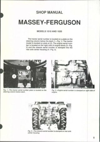
1. SHOP MANUAL
MASSEY-FERGUSON
MODELS 1010 AND 1020
The tractor serial number is located on a plate on the
steering column below the dash (1—Fig. 1). The tractor
model is located on plate at (2). The engine serial num-
ber is located on the right side of engine block (3—Fig,
2) and the chassis serial number is stamped into the
rear axle center housing (4—Fig. 3).
Fig, I—The tractor serial number plate Is located on the Fig. 2—Englne serial number Is stamped on right side of
steering column below dash. engine.
Fig. 3—The chassis serial number Is stamped on rear axle
center housing.
2. INDEX (By Starting Paragraph)
Models
1010 and 1020
BRAKES
Adjust 144
R & R and Overhaul 145
CLUTCH
Adjustment 55
Clutch Shaft and Release Bearing 58
R & R and Overhaul 56
COOLING SYSTEM
Radiator 48
Thermostat 49
Water Pump 50
DIESEL FUEL SYSTEM
Fuel Filters and Lines 37
Glow Plugs 47
Governor and Injection Pump Camshaft . 41
Injector Nozzles 43
Injection Pump 39
ELECTRICAL SYSTEM
Alternator and Regulator 51
Circuit Description 54
Safety Switches 53
Starter 52
ENGINE AND COMPONENTS
Cam Followers 23
Camshaft 27
Connecting Rod and Bearings 31
Crankshaft and Main Bearings 32
Crankshaft Rear Oil Seal 33
Cylinder Head 18
Flywheel 34
Front End/Engine Split 16
Oil Pan 35
Oil Pump 36
Piston Pin 30
Piston, Rings and Cylinder 29
R & R Engine 17
Rocker Arms 22
Rod and Piston Units 28
Timing Gear Housing 25
Timing Gears 26
Valve Clearance 19
Valve Springs 21
Valve Timing 24
Valves, Guides and Seats 20
Models
1010 and 1020
FINALDRIVE AND AXLES 142
FRONT AXLE SYSTEM (FOUR-WHEEL
DRIVE)
Axle Housing, King Pin, Axle Shafts and
Universal Joints 13
Differential 15
Front Axle Assembly H
Front Axle Assembly and Steering Linkage 10
Front Final Drive 12
FRONT AXLE SYSTEM (TWO-WHEEL
DRIVE) 1
HYDRAULIC LIFT SYSTEM
Control Valve 170
Fluid and Filters 163
Hydraulic Pump 164
Lift Cover 168
Relief Valve
1010 Hydro and All 1020 Models 167
1010 Standard Models 166
POWER TAKE-OFF i
Front Pto 161^
MidPto 158
Rear Pto
1010 Hydro Models 147
1010 Standard Models 146
1020 Hydro Models 153
1020 Standard Models 152
REAR AXLE CENTER HOUSING AND
DIFFERENTIAL
Axle Center Housing
1010 Hydro Models 122
1010 Standard Models 120
1020 Hydro Models 126
1020 Standard Models 124
Differential and Bevel Gears
1010 Hydro Models 132
1010 Standard Models 128
1020 Hydro Models 139
1020 Standard Models 136
STEERING SYSTEM
Power Assist 8
Steering Gear 6
TRANSMISSION
1010 HYDRO
Front-Wheel-Drive Idler 84
Hydrostatic Unit 76
3. Models
1010 and 1020
TRANSMISSION
1010 HYDRO (Cont.)
Lubrication 69
Overhaul 78
Range Transmission 80
Spacer Housing Assembly 79
Tests and Adjustments 71
Troubleshooting 70
TRANSMISSION
1010 STANDARD
Inspection 59
Lubrication 60
Overhaul 62
Remove and Reinstall 61
TRANSMISSION
1020 HYDRO
Front-Drive Output Shaft 118
Models
1010 and 1020
TRANSMISSION
1020 HYDRO (Cont.)
Hydrostatic Unit 109
Lubrication 102
Overhaul , 111
Range Transmission 113
Spacer 112
Tests and Adjustments 104
Troubleshooting 103
TRANSMISSION
1020 STANDARD
Creeper (Mode) Transmission 97
Front-Wheel Drive 100
Inspection. 86
Lubrication 87
Main and Range Transmission 89
Shifter Cover 88
DUAL DIMENSIONS
This service manual provides specifications in both U.S. Customary and Metric (SI) systems of
measurement. The first specification is given in the measuring system perceived by us to be the
preferred system when servicing a particular component, while the second specification (given in
parenthesis) is the converted measurement. For instance, a specification of 0.011 inch (0.28 mm)
would indicate that we feel the preferred measurement in this instance is the U.S. Customary system
of measurement and the Metric equivalent of 0.011 inch is 0.28 mm.
CONDENSED SERVICE DATA
1010 standard
Models
1010 Hydro 1020 Standard 1020 Hydro
GENERAL
Engine Make
Model
Number of Cylinders.
Bore
Stroke
Displacement
Hinomoto -
CS86 • -CS112-
— 70 mm —
(2.756 in.)
— 75 mm —
(2.953 in.)
865 cc
(52.8 cu. in.)
— 75 mm —
(2.953 in.)
— 85 mm —
(3.347 in.)
— 1126 cc —
(68.7 cu. in.)
4. CONDENSED SERVICE DATA (Cont.)
Models
1010 Standard 1010 Hydro 1020 Standard 1020 Hydro i
GENERAL (Cont.)
Compression Ratio " 23:1 —
Firing Order ~" 1-3-2 —
Valve Clearance (Cold) -
Inlet ' —0.30 mm ——
(0.012 in.)
Exhaust —0.35 mm
(0.014 in.)
Valve Face and Seat Angle -
Inlet and Exhaust ^ — 45°—
Injection Timing - BTDC
Static 25° - —
Fuel Pump
Make — Diesel Kiki —
Engine Low Idle, rpm ' 850-900 -
Engine High Idle, rpm 2650-2700 2650-2700 2500-2550 2650-2700
Engine Rated Speed, rpm 2500 2500 2350 2500
Battery Terminal Grounded Negative
Transmission, Speeds 3F-1R x 2 Hydrostatic 3F-1R x 2 x 2 Hydrostatic
Variable x 2 Variable x 3
SIZES
Crankshaft Main Journal Diameter • 59.960-59.985 mm
(2.3606-2.3614 in.)
Crankshaft Crankpin Diameter . . . 47.960-46.980 mm
(1.8882-1.8890 in.)
Camshaft Journal Diameter -
Front 45.910-45.925 mm
(1.8075-1.8081 in.)
Piston Pin Diameter 23.990-23.996 mm 24.989-24.999 mm
(0.9445-0.9447 in.) (0.9839-0.9841 in.)
Valve Stem Diameter -
Inlet 7.945-7.960 mm 7.945-7.960 mm
(0.3128-0.3134 in.) (0.3128-0.3134 in.)
Exhaust 7.920-9.935 mm 7.910-9.925 mm
(0.3118-0.3124 in.) (0.3114-0.3120 in.)
CLEARANCES
Main Bearing Diametral Clearance —^0.03-0,095 mm
(0.0012-0.0037 in.)
Rod Bearing Diametral Clearance . — 0.03-0.095 mm
(0.0012-0.0037 in.)
Camshaft Bearing
Diametral Clearance 0.021-0.092 mm
(0.0008-0.0036 in.)
Crankshaft End Play — 0.1-0.3 mm
(0.0039-0.0118 in.)
Piston Skirt to
Cylinder Clearance 0.07-0.109 mm
(0.0027-0.0043 in.)
CAPACITIES
Coohng System 3.0 L 4.0 L
(3.17 qt.) (4.4 qt.)
8
5. CONDENSED SERVICE DATA (Cont.)
Models
1010 Standard 1010 Hydro 1020 Standard 1020 Hydro
CAPACITIES (Cont.)
Crankcase With Filter 2.5 L* 3.0 L 3.7 L
(2.64 qt.*) (3.2 qt.) (4.0 qt.)
Transmission 17 L 23 L 26 L
(4.5 gal.) (6.08 gal.) (6.9 gal.)
Front Drive Axle Hubs
(Each Side) — 0.4 L
(0.42 qt.)
Front Drive Axle Housing 1,5 L
(1.6 qt.)
* Later models with two drain plugs - 3.0 L (3.2 qt.).
9
6. Paragraphs 1-3 MASSEY-FERGUSON
FRONT AXLE SYSTEM
(TWO-WHEEL DRIVE)
FRONT AXLE ASSEMBLY AND
STEERING LINKAGE
Two-Wheel-Drive Models
1. WHEELS AND BEARINGS. Front wheel bear-
ings should be removed, cleaned, inspected and re-
newed or repacked every 400 hours of operation. To
remove front wheel hub and bearings, raise and sup-
port the front axle extension, then unbolt and remove
the tire and wheel assembly. Remove cap (8—Fig. 4
or Fig. 5), cotter pin, castellated nut (10), washer and
cone of outer bearing (12). Slide the hub assembly
from spindle axle shaft. Remove seal (15) and cone for
inner bearing (14). Drive cups for bearings (12 and
14) from hub if renewal is required. Inner seal (9) can
be removed from spindle (16) if renewal is required.
Pack wheel bearings liberally with a suitable wheel
bearing grease. Reassemble by reversing disassem-
bly procedure. Tighten castellated nut (10) to a torque
Fig. 4—Exploded view of axle
wheel-drive 1010 models.
and wheel hub of two-
1. Screw
2. Axle pivot pin
3. Shims
4. Bushings
5. Axle main member
6. Grease fitting
8. Bearing cap
9. Inner seal
10. Castellated nut
11. Washer
12. Outer hearing
13. Wheel huh
14. Inner hearing
15. Seal
16. Spindle
17. Seal
18. Thrust bearing
19. Bushing
20. Bushing
21. Key
22. Left steering arm
23. Right steering arm
of 29.4 N.m (22 ft.-lbs.), loosen nut, then tighten nut
to 9.8-14.7 N.m (7.2-11.0 ft.-lbs.) torque and install
new cotter pin. Be sure to install cap (8), using new
gasket or sealer, and tighten retaining screws se-
curely. Bolts attaching front wheel to hub should be
tightened to 88 N.m (65 ft.-lbs.) torque.
2. TIE ROD AND TOE-IN. A single tie rod t on-
nects the left and right steering arms (22 and 23—
Fig. 4 or Fig. 5) which are attached to the steering
spindles (16). The automotive type tie rod ends are
not adjustable for wear and should be renewed if
worn. Rod end threaded into right end of tie rod is
used to adjust the distance between ends to establish
front wheel toe-in. Recommended toe-in is 3-10 mm
(V8-% in.) and should be measured between the wheel
rims on centerline of axle, parallel to ground. Roi ate
wheels and re-measure to be sure that wheels are not
bent, giving incorrect reading. Tighten rod end jam
nut after toe-in is correctly set.
3. SPINDLES, AXLE EXTENSIONS AND
BUSHINGS. To remove spindle (16—Fig. 4 or Fig. |
5), first remove the wheel and hub. Disconnect rod
end from steering arm (22 or 23), remove clamp screw
from steering arm, then remove steering arm. Re-
move key (21) and seal (if used) from top of spindle,
then lower spindle out of axle (5). Clean and inspect
Flg^ 5—Exploded view of front axie used on two-wheel-
drlve 1020 models. Refer to Fig. 4 for legend except shield
10
7. MODELS 1010 & 1020 Paragraphs 4-5
parts for wear or other damage and renew as neces-
sary.
Spindle bushings (19 and 20) should not require
reaming after pressing into position in axle (5). Be
sure that hole in spindle for grease fitting is clean and
open before assembling.
When reassembling, install thrust bearing (18) so
that numbered side of bearing is facing upward. In-
stall seal (17) and insert spindle through axle. Install
upper seal (if so equipped) and key (21), then locate
steering arm on top of spindle. Tighten steering arm
retaining clamp screw to 88 N.m (65 ft.-lbs.) torque.
Bolts attaching front wheel to hub should be tight-
ened to 88 N.m (65 ft.-lbs.) torque. Balance of reas-
sembly is the reverse of disassembly. Refer to
paragraph 2 for toe-in adjustment.
4. AXLE CENTER MEMBER, PIVOT PIN AND
BUSHINGS. To remove front axle assembly, first
remove any front mounted equipment, guards,
weights and weight frame. Raise front of tractor in
such a way that it will not interfere with the removal
of the axle. Remove the front wheels. Disconnect
steering hoses if equipped with power steering and
cover openings to prevent the entry of dirt. On all
models, disconnect drag link from right steering arm.
Support the axle with a suitable jack to prevent
tipping while permitting the axle to be lowered and
|moved safely. Remove axle pivot pin (2—Fig. 4 or Fig.
r5), carefully lower the axle assembly and roll axle
from under tractor.
Check axle pivot bushings (4) and renew if neces-
sary. Bushings are pressed into bore of axle and
should be installed flush with bore. Split in bushing
should be 45° from top of axle bore. It should not be
necessary to ream bushings after installation.
Reverse removal procedure when assembling. Axle
end play should be 0-0.3 mm (0-0.012 in.) for 1010
models; 0-0.4 mm (0-0.016 in.) for 1020 models. Push
the axle toward rear on pivot pin, then measure axle
end play with a feeler gauge. Shims (3) are available
in various thicknesses for adjusting end play. Make
sure that pin retaining screw (1) at front is tight and
that pin retaining nut at rear is snug, but not over-
tightened. Install cotter pin through pin and castel-
lated nut. Refer to paragraphs 2 and 3 for additional
torque values and assembly notes.
5. FRONT SUPPORT, The front axle and radiator
must be removed before unbolting the front axle
support from engine. The front axle, the front support
and the remainder of the tractor must each be sup-
ported separately while removing, while separated
and while assembling. Be sure that sufficient equip-
ment is available before beginning.
Remove any front mounted equipment, guards,
weights and weight frame. Unplug lights, then re-
move hood and grille assembly. Remove the battery,
drain cooling system, disconnect radiator hoses and
remove radiator assembly. Refer to paragraph 4 and
remove axle assembly. Remove the front pto, if so
equipped. On all models, attach a hoist or other
supporting device to front support, then remove the
five retaining screws from each side and separate the
front support from engine.
Reattach front support to engine by reversing the
removal procedure. Apply "Loctite 271" or equivalent
to the ten screws attaching front support and frame
to sides of engine. Complete assembly by reversing
the removal procedure.
8. Paragraphs 6-8 MASSEY-FERGUSON
STEERING SYSTEM
STEERING GEAR
All Models
6. A cross section drawing of the manual steering
gear assembly is shown in Fig 6. Note that the steer-
ing gears are contained within a cavity in the top of
the clutch housing and that the steering shaft ex-
tends through the clutch housing. The steering ratio
is 10:1 for all 1010 models and 13:1 for all 1020
models. Some differences will be noticed, including
the number of teeth on gears (12 and 15—Fig, 7) and
shaft (17) may be straight on some models.
7. R&R AND OVERHAUL. To service steering
gear, it is necessary to remove the steering wheel,
instrument panel cover and fuel tank. Disconnect
brake and clutch rods from pedals and pedal cross
Fig. &^Cross section drawing of steering gear typicai of
ali modeis. Refer to Fig. 7 for exploded view.
shaft, then unbolt and remove the steering wheel
shaft support (24—Fig. 7). Remove clamp rings- (7)
and slide boot (8) up to uncover universal joint. Re-
move lower retaining ring (4) and use a punch to d rive
lower pin (6) from universal joint, then separate
universal joint (5) from pinion shaft (12). Notice that
pins (6) are stepped and must be removed toward
larger end. Remove screws attaching cover (9) to
transmission housing, then remove cover, leaving
pinion shaft (12) in transmission housing. Pinion
shaft (12) and quadrant gear (15) can be removed
together after removing retaining nut (14). Steering
arm shaft (17) can be removed after splitting tractor
between engine and clutch housing, then removing
the engine clutch shaft.
When reassembling, front wheels must be straight
ahead and steering pinion (12) must be in center of
teeth on quadrant gear (15). Tighten nut (14) to 59-78
N.m (43-58 ft.-lbs.) torque. If tab lockwasher is in-
stalled under nut (14), flat side of nut should be
toward top and tab of washer should be bent up to
lock retaining nut. Some models may be equij^ped
with self-locking nut or two special nuts. Fill gear
cavity half full with multi-purpose lithium ])ase
grease. Nut for clamp bolt (22) retaining steering arm
(21) to lower end of shaft should be tightened to 78-90
N.m (57-68 ft.-lbs.) torque. The steering arm (21) o
some models is retained with a nut threaded to shaft
similar to the type (14) at upper end. The larger
retaining nut should be tightened to 98-117 N.m
(72-87 ft.-lbs.) torque.
POWER ASSIST
Models So Equipped
8. Power assisted steering is available and may be
installed on any model. Refer to Fig. 8 for view of flow
divider valve (1), steering valve and steering assist
cyhnder assembly (3), connecting hydraulic lines and
attaching brackets. Most service will consist of re-
moval, disassembly, cleaning and reassembly using
new seals. Refer to Fig. 9 for exploded view of cylinder
and valve unit.
To remove the power steering unit, raise front of
tractor so that weight is removed from the lront
wheels. Disconnect hydraulic lines (2 and 8—Fig. 8),
then tum steering wheel from lock to lock to dis-
charge oil from steering cylinder. Disconnect steering
unit from anchor bracket (4), steering arm (5) and
drag link (7).
To renew steering cylinder seals, remove ball joint |
end from cylinder rod (41—Fig. 9). Flatten the locking
groove on the cylinder, then unscrew cap and bearing
assembly (43) from cylinder (36). Withdraw cylinder
12
9. MODELS 1010 & 1020 Paragraph 8 (Cont.)
Fig. 7^Expioded view of dutch housing and
typicai steering gear.
1. Steering wheel
2. Bushing
3. Steering shaft
4. Retaining rings
5. Universal joint
6. Pins
7. Clamp rings
8. Boot
9. Steering gear cover
10. Oil seal
11. Snap ring
12. Steering pinion
13. Bearing
14. Retaining nut
15. Quadrant gear
16. Bearing
17. Steering arm shaft
18. Bearings
19. Snap ring
20. Key
21. Steering arm
22. Clamp bolt
24. Steering wheel
shaft support
22'
Fig. 8—Power assist (booster) steering is
instaiied on some models. Refer to Fig. 9
for expioded view of cyiinder and vaive
unit.
1. Flow divider
2. Pressure lines
3. Cylinder and
valve unit
4. Bracket
I
5. Steering arm (4WD)
6. Steering arm (2WD)
7. Drag link
8. Return lines
13
10. Paragraph 8 (Cont.) MASSEY-FERGUSON
IS
14
26
Fig. 9-~Explod0d view of steering BBSist cylinder and valve unit,
11. AcUuster 20. Dust cover 29. Spool rod
12. "O" ring 21. Plug 30. "0" ring
13. Spring 22. Washer 31. Seal ring
14. Valve plunger 23. "O" ring 32. Plug
15. Seat 24. Valve housing 33. Dust cover
16. "O" ring 25. Pin 34. Nut
17. Orifice 26. Valve spool 35. Yoke
18. "O" ring 27. Spring seat 36. Cylinder
19. "O" ring 28. Spring 37. Nut
38. Seal ring
39. "O" ring
40. Piston i
41. Rod I
42. "O" ring ^
43. Cap & bearing
44. Oil seal
45. Dust seal
46. Snap ring
rod, cap and piston (40) from cylinder. Slide the cap
off the rod. Remove retaining ring (46), then drive
dust seal (45) and oil seal (44) from the cap. Remove
seal ring (38) and "O" ring (39) from piston. Unbolt
and remove cylinder (36) from valve housing (24) if
renewal of "O" ring (18) is necessary. When installing
new seals note that lip of oil seal (44) faces inward
and lip of dust seal (45) faces outward.
After installing power steering unit on the tractor,
start the engine and tum steering wheel from lock to
lock several times to bleed air from the cylinder and
lines.
14
11. MODELS 1010 & 1020 Paragraphs 9-12
FRONT AXLE SYSTEM
(FOUR-WHEEL DRIVE)
9. A mechanical front-wheel drive is available on
these models. There are some differences between the
front-wheel-drive systems used on these models that
will be referred to in the servicing instructions which
follow.
FRONT AXLE ASSEMBLY AND
STEERING LINKAGE
Four-Wheel-Drive Models
10. TIE ROD AND TOE-IN. A single tie rod con-
nects the left and right king pin housings. The auto-
motive type tie rod ends are not adjustable for wear
and should be renewed if worn. Rod end threaded into
right end of tie rod is used to adjust the distance
between ends to establish front wheel alignment.
Recommended alignment is when wheels toe-in less
than 5 mm (^/IQ in.) or toe-out no more than 5 mm
(3/l6 in.). To check alignment, measure between the
wheel rims on centerline of axle, parallel to ground.
Rotate wheels and re-measure to be sure that wheels
are not bent, giving incorrect reading. Tighten tie rod
I end jam nut after wheel alignment is correctly set.
FRONT AXLE ASSEMBLY
Four-Wheel-Drive Models
11. REMOVE AND REINSTALL. The front axle
assembly includes the differential and axle pivot,
drive shaft, axle housings, and final drive. Refer to
Fig. la^The differential must be lowered 10 mm (3/8 In.)
by loosening screws (S) to have enough clearance to
remove axle housing from modeis with standard trans-
missions. Screws may come out and differentiai may fall
if standard screws are ioosened more than 15 mm (9/16
in.). Frontpivot bracicet is retained in front support by four
screws entering from the side (F).
appropriate paragraphs for disassembly and service
to individual units.
To remove the complete front drive axle assembly,
first support tractor behind axle and remove both
front wheels. Disconnect drag link from steering arm
and, if unit is to be disassembled, drain oil from final
drive and differential housings. Loosen clamp from
drive shaft cover and slide front half of cover toward
rear. Remove the three screws attaching rear of drive
shaft cover to rear housing, lift snap rings from
grooves in drive shaft and relocate snap rings toward
center of drive shaft. Move drive shaft couplings
toward center of drive shaft, then remove drive shaft
and cover. Support axle level with floor to prevent
tipping, then remove the two screws (S—Fig. 10)
attaching rear pivot bracket and the four screws
attaching the front pivot bracket. Carefully lower the
front axle assembly and pivot brackets away from
front support frame.
When installing, be sure that ring gear is on correct
side of tractor (pinion) and that differential drain
plug is toward bottom. Be sure to install new "0"
rings around differential pivots against pivot brack-
ets. Shims are available to limit clearance of differ-
ential between pivot brackets to 0.2 mm (0.008 in.).
Tighten pivot bracket retaining screws to 88 N.m (65
ft.-lbs.) torque. Remainder of installation is reverse
of removal procedure. Tighten wheel retaining nuts
to 87 N.m (64 ft.-lbs.) torque. ,
FRONT FINAL DRIVE
Four-Wheel-Drive Models
12. R&R AND OVERHAUL. Each front final
drive can be disassembled without disturbing other
parts of the drive system. Support weight of tractor
front end and remove front wheel. Remove drain plug
(13—Fig. 11), then unbolt cover (3) from housing (15).
Carefully bump cover from studs and bearing (6) from
inner bore, then withdraw cover, stub axle, and re-
duction gear from housing. Remove cotter pin then
remove nut (8) and washer (7) from inner end of stub
axle (1). Bump inner end of axle with a soft hammer
while supporting cover (3) to remove bearing (6), gear
(5), bearing (4) and cover (3) from axle (1). Oil seal (2)
and bearings (4 and 9) can be removed from cover if
renewal is required. Drive gear (11) can be removed
from 1010 models after removing snap ring (10).
Outer collar (42) must be removed before removing
pinion and shaft (41) from 1020 models.
Be sure that inner part of seal (2) is removed from
stub axle (1) and outer part ofseal (2) is removed from
12. Paragraph 12 (Cont.) MASSEY-FERGUSON
29s
29
Fig ii—jExpioded view of front-wheel-drlve housing and related parts used on 1010 models,
shaft and universal joint parts (41-45) used on 1020 models.
1
2
3
3G
4
5
Axle
Oil seal
Cover
Gasket
Bearing
Gear
6. Bearing
7. Washer
Nut
Bearing
Snap ring
Gear
Bearing
13. Drain plug
14. Fill plug
15. King pin housing
16. "O" ring
17. Bearing race
18. Bearing balls
(89 each race)
19. Bearing race
20. Seal
21. Universal joint
& pinion shaft
22. Housing
23. Bushing
24. Bearing
25. Seal
26. Adjusting screw
27. Nut
28. Steering arm
29. Support
29S. Stop screw
30. Bearing
31. Drive shaft
32. "O" ring
33. Thrust washer
Inset shows different drive
34. Differential housing
35. Ring sleeve
36. Lower arm pin
37. Lower support arm
38. Dust seal
39. Bushing
40. Oil seal
41. Pinion gear
and shaft
42. Bearing collar
43. Constant velocit} joint
44. Spacer
45. Drive shaft
cover (3). Pack grease between lip of oil seal before
installing and coat axle shaft seal surface with oil
before inserting into seal. Install gear (5) so that
protruding boss is toward inside. Install washer (7)
and tighten nut (8) to 78 N.m (58 ft.-lbs.) torque, then
install cotter pin. DO NOT loosen nut to install cotter
pin. Make sure all gasket surfaces are clean andj
install gasket (3G). Tighten fasteners attaching cover
(3) to 27 N.m (20 ft.-lbs.) torque. Tighten wheel re-
taining nuts to 87 N.m (64 ft.-lbs.) torque. Each gear
16
13. MODELS 1010 & 1020
housing should contain approximately 0.4 L (0.42 qt.)
of "Massey-Ferguson Permatran III," SAE 80 GL-3,
SAE 80 GL-4 oil or equivalent. Fill through opening
for plug (14).
AXLE HOUSING, KING PIN,
AXLE SHAFTS AND
UNIVERSAL JOINTS
Four-Wheel-Drive Models
13. REMOVE AND REINSTALL. The differen-
tial housing can remain installed on tractor while
removing and installing axle housing. To remove one
axle housing and associated parts from one side, raise
tractor and remove wheel. Remove drain plug (13—
Fig. 11) and allow oil to drain. Support the axle that
will remain installed so that the axle to be removed
is lower. On models with standard transmission (not
Hydro models), it is also necessary to lower the dif-
ferential housing for additional clearance. Refer to
paragraph 11 to remove Front Final Drive if so de-
sired. The king pin housing (15) can be removed if
desired, leaving housing (22) attached to differential
housing (34).
To remove, detach tie rod, drag link and any other
interfering connections. On models with standard
transmission (not Hydro models), it is necessary to
loosen drive shaft cover and lower the differential
housing 10 mm (^/g in.). Remove the three screws
attaching drive shaft cover to rear housing, then
loosen (but do not remove) the two screws (S—Fig.
10) attaching axle rear carrier (pivot bracket) to the
front support, which will allow differential to lower
the correct amount. If screws are loosened too much,
screws will come out and differential will fall. If not
loosened, there will not be enough room to remove
axle housing. On all models, support axle housing
safely, then unbolt housing from differential housing
(34—Fig. 11). Carefully move the axle (31) and hous-
ing (22) away from differential and from under trac-
tor.
NOTE: The screws and stud nuts attaching axle
housing to one side of differentiai housing aiso
attach the differentiai housing cover. Be careful to
separate between axie housing and cover. The
cover is located between ieft axie housing and left
side of differential housing on 1010 Hydro modeis.
Cover is iocated between right axie housing and
right side of differentiai housing of other 1010 and
1020 models. Cover should stay with differential
housing and does not need to be removed; however,
reinstail using a new seaiing "O" ring, if cover is
removed.
Carefully slide axle shaft (31—Fig. 11) out together
with housing (22) unless king pin is to be disassem-
bled. If axle (31) pulls out of bearing (30), it may be
Paragraphs 13-14
necessary to remove king pin housing (15) so that
shaft (31 or 45) can be installed in bearing (30) and
universal joint (21 or 43) can be installed on end of
shaft (31 or 45).
To reinstall, be sure that opposite axle is raised to
permit more room on side to be installed. Install new
"O" ring (32) on differential housing, be sure that
thrust washer (33) is positioned on axle shaft (31 or
45), then carefully slide axle assembly onto differen-
tial housing. Coat threads of screws and stud nuts
attaching axle housing to differential housing with
"Loctite 271" or equivalent, then tighten to 55 N-m
(41ft.-lbs.) torque. Tighten screws attaching differen-
tial pivot brackets (S—Fig. 10) to 88 N.m (65 ft.-lbs.)
torque. Tighten wheel retaining nuts to 87 N.m (64
ft.-lbs.) torque. Each outer final drive gear housing
should contain approximately 0,4 L (0.42 qt.) of
"Massey-Ferguson Permatran III," SAE 80 GL-3,
SAE 80 GL-4 oil or equivalent. Fill through opening
for plug (14). The axle housings and differential hous-
ing contain approximately 1.5 L (1.6 qt.) of the same
fiuid and are filled through opening for plug (F).
14. OVERHAUL. Service to king pins, bearings
and universal joints can be accomplished without
separating axle housing from differential housing;
however, removal is required for service to bearing
(30—Fig. 11) and axle shaft (31 or 45).
Refer to paragraph 12 and remove the front final
drive (1 through 9). On 1010 models, gear (11) can
also be removed after removing snap ring (10). On all
models, detach tie rod and drag link, then loosen or
remove locknut (27) and make sure that adjusting
screw (26) is free to turn. Unbolt upper support (29)
from king pin housing (15) and carefully remove
upper support from dowels. Lower support (37)
should hold king pin housing in place. If necessary,
clean and lubricate threads of adjusting screw (26) to
facilitate adjustment while reassembling. Support
king pin housing (15) and remove the three screws
attaching lower support (37) to axle housing (22).
Lower king pin housing and related parts away from
axle housing and make sure that all 89 bearing balls
(18) are located. The 5.5563 mm (0.219 in.) diameter
bearing balls can cause extensive damage if caught
between gear teeth or left out. Seal (20), bearing races
(17 and 19), balls (18), "O" ring (16) and ring sleeve
(35) should be renewed when disassembled if at all
questionable.
Clean all parts thoroughly and make sure that all
89 bearing balls (18) are accounted for. Carefully
press upper race (19) and seal (20) in axle housing
and pack lip of seal with grease. Coat inner race (17)
with grease and carefully stick all 89 loose bearing
balls to the race with the grease. Position inner race
with bearing balls into the installed upper outer race
and make sure that it is held firmly in place. The seal
wear ring (35) should be bonded to the lower (king
pin) housing (15) with "Loctite 277" or equivalent. All
17
14. Paragraph 15
old adhesive must be removed and surface should be
free of scratches, dirt and oil. Apply adhesive evenly
only when ready to assemble king pin housing to axle
housing, because it begins to cure in five minutes.
Adhesive will stabilize after about 24 hours.
Lubricate adjusting screw (26) and lip of seal (25)
with grease. Make sure that adjusting screw is free
to turn easily Install bearing (30) with sealed side
toward outside (universal joint side). Position "O"
ring (16) in groove of housing (15) and bearing (12) in
bore of housing. On 1020 models, install pinion gear
and shaft (41) and constant velocity universal joint
(43). On 1010 models, install universal joint (21)
through bearing (12), then install gear (11) and snap
ring (10). On all models, position shaft (31 or 45) in
bearing (30), then locate king pin housing (15) against
axle housing (22) with splines ofuniversal joint mesh-
ing with splines of shaft (31 or 45). Hold axle housing
and king pin housing in proper position, then install
support (29). Make sure that adjusting screw is not
binding and tighten support retaining screws to 70
N.m (51 ft.-lbs.) torque. After support retaining
screws are properly tightened, loosen adjusting screw
(26) to make sure that screw is not binding, then
tighten to 9.8 N.m (7.2 ft.-lbs.) torque and install
locknut (27). Install lower support arm (37) after
upper support is installed and adjusted. Refer to
MASSEY-FERGUSON
paragraph 13 for attaching axle housing to diffen;n-
tial housing and to paragraph 12 for installing final
reduction gears and cover.
DIFFERENTIAL
Four-Wheel-Drive Models
15. R&R AND OVERHAUL. Refer to paragraph
11 and remove both axles and differential as an
assembly, then refer to paragraph 13 and separate
the axle housings from the differential housing. Refer
to Fig. 12 and bump bearings (23), differential carrier
(31), ring gear (24) and side cover (33) out of housing
(18). Be careful not to mix, damage or lose shims (22L
and 22R) behind both bearings (23).
The pinion nut (10) is staked in position and is
secured with "Loctite." Hold pinion shaft and remove
nut (10). Be careful to notice position of shims (15 and
15M) between bearings (13) and behind teeth of pin-
ion gear (17). Shims (15) adjust preload of bearings
(13), and shims (15M) control mesh position of pinion
(17). Bump pinion (17) inward to remove. Drive pin
(25) out, then remove shaft (26) and parts (27, 28, 29
and 30). Bearings (13), spacer (16), seal collar (12),
seal (11) and associated parts can be removed for
inspection or renewal.
14
Fig^ 12—Exploded view of front axle differential
and drive shaft for 1020 Hydro tractor. Other
models are simitar, but differences will be noted.
Screw (S) and location for one of the screws (F)
are also Indicated In Fig. 10.
1. Coupling
2. Clamp
3. Housing
4. Drive shafl
5. "O" rings
6. Pivot bracket
7. Grease fittings
8. Bushing
9. "O" rings
10. Retaining nut
11. Oil seal
12. Seal collar
13. Bearing
14. Snap rings
15. Shim
15M. Shim
16. Spacer
17. Pinion gear
18. Housing
19. Drain plug
20. Shim
21. Front pivot bracket
22L. Shims
22R. Shims
23. Bearings
24. Ring gear
25. Pin
26. Shaa
27. Thrust washer
28. Pinions
29. Side gears
30. Thrust washer
31. Differential carrier
32. "O" ring
33. Cover
18
15. MODELS 1010 & 1020 Paragraph 15 (Cont.)
Ring Gear
Bevel Pinion
Fig. 13—Cross section of typical front drive differentiai
assembiy.
Fig. 14—Check gear backlash using a diai indicator (D)
positioned as shown.
NOTE: On 1010 Hydro tractors, the ring gear (24)
and cover (33) are located on left side of pinion. The
ring gear and cover of all other models are located
on the right as shown in Fig. 12 and Fig. 13,
Observe the following when assembling differen-
tial on all models. Ring gear (24—Fig. 12)) and pinion
(17) are available only as a matched set. Threads of
screws which attach ring gear (24) to carrier (31)
should be coated with "Loctite 271" or equivalent
before tightening to 50 N.m (37 ft.-lbs.) torque.
Assemble pinion (17) and associated parts (12
through 16) in housing (18) using shims (15) that
were removed. Seal (11) should be omitted when
checking bearing adjustment and gear mesh and
should only be installed upon fmal assembly. Tighten
nut (10) to 59-79 N.m (44-58 ft.-lbs.) torque, then
check torque required to turn pinion shaft in bearings
(13). If rolling torque is not within range of 0.59-0.98
N.m (5.2-8.6 in.-lbs.), add or decrease thickness of
shims (15) between bearings (13) as required. Re-
check rolling torque after changing shims and tight-
Fig. 15—Determine correct total thickness of shims by
measuring clearance with feeler gauge (F) as shown.
ening nut (10) to 59-79 N.m (44-58 ft.-lbs.) torque.
Shims (15M) between pinion gear and front bearing
are the same as shims (15); however, shims at location
(15M) adjust gear mesh position.
Press carrier bearings (23) firmly onto differential
carrier (31), then install carrier and bearing assembly
into differential housing using shims (22L) that were
originally installed. Make sure that inner bearing is
firmly seated against shims in housing (18), then
check backlash between pinion and ring gear with a
dial indicator mounted as shown in Fig. 14. Correct
backlash is 0.13-0.18 mm (0.005-0.007 in.). Backlash
is increased by adding shims (22L) between inner
bearing (23) and housing (18). Install cover (33) using
at least three evenly spaced screws, omitting "0" ring
(32). Flat washers will be necessary if original long
screws are used to hold cover on while checking.
Tighten cover retaining screws, then measure clear-
ance between bearing outer race and bore in cover as
shown in Fig. 15. Remove cover (33—Fig. 12) and
install shims (22R) equal to the clearance measured
(Fig. 15). Shims (22L and 22R—Fig. 12) are alike.
Mesh position of pinion and ring gear can be
checked using appropriate die or red lead on gear
teeth. Typical gear mesh patterns are shown in Fig.
16. Shims (15M—Fig. 12) are the same as shims (15);
however, shims at location (15M) adjust gear mesh
position and shims at (15) adjust bearings (13). Mesh
pattern (B—Fig. 16) indicates that ring gear is too far
away from pinion and can usually be corrected by
moving shims (22L—Fig. 12) from inside housing (18)
to location (22R) in cover. Mesh pattern (C—Fig. 16)
is caused by too little backlash (ring gear too close to
pinion). Condition (C) can be corrected by moving
shims (22R—Fig. 12) from cover (33) to location (22L)
in housing (18). Mesh pattern (D—Fig. 16) is caused
19
16. Paragraphs 16-17 MASSEY-FERGUSON
Fig. 16—Correct mesh position of pinion
and ring gear will be Indicated by a pattern
centered on gear teeth as shown at (A).
Refer to text for corrective action if mesh is
not as shown at (A).
by pinion (17—Fig. 12) too far from center ofring gear
and is corrected by adding shims at (15M). Mesh
pattern (E—Fig. 16) is caused by ring gear too far into
ring gear and can be corrected by removing some
shims (15M—Fig. 12). If mesh position of pinion is
changed by adding or removing shims (15M), it will
be necessary to recheck backlash and change posit ion
of shims at (22L and 22R).
ENGINE AND COMPONENTS
FRONT END/ENGINE SPLIT
All Models
16. To separate the front axle and support from
front of engine, remove any front mounted equip-
ment, guards, weights and weight frame. Unplug
lights, thread wires through retaining clips and lay
on top of engine, then remove hood and grille assem-
bly. Disconnect battery cables, drain cooling system,
disconnect radiator hoses and remove air cleaner
hose (if necessary). Disconnect steering drag link and
detach steering cylinder and hoses if equipped with
power assisted steering. Remove the front pto, if so
equipped. Remove the drive shaft from Hydro models
with four-wheel drive. Detach drive shaft cover from
other four-wheel-drive models and be prepared to
remove drive shaft and cover as the front assembly is
moved forward. On all models, wedge between axle
and front support frame to prevent tipping. Support
engine and rear of tractor securely and safely so that
front support and frame can be unbolted and re-
moved. Support the front axle, front support, battery
and radiator to prevent uncontrolled movement, then
remove the five screws that attach frame to each side
of engine. Carefully move the front axle, front sup-
port, battery and radiator assembly forward away
from engine.
Attach front support to engine by reversing the
removal procedure. Apply "Loctite 271" or equivalent
to the ten screws attaching front support and frame
to sides of engine. Complete assembly by reversing
the removal procedure.
R&R ENGINE
All Models
17. To remove the engine, first refer to paragraph
16 and split tractor between front support and fi ont
of engine. Be sure that rear wheels are blocked pi'op-
erly so that engine can be removed and reinstalled
safely. Disconnect wires from engine temperature
warning gauge sender, oil warning light switch, al ter-
nator, starting glow plugs and starter motor. Thread
wires through retaining clips and position out of the
way. Detach tachometer cable from drive on engine,
throttle rod from pump lever and engine stop cable
from pump stop lever. Shut fuel off at tank, disconnect
fuel lines f*rom pump and fuel filters, then remove the
fuel filter assembly from engine. Lower three-point
hitch, drain transmission, then remove hydraulic
pressure line between pump and hydraulic lift cover.
Remove hydraulic suction line from filter to hydraulic
pump. Cover all fuel system and hydraulic system
20
17. Thank you very much
for your reading.
Please Click Here
Then Get More
Information.