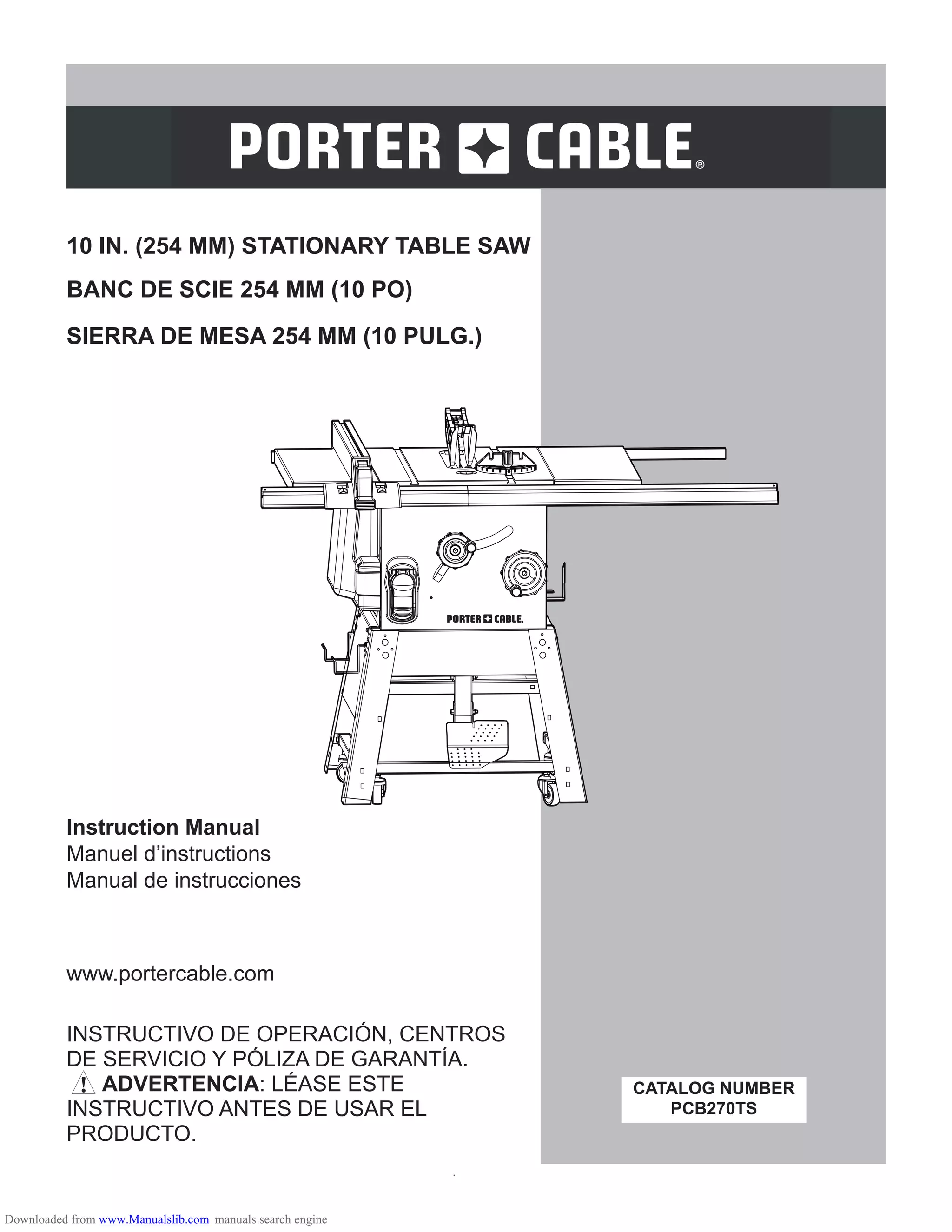
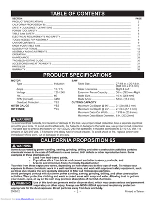
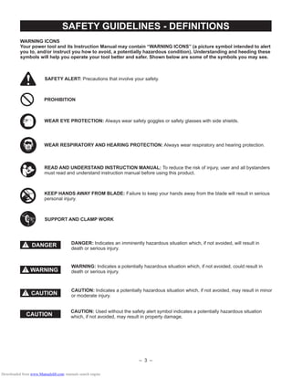
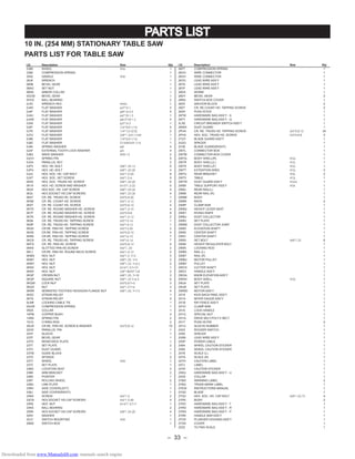
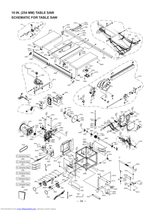
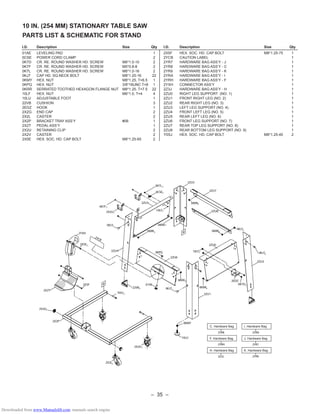
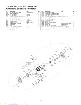
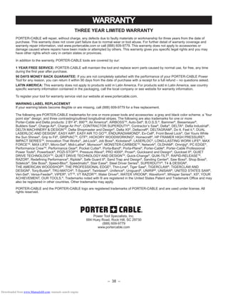
This document provides safety instructions and assembly instructions for a 10-inch stationary table saw. It begins with safety warnings and guidelines for power tool and table saw use. It then provides specifications for the saw such as its dimensions, voltage, blade size, and cutting capacities. The document continues with sections on assembly and adjustments, operation, maintenance, troubleshooting, accessories, parts lists, and warranty information for the saw.
JCB VIBROMAX 1105 SINGLE DRUM ROLLER Service Repair Manualjskemmsnnde
This is the Highly Detailed factory service repair manual for theJCB VIBROMAX 1105 SINGLE DRUM ROLLER, this Service Manual has detailed illustrations as well as step by step instructions,It is 100 percents complete and intact. they are specifically written for the do-it-yourself-er as well as the experienced mechanic.JCB VIBROMAX 1105 SINGLE DRUM ROLLER Service Repair Workshop Manual provides step-by-step instructions based on the complete dis-assembly of the machine. It is this level of detail, along with hundreds of photos and illustrations, that guide the reader through each service and repair procedure. Complete download comes in pdf format which can work under all PC based windows operating system and Mac also, All pages are printable. Using this repair manual is an inexpensive way to keep your vehicle working properly.
Service Repair Manual Covers:
General Information
Engine
Electrical
Hydraulic
Power Train
Parking Brake System
Vibration System
Steering System
Chassis
Attachments
File Format: PDF
Compatible: All Versions of Windows & Mac
Language: English
Requirements: Adobe PDF Reader
NO waiting, Buy from responsible seller and get INSTANT DOWNLOAD, Without wasting your hard-owned money on uncertainty or surprise! All pages are is great to haveJCB VIBROMAX 1105 SINGLE DRUM ROLLER Service Repair Workshop Manual.
Looking for some other Service Repair Manual,please check:
https://www.aservicemanualpdf.com/
Thanks for visiting!
8
Una forma de dirigir las operaciones con montacargas en puertos y otras areas, los accidentes en gruas horquillas no son menores, como tambien el cuidado del medio ambiente con la motorización de las gruas, material de apoyo a supervisores y operadores
Project Name: xxx
RA Ref No.: xxx
RA compilation Date: Review date:
Date:
Compiled by:
Reviewed by:
Approved by:
Overall Task Details
Hydrostatic pressure testing of pipework inside buildings Relevant Applicable MAS:
• Additional Training required:
NOC’s Required for task:
RISK SCORE CALCULATOR
Use the Risk Score Calculator to Determine the Level of Risk of each Hazard
What would be the
CONSEQUENCE
of an occurrence be? What is the LIKELIHOOD of an occurrence? Hierarchy of Controls
Frequent/Almost certain (5)
Continuous or will happen frequently Often (4)
6 to 12 times a year Likely (3)
1 to 5 times a year Possible (2)
Once every 5 years Rarely (1)
Less than once every 5 years Can the hazard be Eliminated or removed from the work place?
Catastrophic (5)
Multiple Fatalities High 25 High 20 High 15 Medium 10 Medium 5 Can the product or process be substituted for a less hazardous alternative?
Serious (4)
Class 1 single fatality High 20 High 16 High 12 Medium 8 Low 4 Can the hazard be engineered away with guards or barriers?
Moderate (3)
Class2 (AWI or LTI) or Class 1 Permanently disabling effects High 15 High 12 Medium 9 Medium 6 Low 3 Can Administration Controls be adopted
I.e. procedures, job rotation etc.
Minor (2)
Medical attention needed, no work restrictions. MTI Medium10 Medium 8 Medium 6 Low 4 Low 2 Can Personal Protective Equipment & Clothing be worn to safe guard against hazards?
Insignificant (1)
FAI Medium10 Medium 4 Low 3 Low 2 Low 1
No Specific Task Step
(In sequence of works) Hazard Details Consequence/Risk Initial Risk Rating Control Measures Residual Risks Additional Control Measures RR
L C RR
1 Pressure testing equipment • Use at high pressure; • Rupture/failure of pump during testing;
• Valve/connection failure;
• Instrument failure resulting in system over-pressurization;
3 3 9 MED i. The supervisor in charge of the test shall ensure that all pressure testing gauges etc. are in good sound condition, undamaged, correctly dated with the current valid calibration and that appropriate calibration certificates are available;
ii. All pumps shall be in sound condition and complete with a valid test certificate. Any vulnerable items such as manometers and pressure switches shall be removed or isolated from the system prior to testing if not required;
iii. The test supervisor shall carry out a thorough inspection of the system before requesting the permit detailed above to ensure that all isolations, blanks and other specified safety devices are in place before testing commences; No test documentation available Quarantine equipment until valid documentation provided Low
2 Permit to work system • Interaction of personnel and high pressure system; • Injury due to uncontrolled testing;
• Injury due to failure to ensure adequate pre-checks undertaken; 3 4 12 HIGH i. All pressure testing operations shall require a Permit to Work to ensure that no pressure testing will be allowed to commence until all,
Hoàn thiện công tác tuyển dụng và đào tạo nguồn nhân lực tại công ty Sao Nam Việt. Thời gian gần đây có rất nhiều nghiên cứu khác nhau về tuyển dụng và đào tạo nhân lực thuộc các khu vực, đơn vị ở tất cả các loại hình kinh doanh khác nhau. Điều này chứng tỏ công tác tuyển dụng và đào tạo nhân lực đang ngày càng được quan tâm, trở thành đề tài nóng hổi không chỉ trên các diễn đàn quản trị nhân lực và các tạp chí có tiếng mà còn được các tác giả đưa vào công trình nghiên cứu khoa học cấp bộ, cấp quốc gia hay trong cả bài luận án tiến sĩ.
http://sandblaster-parts.com/?gclid=CNSIx_2P-cQCFQSUfgodjxIAWA | Safety is critical in any field, but especially a key factor of importance for sandblasting jobs. Our presentations will teach you how to protect yourself from harm on the job.
Báo Cáo Thực Tập Quản Trị Kinh Doanh tại Công ty TNHH Deuck Woo Việt Nam
Tải tài liệu qua zalo 0936.885.877
dịch vụ làm báo cáo thực tập luanvantrithuc.com
Báo Cáo Thực Tập Quản Lý Tại Công Ty Bảo Hiểm, 9 Điểm. So sánh những kiến thức đã học và quy trình làm việc tại doanh nghiệp. Hiểu rõ về công ty, quá trình làm việc tại nơi thực tập. Tìm hiểu về bộ phận làm việc mong muốn tại một doanh nghiệp.
At Wilcox Door, we understand the importance of a fully-functioning, safe loading dock area. Through our installation, maintenance and quality products, we'll help keep your shipping/receiving areas operating efficiently. Accessories such as dock lights, bumpers, shelters and truck restraints are also available.
1. Project Information: (To be filled by initiator/originator)
Project Name: Permit No.:
Project Location:
Requesting Contractor/Company
2. Permit Issuance Details: (To be filled by initiator/originator)
THIS PERMIT IS ONLY FOR ONE SHIFT AND NOT EXTENDABLE
Description of Task:
Location, Grid Line & Floor / Level:
No of persons working :
Permit Validity:
Time (from): __________Hrs.
Time (To): __________Hrs.
Date:
3. Prerequisites: (To be filled by initiator/originator and verified by Evaluator)
Checks Yes-No-NA Checks Yes-No-NA
Method statement and Risk assessment developed, approved and communicated? ☐ ☐ ☐
Emergency response procedure and rescue plan are developed & communicated? ☐ ☐ ☐
Engage competent Scaffold erector and Carpenters for the de-shuttering task? ☐ ☐ ☐
All nails shall be removed from formwork materials upon dismantling or at least it shall be bent with hammer to avoid pricks? ☐ ☐ ☐
Pre-start briefing shall be done on daily basis before starting the work in each shift? ☐ ☐ ☐
Protruding steels shall be protected by rebar cap or fabricated wood cap. Immediately relocate dismantled materials from the activity area? ☐ ☐ ☐
Ensure de-shuttering area is illuminated with task light? ☐ ☐ ☐
Do not leave any struck formwork materials hanging in concrete (i.e. plywood, wood). Peel off the duct tape used to cover the plywood gaps ☐ ☐ ☐
Do not throw form work materials from top to ground level? ☐ ☐ ☐
Do housekeeping every one hour. Stack the stripped off materials according to its size and type separately away from access routes and pedestrian walk ways ☐ ☐ ☐
Ensure two men handle each form work material to bring down safely and stack them safely? ☐ ☐ ☐
Ensure the availability and use of Safety Helmet, Hand gloves, clear eye protection, Safety Harness and ear plug. ☐ ☐ ☐
Ensure safety harness is hooked to the scaffold ledger above shoulder level while de-shuttering. ☐ ☐ ☐
Ensure Lifting plan implemented if any lifting activity for de-shuttering work. ☐ ☐ ☐
Ensure work platforms without openings and ensure proper access / egress. ☐ ☐ ☐
Restrict other unnecessary movements. Ensure de-shuttering area is barricaded with no entry warning signs? ☐ ☐ ☐
De-shuttering shall be done in same fashion as explained by form work designer and trained by respective section Engineer? ☐ ☐ ☐
Others( Specify) ☐ ☐ ☐
Dismantling of frames and support of formworks shall be from top to bottom provided with safe access & working platform? ☐ ☐ ☐
☐ ☐ ☐
4. Acknowledgement by Initiator and Evaluator:
☐ Acknowledge that all above precautions have been taken. These have also been fully explained to the operatives, and I consider them competent to do it safely.
Initiator/Originator Name: Designation:
Signature: Date /Time:
☐ Acknowledge that I have checked above control measures and consider the work area safe to carry out the activity
Evaluator
New Holland E27.2SR Hydraulic Excavator Service Repair Manualfujfdjjsjekfkemme
This is the Highly Detailed factory service repair manual for theNEW HOLLAND E27.2SR HYDRAULIC EXCAVATOR, this Service Manual has detailed illustrations as well as step by step instructions,It is 100 percents complete and intact. they are specifically written for the do-it-yourself-er as well as the experienced mechanic.NEW HOLLAND E27.2SR HYDRAULIC EXCAVATOR Service Repair Workshop Manual provides step-by-step instructions based on the complete dis-assembly of the machine. It is this level of detail, along with hundreds of photos and illustrations, that guide the reader through each service and repair procedure. Complete download comes in pdf format which can work under all PC based windows operating system and Mac also, All pages are printable. Using this repair manual is an inexpensive way to keep your vehicle working properly.
Service Repair Manual Covers:
Outline
Specifications
Attachment Dimensions
Tools
Standard Maintenance time Table
Maintenance Standard and Test Procedures
Hydraulic System
Electrical System
Components System
Whole Disassembling and Assembling
Attachments
Upper Slewing Structure
Travel System
Hydraulic System
Electrical System
Engine
Supporting Data
Applicable Machines
File Format: PDF
Compatible: All Versions of Windows & Mac
Language: English
Requirements: Adobe PDF Reader
NO waiting, Buy from responsible seller and get INSTANT DOWNLOAD, Without wasting your hard-owned money on uncertainty or surprise! All pages are is great to haveNEW HOLLAND E27.2SR HYDRAULIC EXCAVATOR Service Repair Workshop Manual.
Thanks for visiting!
Student information management system project report ii.pdfKamal Acharya
Our project explains about the student management. This project mainly explains the various actions related to student details. This project shows some ease in adding, editing and deleting the student details. It also provides a less time consuming process for viewing, adding, editing and deleting the marks of the students.
6th International Conference on Machine Learning & Applications (CMLA 2024)ClaraZara1
6th International Conference on Machine Learning & Applications (CMLA 2024) will provide an excellent international forum for sharing knowledge and results in theory, methodology and applications of on Machine Learning & Applications.
Saudi Arabia stands as a titan in the global energy landscape, renowned for its abundant oil and gas resources. It's the largest exporter of petroleum and holds some of the world's most significant reserves. Let's delve into the top 10 oil and gas projects shaping Saudi Arabia's energy future in 2024.
Cosmetic shop management system project report.pdfKamal Acharya
Buying new cosmetic products is difficult. It can even be scary for those who have sensitive skin and are prone to skin trouble. The information needed to alleviate this problem is on the back of each product, but it's thought to interpret those ingredient lists unless you have a background in chemistry.
Instead of buying and hoping for the best, we can use data science to help us predict which products may be good fits for us. It includes various function programs to do the above mentioned tasks.
Data file handling has been effectively used in the program.
The automated cosmetic shop management system should deal with the automation of general workflow and administration process of the shop. The main processes of the system focus on customer's request where the system is able to search the most appropriate products and deliver it to the customers. It should help the employees to quickly identify the list of cosmetic product that have reached the minimum quantity and also keep a track of expired date for each cosmetic product. It should help the employees to find the rack number in which the product is placed.It is also Faster and more efficient way.
Final project report on grocery store management system..pdfKamal Acharya
In today’s fast-changing business environment, it’s extremely important to be able to respond to client needs in the most effective and timely manner. If your customers wish to see your business online and have instant access to your products or services.
Online Grocery Store is an e-commerce website, which retails various grocery products. This project allows viewing various products available enables registered users to purchase desired products instantly using Paytm, UPI payment processor (Instant Pay) and also can place order by using Cash on Delivery (Pay Later) option. This project provides an easy access to Administrators and Managers to view orders placed using Pay Later and Instant Pay options.
In order to develop an e-commerce website, a number of Technologies must be studied and understood. These include multi-tiered architecture, server and client-side scripting techniques, implementation technologies, programming language (such as PHP, HTML, CSS, JavaScript) and MySQL relational databases. This is a project with the objective to develop a basic website where a consumer is provided with a shopping cart website and also to know about the technologies used to develop such a website.
This document will discuss each of the underlying technologies to create and implement an e- commerce website.
Hierarchical Digital Twin of a Naval Power SystemKerry Sado
A hierarchical digital twin of a Naval DC power system has been developed and experimentally verified. Similar to other state-of-the-art digital twins, this technology creates a digital replica of the physical system executed in real-time or faster, which can modify hardware controls. However, its advantage stems from distributing computational efforts by utilizing a hierarchical structure composed of lower-level digital twin blocks and a higher-level system digital twin. Each digital twin block is associated with a physical subsystem of the hardware and communicates with a singular system digital twin, which creates a system-level response. By extracting information from each level of the hierarchy, power system controls of the hardware were reconfigured autonomously. This hierarchical digital twin development offers several advantages over other digital twins, particularly in the field of naval power systems. The hierarchical structure allows for greater computational efficiency and scalability while the ability to autonomously reconfigure hardware controls offers increased flexibility and responsiveness. The hierarchical decomposition and models utilized were well aligned with the physical twin, as indicated by the maximum deviations between the developed digital twin hierarchy and the hardware.
About
Indigenized remote control interface card suitable for MAFI system CCR equipment. Compatible for IDM8000 CCR. Backplane mounted serial and TCP/Ethernet communication module for CCR remote access. IDM 8000 CCR remote control on serial and TCP protocol.
• Remote control: Parallel or serial interface.
• Compatible with MAFI CCR system.
• Compatible with IDM8000 CCR.
• Compatible with Backplane mount serial communication.
• Compatible with commercial and Defence aviation CCR system.
• Remote control system for accessing CCR and allied system over serial or TCP.
• Indigenized local Support/presence in India.
• Easy in configuration using DIP switches.
Technical Specifications
Indigenized remote control interface card suitable for MAFI system CCR equipment. Compatible for IDM8000 CCR. Backplane mounted serial and TCP/Ethernet communication module for CCR remote access. IDM 8000 CCR remote control on serial and TCP protocol.
Key Features
Indigenized remote control interface card suitable for MAFI system CCR equipment. Compatible for IDM8000 CCR. Backplane mounted serial and TCP/Ethernet communication module for CCR remote access. IDM 8000 CCR remote control on serial and TCP protocol.
• Remote control: Parallel or serial interface
• Compatible with MAFI CCR system
• Copatiable with IDM8000 CCR
• Compatible with Backplane mount serial communication.
• Compatible with commercial and Defence aviation CCR system.
• Remote control system for accessing CCR and allied system over serial or TCP.
• Indigenized local Support/presence in India.
Application
• Remote control: Parallel or serial interface.
• Compatible with MAFI CCR system.
• Compatible with IDM8000 CCR.
• Compatible with Backplane mount serial communication.
• Compatible with commercial and Defence aviation CCR system.
• Remote control system for accessing CCR and allied system over serial or TCP.
• Indigenized local Support/presence in India.
• Easy in configuration using DIP switches.
We have compiled the most important slides from each speaker's presentation. This year’s compilation, available for free, captures the key insights and contributions shared during the DfMAy 2024 conference.
HEAP SORT ILLUSTRATED WITH HEAPIFY, BUILD HEAP FOR DYNAMIC ARRAYS.
Heap sort is a comparison-based sorting technique based on Binary Heap data structure. It is similar to the selection sort where we first find the minimum element and place the minimum element at the beginning. Repeat the same process for the remaining elements.
Heap Sort (SS).ppt FOR ENGINEERING GRADUATES, BCA, MCA, MTECH, BSC STUDENTS
Manual sierra banco porter cable
1. – 1 –
10 IN. (254 MM) STATIONARY TABLE SAW
BANC DE SCIE 254 MM (10 PO)
SIERRA DE MESA 254 MM (10 PULG.)
Instruction Manual
Manuel d’instructions
Manual de instrucciones
www.portercable.com
CATALOG NUMBER
PCB270TS
INSTRUCTIVO DE OPERACIÓN, CENTROS
DE SERVICIO Y PÓLIZA DE GARANTÍA.
ADVERTENCIA: LÉASE ESTE
INSTRUCTIVO ANTES DE USAR EL
PRODUCTO.
Downloaded from www.Manualslib.com manuals search engine
2. – 2 –
TABLE OF CONTENTS
SECTION PAGE
PRODUCT SPECIFICATIONS .......................................................................................................................................... 2
CALIFORNIA PROPOSITION 65 ...................................................................................................................................... 2
SAFETY GUIDELINES - DEFINITIONS ............................................................................................................................ 3
POWER TOOL SAFETY ................................................................................................................................................... 4
TABLE SAW SAFETY ....................................................................................................................................................... 5
ELECTRICAL REQUIREMENTS AND SAFETY ............................................................................................................... 7
TOOLS NEEDED FOR ASSEMBLY ................................................................................................................................. 8
CARTON CONTENTS ...................................................................................................................................................... 9
KNOW YOUR TABLE SAW............................................................................................................................................... 11
GLOSSARY OF TERMS.................................................................................................................................................... 12
ASSEMBLY AND ADJUSTMENTS.................................................................................................................................... 13
OPERATION ..................................................................................................................................................................... 23
MAINTENANCE ................................................................................................................................................................ 29
TROUBLESHOOTING GUIDE........................................................................................................................................... 30
ACCESSORIES AND ATTACHMENTS ............................................................................................................................ 31
PARTS LIST ...................................................................................................................................................................... 33
WARRANTY ...................................................................................................................................................................... 38
WARNING!
To avoid electrical hazards, fire hazards or damage to the tool, use proper circuit protection. Use a seperate electrical
circuit for your tools. To avoid electrical hazards, fire hazards or damage to the table saw, use proper circuit protection.
This table saw is wired at the factory for 110-120/220-240 Volt operation. It must be connected to a 110-120 Volt / 15
Ampere or 220-240 Volt / 7.5 Ampere time delay fuse or circuit breaker. To avoid shock or fire, replace power cord
immediately if it is worn, cut or damaged in any way.
CALIFORNIA PROPOSITION 65
Some dust created by power sanding, sawing, grinding, drilling and other construction activities contains
chemicals known to the state of California to cause cancer, birth defects or other reproductive harm. Some
examples of these chemicals are:
• Lead from lead-based paints,
• Crystalline silica from bricks and cement and other masonry products, and
• Arsenic and chromium from chemically-treated lumber.
Your risk from these exposures varies, depending on how often you do this type of work. To reduce your
exposure to these chemicals: work in a well ventilated area, and work with approved safety equipment, such
as those dust masks that are specially designed to filter out microscopic particles.
Avoid prolonged contact with dust from power sanding, sawing, grinding, drilling, and other construction
activities. Wear protective clothing and wash exposed areas with soap and water. Allowing dust to get into
your mouth, eyes, or lay on the skin may promote absorption of harmful chemicals.
Use of this tool can generate and/or disperse dust, which may cause serious and permanent
respiratory or other injury. Always use NIOSH/OSHA approved respiratory protection
appropriate for the dust exposure. Direct particles away from face and body.
WARNING!
2009/12
WARNING!
MOTOR SAW
Type ........................................... Induction Table Size................................... 27-1/8 in. x 20-1/8 in.
(688 mm x 512 mm)
Amps.......................................... 15 / 7.5 Table Extensions......................... Right & Left
Voltage ....................................... 120 / 240 Extension Fence Capacity........... 30 in. (762 mm) Right
Hz............................................... 60 Blade Size.................................... 10 in. (254 mm)
RPM (no load)............................. 3450 Blade Arbor.................................. 5/8 in. (15.9 mm)
Overload Protection................... YES CUTTING CAPACITY
MITER GAUGE YES Maximum Cut Depth @ 90°......... 3-1/2in.(88.9 mm)
RIP FENCE YES Maximum Cut Depth @ 45°......... 2-1/4 in.(57.1 mm)
Maximum Dado Cut Width........... 13/16 in.(20.6 mm)
Maximum Dado Blade Diameter.. 8 in. (203.2mm)
Printed in Taiwan
PRODUCT SPECIFICATIONS
Downloaded from www.Manualslib.com manuals search engine
3. – 3 –
DANGER!
CAUTION!
SAFETY GUIDELINES - DEFINITIONS
WARNING ICONS
Your power tool and its Instruction Manual may contain “WARNING ICONS” (a picture symbol intended to alert
you to, and/or instruct you how to avoid, a potentially hazardous condition). Understanding and heeding these
symbols will help you operate your tool better and safer. Shown below are some of the symbols you may see.
SAFETY ALERT: Precautions that involve your safety.
PROHIBITION
WEAR EYE PROTECTION: Always wear safety goggles or safety glasses with side shields.
READ AND UNDERSTAND INSTRUCTION MANUAL: To reduce the risk of injury, user and all bystanders
must read and understand instruction manual before using this product.
SUPPORT AND CLAMP WORK
KEEP HANDS AWAY FROM BLADE: Failure to keep your hands away from the blade will result in serious
personal injury.
DANGER: Indicates an imminently hazardous situation which, if not avoided, will result in
death or serious injury.
WARNING: Indicates a potentially hazardous situation which, if not avoided, could result in
death or serious injury.
CAUTION: Indicates a potentially hazardous situation which, if not avoided, may result in minor
or moderate injury.
WARNING!
CAUTION
CAUTION: Used without the safety alert symbol indicates a potentially hazardous situation
which, if not avoided, may result in property damage.
WEAR RESPIRATORY AND HEARING PROTECTION: Always wear respiratory and hearing protection.
Downloaded from www.Manualslib.com manuals search engine
4. – 4 –
POWER TOOL SAFETY
GENERAL SAFETY INSTRUCTIONS
BEFORE USING THIS POWER TOOL
Safety is a combination of common sense, staying alert
and knowing how to use your power tool.
• To avoid mistakes that could cause serious
injury, do not plug the tool in until you have read
and understood the following.
• Read all instructions before operating product.
Failure to follow all instructions listed below may
result in electric shock, fire and/or serious injury.
1. READ and become familiar with the entire
Instruction Manual. LEARN the tool’s
application, limitations and possible hazards.
2. KEEP GUARDS IN PLACE and in working order.
3. REMOVE ADJUSTING KEYS AND WRENCHES.
Form the habit of checking to see that keys and
adjusting wrenches are removed from the tool before
turning ON.
4. KEEP WORK AREA CLEAN. Cluttered areas and
benches invite accidents.
5. DO NOT USE IN DANGEROUS ENVIRONMENTS.
Do not use power tools in damp locations, or expose
them to rain or snow. Keep work area well lit.
6. KEEP CHILDREN AWAY. All visitors and bystanders
should be kept a safe distance from work area.
7. MAKE WORKSHOP CHILD PROOF with padlocks,
master switches or by removing starter keys.
8. DO NOT FORCE THE TOOL. It will do the job better
and safer at the rate for which it was designed.
9. USE THE RIGHT TOOL. Do not force the tool or an
attachment to do a job for which it was not designed.
10. USE PROPER EXTENSION CORDS. Make sure
your extension cord is in good condition. When
using an extension cord, be sure to use one heavy
enough to carry the current your product will draw.
An undersized cord will result in a drop in line
voltage and in loss of power which will cause the tool
to overheat. The table on page 7 shows the correct
size to use depending on cord length and nameplate
ampere rating. If in doubt, use the next heavier
gauge. The smaller the gauge number, the heavier
the cord.
11. WEAR PROPER APPAREL. Do not wear loose
clothing, gloves, neckties, rings, bracelets or other
jewelry which may get caught in moving parts.
Nonslip footwear is recommended. Wear protective
hair covering to contain long hair.
12. ALWAYS WEAR EYE PROTECTION.
Any power tool can throw foreign objects
into the eyes and could cause permanent
eye damage. ALWAYS wear Safety Goggles (not
glasses) that comply with ANSI Safety standard
WARNING!
Z87.1. Everyday eyeglasses have only impact–
resistant lenses. They ARE NOT safety glasses.
NOTE: Glasses or goggles not in compliance with
ANSI Z87.1 could seriously injure you when they
break.
13. WEAR A FACE MASK OR DUST MASK.
Sawing operation produces dust.
14. SECURE WORK. Use clamps or a vise to
hold work when practical. It is safer than
using your hand and it frees both hands to
operate the tool.
15. DISCONNECT TOOLS FROM POWER SOURCE
before servicing, and when changing accessories
such as blades, bits and cutters.
16. REDUCE THE RISK OF UNINTENTIONAL
STARTING. Make sure switch is in the OFF position
before plugging the tool in.
17. USE RECOMMENDED ACCESSORIES.
Consult this Instruction Manual for recommended
accessories. The use of improper accessories may
cause risk of injury to yourself or others.
18. NEVER STAND ON THE TOOL. Serious injury
could occur if the tool is tipped or if the cutting tool is
unintentionally contacted.
19. CHECK FOR DAMAGED PARTS. Before further
use of the tool, a guard or other part that is damaged
should be carefully checked to determine that it will
operate properly and perform its intended function
– check for alignment of moving parts, binding of
moving parts, breakage of parts, mounting and
any other conditions that may affect its operation.
A guard or other part that is damaged should be
properly repaired or replaced.
20. NEVER LEAVE THE TOOL RUNNING
UNATTENDED. TURN THE POWER “OFF”. Do not
walk away from a running tool until the blade comes
to a complete stop and the tool is unplugged from
the power source.
21. DO NOT OVERREACH. Keep proper footing and
balance at all times.
22. MAINTAIN TOOLS WITH CARE. Keep tools sharp
and clean for best and safest performance. Follow
instructions for lubricating and changing accessories.
23. DO NOT use power tool in presence of flammable
liquids or gases.
24. DO NOT operate the tool if you are under the
influence of any drugs, alcohol or medicationn that
could affect your ability to use the tool properly.
25. Dust generated from certain materials can be
hazardous to your health. Always operate saw in
well-ventilated area and provide for proper dust
removal.
26. WEAR HEARING PROTECTION to reduce
the risk of induced hearing loss.
Downloaded from www.Manualslib.com manuals search engine
5. – 5 –
1. ALWAYS USE SAW BLADE GUARD, riving knife
and anti-kickback pawls for every through–sawing
operation. Through–sawing operations are those
in which the blade cuts completely through the
workpiece when ripping or crosscutting. Always be
sure blade guard is tightened securely.
2. ALWAYS HOLD WORK FIRMLY against the miter
gauge or rip fence.
3. ALWAYS USE a push stick, especially when ripping
narrow stock. Refer to ripping instructions in this
Instruction Manual where the push stick is covered
in detail. A pattern for making your own push stick is
included on page 32.
4. NEVER PERFORM ANY OPERATION FREEHAND,
which means using only your hands to support
or guide the workpiece. Always use either the
fence or the miter gauge to position and guide
the work.
FREEHAND CUTTING IS THE MAJOR CAUSE OF
KICKBACK AND FINGER/HAND AMPUTATIONS.
5. NEVER STAND or have any part of your body in line
with the path of the saw blade. Keep your hands out
of the saw blade path.
6. NEVER REACH behind or over the cutting tool for
any reason.
7. REMOVE the rip fence when crosscutting.
8. DO NOT USE a molding head with this saw.
9. FEED WORK INTO THE BLADE against the
direction of rotation only.
10. NEVER use the rip fence as a cut-off gauge when
crosscutting.
11. NEVER ATTEMPT TO FREE A STALLED SAW
BLADE without first turning the saw OFF. Turn
power switch OFF immediately to prevent motor
damage.
12. PROVIDE ADEQUATE SUPPORT to the rear
and the sides of the saw table for long or wide
workpieces.
13. AVOID KICKBACKS (work thrown back towards
you) by keeping the blade sharp, the rip fence
parallel to the saw blade and by keeping the riving
knife, anti-kickback pawls and guards in place,
aligned and functioning. Do not release work before
passing it completely beyond the saw blade. Do not
rip work that is twisted, warped or does not have a
straight edge to guide it along the fence.
14. AVOID AWKWARD OPERATIONS and hand
positions where a sudden slip could cause your
hand to move into the saw blade.
15. NEVER USE SOLVENTS to clean plastic parts.
Solvents could possibly dissolve or otherwise
damage the material. Only a soft damp cloth should
be used to clean plastic parts.
16. MOUNT your table saw on a bench or stand
before performing any cutting operations. Refer
to ASSEMBLY AND ADJUSTMENTS on page
13. Secure tool properly to prevent unexpected
movement.
17. NEVER CUT METALS or materials that may make
hazardous dust.
18. ALWAYS USE IN A WELL-VENTILATED AREA.
Remove sawdust frequently. Clean out sawdust
from the interior of the saw to prevent a potential
fire hazard. Attach a vacuum to the dust port for
additional sawdust removal.
19. NEVER LEAVE THE SAW RUNNING
UNATTENDED. Do not leave the saw until the blade
comes to a complete stop.
20. For proper operation follow the instructions in
this Instruction Manual entitled ASSEMBLY AND
ADJUSTMENTS (Page 13). Failure to provide
sawdust fall-through and removal hole will allow
sawdust to build up in the motor area resulting in a
fire hazard and potential motor damage.
21. USE ONLY saw blades recommended with warning
that the riving knife shall not be thicker than the
width of the groove cut by the saw blade and not
thinner than the body of the saw blade.
22. USE PUSH-STICK OR PUSH BLOCK to feed the
workpiece past the saw blade. The push-stick
or push block should always be stored with the
machine when not in use.
23. DIRECTION OF FEED. Feed work into a blade
against the direction of rotation of the blade.
TABLE SAW SAFETY
WARNING!
Downloaded from www.Manualslib.com manuals search engine
6. – 6 –
TABLE SAW SAFETY
SAW BLADE GUARD ASSEMBLY, ANTI-KICKBACK
ASSEMBLY AND RIVING KNIFE
Your table saw is equipped with a blade guard assembly,
anti-kickback assembly and riving knife that covers the
blade and reduces the possibility of accidental blade
contact. The riving knife is a flat plate that fits into the cut
made by the saw blade and effectively fights kickback
by lessening the tendency of the blade to bind in the cut.
The blade guard assembly and anti-kickback assembly
can only be used when making through cuts that sever
the wood. When making rabbets and other cuts that
make non through cuts, the blade guard assembly and
anti-kickback assembly must be removed and riving
knife lowered to the non through cut position marked on
the riving knife. Two anti-kickback pawls are located on
the sides of the riving knife that allow the wood to pass
through the blade in the cutting direction but reduce
the possibility of the material being thrown backwards
toward the operator. Use all components of the guarding
system (blade guard assembly, riving knife and anti-
kickback assembly) for every operation for which they
can be used including all through cutting. If you elect
not to use any of these components for a particular
application exercise additional caution regarding control
of the workpiece, the use of push sticks, the position of
your hands relative to the blade, the use of safety
glasses, the means to avoid kickback and all other
warnings contained in this manual and on the saw itself.
Replace the guarding systems as soon as you return to
thru-cutting operations. Keep the guard assembly
in working order.
KICKBACKS
KICKBACKS: Kickbacks can cause serious injury. A
kickback occurs when a part of the workpiece binds
between the saw blade and the rip fence, or other fixed
object, and rises from the table and is thrown toward the
operator. Kickbacks can be avoided by attention to
the following conditions.
How to Avoid Them and Protect Yourself from Possible
Injury:
a. Be certain that the rip fence is parallel to the saw blade.
b. Do not rip by applying the feed force to the section of
the workpiece that will become the cut-off (free) piece.
Feed force when ripping should always be applied
between the saw blade and the fence; use a push
stick for narrow work, 6 in. (152 mm) wide or less.
c. Keep saw blade guard assembly, riving knife and anti-
kickback assembly in place and operating properly.
If anti-kickback assembly is not operational, return
your unit to the nearest authorized service center for
repair. The riving knife must be in alignment with the
saw blade and the anti-kickback assembly must stop a
kickback once it has started. Check their action before
ripping by pushing the wood under the antikickback
assembly. The teeth must prevent the wood from
being pulled toward the front of the saw.
d. Plastic and composite (like hardboard) materials may
be cut on your saw. However, since these are usually
quite hard and slippery, the anti-kickback pawls may
not stop a kickback. Therefore, be especially attentive
to following proper set up and cutting procedures for
ripping.
e. Use saw blade guard assembly, anti-kickback
assembly and riving knife for every operation for which
it can be used, including all through-sawing.
f. Push the workpiece past the saw blade prior to
release.
g. Never rip a workpiece that is twisted or warped, or
does not have a straight edge to guide along the
fence.
h. Never saw a large workpiece that cannot be controlled.
i. Never use the fence as a guide or length stop when
crosscutting.
j. Never saw a workpiece with loose knots, flaws, nails
or other foreign objects.
k. Never rip a workpiece shorter than 10 in. (254 mm).
l. NEVER use a dull blade – replace or have
resharpened.
m. NEVER use a rip fence and miter gauge together.
n. Keep hands out of saw blade.
Downloaded from www.Manualslib.com manuals search engine
7. – 7 –
ELECTRICAL REQUIREMENTS AND SAFETY
POWER SUPPLY AND MOTOR SPECIFICATIONS
To avoid electrical hazards, fire hazards, or damage
to the tool, use proper circuit protection. Use a
seperate electrical circuit for your tool. Your saw
is wired at the factory for 120 V operation. Connect
to a 120 V, 15 Amp circuit and use a 15 Amp time
delay fuse or circuit breaker. To avoid shock or fire,
if power cord is worn, cut, or damaged in any way,
have it replaced immediately.
GROUNDING INSTRUCTIONS
This tool must be grounded while in use to protect
the operator from electrical shock.
IN THE EVENT OF A MALFUNCTION OR
BREAKDOWN, grounding provides a path of least
resistance for electric currents and reduces the risk of
electric shock. This tool is equipped with an electrical
cord that has an equipment-grounding conductor
and a grounding plug. The plug must be plugged
into a matching receptacle that is properly installed
and grounded in accordance with all local codes and
ordinances.
DO NOT MODIFY THE PLUG PROVIDED. If it will not
fit the receptacle, have the proper receptacle installed
by a qualified electrician.
IMPROPER CONNECTION of the equipment grounding
conductor can result in risk of electric shock. The
conductor with the green insulation (with or without
yellow stripes) is the equipment grounding conductor.
If repair or replacement of the electrical cord or plug is
necessary, do not connect the equipment grounding
conductor to a live terminal.
CHECK with a qualified electrician or service person
if you do not completely understand the grounding
instructions, or if you are not certain the tool is properly
grounded.
USE only 3-wire extension cords that have
three-pronged grounding plugs with three-pole
receptacles that accept the tool’s plug. Repair or
replace damaged or worn cords immediately.
Use a separate electrical circuit for your tool. This circuit
must not be less than #14 wire and should be protected
with a 15 Amp time lag fuse. Before connecting the
motor to the power line, make sure the switch is in the
off position and the electric current is rated the same as
the current stamped on the motor nameplate. Running
at a lower voltage will damage the motor.
GUIDELINES FOR EXTENSION CORDS
USE THE PROPER EXTENSION CORD. Make sure
your extension cord is in good condition. Use an
extension cord heavy enough to carry the current your
product will draw. An undersized cord will cause a drop
in line voltage resulting in loss of power, overheating
WARNING!
WARNING!
Fig. 1
Fig. 2
Three-Pronged Plug
Grounding Prong
Properly Grounded
Three-Pronged Receptacle
Grounding Lug
Make sure this is
connected to a
known ground.
Two-Pronged
ReceptacleAdapter
and burning out of the motor. The table below shows
the correct size to use depending on cord length and
nameplate ampere rating. If in doubt, use the next
heavier gauge. The smaller the gauge number, the
heavier the cord.
Make sure your extension cord is properly wired and in
good condition. Always replace a damaged extension
cord or have it repaired by a qualified technician before
using it. Protect your extension cords from sharp
objects, excessive heat and damp or wet areas.
This tool is for indoor use only. Do not expose to rain or
use in damp locations.
This tool is intended for use on a circuit that has a
receptacle like the one illustrated in Fig. 1. Fig. 1 shows
a three-pronged electrical plug and receptacle that has a
grounding conductor. If a properly grounded receptacle
is not available, an adapter (Fig. 2) can be used to
temporarily connect this plug to a two-contact grounded
receptacle. The adapter (Fig. 2) has a rigid lug extending
from it that MUST be connected to a permanent earth
ground, such as a properly grounded receptacle box.
In all cases, make certain the receptacle is properly
grounded. If you are not sure, have a qualified
electrician check the receptacle.
WARNING!
CAUTION!
MINIMUM GAUGE FOR EXTENSION CORDS (AWG)
Ampere Rating Total length of Cord
More Than Not More Than 120V 25 50 100 150 ft.
(7.62 15.24 30.48 45.72 m)
240V 50 100 200 300 ft.
(15.24 30.48 60.96 91.44 m)
AWG - American Wire Gauge
0 6 18 16 16 14
6 10 18 16 14 12
10 12 16 16 14 12
12 16 14 12 Not Recommended
Downloaded from www.Manualslib.com manuals search engine
8. – 8 –
TOOLS NEEDED FOR ASSEMBLY
Supplied Not Supplied
Medium screwdriver
Phillips screwdriver
Straight edge
Adjustable wrench
Combination square
6 mm hex key
240 VOLT SINGLE PHASE OPERATION
To avoid injury, disconnect the motor from power
source outlet before reconnecting the wire.
The motor supplied with your machine is a dual voltage,
120/240 volt motor. It is shipped ready-to-run for 120 volt
operation. However, it can be converted for 240 volt
operation, reconnect the motor wire as the wiring diagram
on page 28.
A qualified electrician should do the conversion, or the
machine can be taken to an Authorized Service Center.
When completed, the machine must conform to the
National Electric Code and all local codes and
ordinances.
The machine is converted by re-wiring the motor
for 240 volts, installing a 240 volt plug on the power
supply cord and replacing the switch with one that is
rated for 240 volt operation.
Be sure the 240 volt plug is only used in an outlet having
the same configuration as the plug illustrated in Fig. 1.
No adapter should be used with the 240 volt plug.
In all cases, make certain that the receptacle in question
is properly grounded. If you are not sure, have a
qualified electrician check the receptacle.
WARNING!
CAUTION!
10, 13, 17 mm hex wrench
Blade wrench
Downloaded from www.Manualslib.com manuals search engine
9. – 9 –
ITEM DESCRIPTION QUANTITY
L. Table saw assembly 1
M. Right / left table extension 1 each
N. Front table extension rail 1 set
O. Rear table extension rail 1 set
P. Hex bolts 4
Q. Table extension hardware bag 1 set
R. Front rail covers 1 set
S. Front rail hardware bag 1 set
Hex bolts - long 4
Hex bolts - short 2
Square nuts 6
T. Rear rail hardware bag 1 set
Hex bolts 6
Hex nuts 2
U. Handwheel, dome nut, handle, nut 1 each
V. Riving knife 1 set
W. Anti-kickback pawl 1
X. Blade guard 1
Y. Miter gauge 1
Z. Rip fence 1 each
AA. Blade wrench 1
BB. Push stick 1
ITEM DESCRIPTION QUANTITY
A. Leg set 1 set
Front right leg - no. 2 1
Rear right leg - no. 3 1
Front left leg - no. 5 1
Rear left leg - no. 6 1
B. Right leg support - no. 1 1
Left leg support - no. 4 1
C. Leg assembly hardware bag 1 set
Square neck bolts 22
Hex nuts 22
D. Front leg support - no. 7 1
E. Rear top leg support - no. 8 1
Rear bottom leg support - no. 9 1
F. Foot pads 1 set
G. Caster assembly bracket 1
H. Front casters / rear casters 2 each
I. Caster assembly hardware bag 1 set
Socket hex bolt - long 1
Socket hex bolt 2
Socket hex bolt - short 2
Hex nuts 3
6 mm hex key 1
WARNING!
• To avoid injury from unexpected starting or electrical
shock, do not plug the power cord into a source of
power during unpacking and assembly. The cord
must remain unplugged whenever you are adjusting/
assembling the saw.
• The saw is heavy and should be lifted with care.
Get the assistance of someone to lift and move the
saw.
• If any part is missing or damaged, do not attempt
to assemble the table saw, or plug in the power
cord until the missing or damaged part is correctly
replaced.
TABLE OF LOOSE PARTS
STAND
UNPACKING AND CHECKING CONTENTS
Carefully unpack the table saw and all its parts, and
compare against the list below and the illustration on
the next page. With the help of an assistant place the
saw on a secure surface and examine it carefully.
CARTON CONTENTS
TABLE OF LOOSE PARTS
TABLE SAW
ITEM DESCRIPTION QUANTITY
J. Storage parts
Miter guage storage 1
Rip fence storage 1 set
Power cord storage 1 set
Blade guard assembly storage 1 set
K. Storage parts hardware 1 set
Screws - long 2
Screws - short 2
Nuts 4
Screws with washers 6
Downloaded from www.Manualslib.com manuals search engine
10. – 10 –
5
4
1
7
8
9
6 3 2
UNPACKING YOUR TABLE SAW
A
D
M
K
L
EC
P
Q
GF I
J
B
O
Y Z
N
T
R
U V W
X AA BB
H
S
Downloaded from www.Manualslib.com manuals search engine
12. – 12 –
ANTI-KICKBACK PAWLS – Prevents the workpiece
from being kicked upward or back toward the front of the
table saw by the spinning blade.
ARBOR – The shaft on which the blade or dado is
mounted.
BEVEL CUT – An angle cut made through the face of
the workpiece.
BLADE BEVEL SCALE – Measures the angle the blade
is tilted when set for a bevel cut.
BLADE ELEVATION AND TILTING HANDWHEEL –
Raises and lowers the blade or tilts the blade to angle
between 0o
and 45o
for bevel cuts.
BLADE GUARD – Clear plastic cover that positions
itself over the blade while cutting.
COMPOUND CUT – A simultaneous bevel and miter
cut.
CROSSCUT – A cut made across the width of the
workpiece.
DADO – Special cutting blades that are used to cut
grooves in a workpiece.
FEATHERBOARD – When ripping a workpiece on your
table saw, this keeps it firmly and safely against the
rip fence. It also helps prevent chatter, gouging, and
dangerous kickback.
FREEHAND – Performing a cut without using a rip
fence, miter gauge, hold down or other proper device to
prevent the workpiece from twisting during the cutting
operation.
GUM – A sticky sap from wood products.
HEEL – Misalignment of the blade.
JAMB NUT – Nut used to lock another nut in place on a
threaded rod or bolt.
KERF – The amount of material removed by the blade
cut.
KICKBACK – Occurs when the saw blade binds in the
cut and violently thrusts the workpiece back toward the
operator.
MITER CUT – An angle cut made across the width of
the workpiece.
MITER GAUGE – A guide used for crosscutting
operations that slides in the table top channels (grooves)
located on either side of the blade. It helps make
accurate straight or angle crosscuts.
NON-THROUGH SAWING - refers to any cut that does
not completely cut through the workpiece.
OVERLOAD RESET SWITCH – Protects the motor if it
overloads during operation, provides a way to restart the
saw.
PUSH STICK – Used to push workpieces when
performing ripping operations.
PUSH BLOCK – Used for ripping operation when the
workpiece is too narrow to use a push stick. Always use a
push block for rip widths less than 2 in (50.8 mm).
RESAWING - flipping material to make a cut the saw is
not capable of making in one pass.
Resawing IS NOT recommended.
REVOLUTIONS PER MINUTE (RPM) – The number of
turns completed by a spinning object in one minute.
RIP FENCE – A guide used for rip cutting which allows
the workpiece to cut straight.
RIPPING – Cutting with the grain of the wood or along
the length of the workpiece.
RIVING KNIFE – A metal piece of the guard assembly
located behind and moves with the blade. Slightly
thinner than the saw blade, it helps keep the kerf open
and prevents kickback.
SAW BLADE PATH – The area of the workpiece or
table top directly in line with the travel of the blade or the
part of the workpiece that will be cut.
SET – The distance between two saw blade tips, bent
outward in opposite directions to each other. The further
apart the tips are, the greater the set.
TABLE INSERT – Insert that is removed from the table
to install / remove blades. When dado cutting, a dado
insert plate must be used.
THROUGH SAWING – Making a cut completely
through the length or width of a workpiece.
WORKPIECE – Material to be cut.
NOTE: Blade guard assembly is removed for purposes
of illustration only.
GLOSSARY OF TERMS
Leading Edge
Kerf
Surface
Saw Blade Path
Trailing Edge
Workpiece
Direction of Workpiece
WARNING!
Downloaded from www.Manualslib.com manuals search engine
13. – 13 –
5. Bag “C” - Join the right frame leg and the left frame
leg by using the rear top / bottom leg support (8, 9),
six square neck bolts (10) and six nuts (11).
Fig. C
6. Bag “F” - Place three foot pads (13) onto the legs
(3, 5, 6), thread the adjustable foot pad with hex nut
(14) into the front right leg (2).
7. Place stand on level surface and adjust, so all legs
are contacting the floor and are at similar angles to
the floor and detents in stand leg align with supports,
then tighten all bolts.
NOTE: Stand should not rock after all bolts are
tightened.
Fig. D
8. Bag “H” - Install the front casters (15) and rear
casters (16) to the bottom of the caster bracket (17).
NOTE: Identify the front casters and rear casters
before installing.
Fig. E
Estimated Assembly Time: 90~120 minutes
(2 people)
For your safety, never connect plug to power source
receptacle until all assembly and adjustment steps
are complete, and you have read and understood
the safety instructions.
ASSEMBLING STAND (FIG. A~I)
1. Unpack all parts and group by type and size. Refer
to parts list for quantities. The number is labeled
on each leg and leg support, please identify before
assembling.
2. Bag “C” - Attach the right leg support (1) to the front
right leg (2) and rear right leg (3) with six square
neck bolts (10) and six nuts (11) to complete right
frame leg.
NOTE:
• Do not tighten bolts until stand is properly aligned.
• Position all supports to the INSIDE of the leg
assembles.
• Align detents (12) in stand leg with supports to
ensure proper fit.
3. Repeat above steps for the left frame leg - left leg
support (4), front left leg (5) and rear left leg (6).
Fig. A
4. Bag “C” - Join the right frame leg and the left frame
leg by using the front leg support (7), four square
neck bolts (10) and four nuts (11).
Fig. B
Front
ASSEMBLY AND ADJUSTMENTS
2
12
1
11
10
3
11
10
7
Front
1011
9
8
Front
16
17
15
WARNING!
13
14
Front
2
3
5
6
64
5
Downloaded from www.Manualslib.com manuals search engine
14. – 14 –
9. Bag “I” - Mount the pedal (1) to the caster bracket
(2) by using the longest bolt (3) and nut (4), and
attach the link (5) to pedal (1) with bolt (6) and nut
(4) by 6 mm hex key supplied.
Fig. F
10.Bag “I” - Attach the left / right rear tubes (8) of
caster bracket into the brackets (9) of the rear legs
by using two short bolts (10). Attach the link (5) into
the bracket (11) with bolt (6) and nut (4).
NOTE: Do not over tighten bolts. The caster
assembly will be difficult to operate if the bolts are
too tight.
Fig. G
NOTE: The front right / left legs have been removed
from this drawing for illustration purposes only.
11.Bag “J, K” - Attach miter gauge storage (12) to the
right leg support by using two short screws (14) and
nuts (15).
Fig. H
12.Bag “J, K” - Attach power cord storage (16) to the
left leg support by using two long screws (18) and
nuts (15).
9
8 10
6
11
4
5
13.Insert the rip fence storage (20) into slots (21) of the
left leg support, tighten by using two of six screws
(22).
Fig. I
NOTE: Make sure all screws and nuts are tight and stand
is on a stable surface before mounting saw.
Although compact, this saw is heavy and should be
lifted with care. Get the assistance of someone to lift
and move the saw.
For your safety, never connect plug to power source
receptacle until all assembly and adjustment steps are
complete, and you have read and understood the safety
instructions.
ASSEMBLING TABLE SAW TO STAND (FIG. J)
1. Lift the saw body (1) and place on the stand (2),
aligning the mounting grooves (3) of the saw base
with the four mounting holes on the top plate of
stand.
2. Bag “P” - Attach the table saw to the stand with four
hex head bolts (4).
3. Tighten all mounting bolts with a wrench.
Fig. J
MOVING TABLE SAW AND STAND (FIG. J)
1. Tread on the area (5) of pedal to lift the saw and
stand when stand legs contacting the level surface.
2. Move the saw and stand to the desired location by
the caster assembly for operation or storage.
3. Tread on the area (6) of pedal to put the saw and
stand on the ground.
WARNING!
4
3
1
2
5 6
WARNING!
14
12
15
21
1618
22
20
15
5
6
3
2
4
1
4
Right side
view
Downloaded from www.Manualslib.com manuals search engine
15. – 15 –
INSTALLING THE ANTI-KICKBACK PAWL AND
BLADE GUARD ASSEMBLY STORAGE (FIG. K)
Storage brackets for anti-kickback pawl and blade guard
assembly are located on the right side of the saw base.
1. Bag “J, K” - Insert the bracket (1) into the left slot (2)
on the right side of saw base, attach the brackets by
using two of six screws (22).
2. Bag “J, K” - Insert the support plate (4) into the right
slot (5), attach the support plate by using two od six
screws (22).
Fig. K
STORAGE (FIG. L ~ R)
Anti-kickback pawl storage (Fig. L)
Storage brackets for anti-kickback pawl (1) is located on
the right side of the saw base.
1. Take the anti-kickback pawl assembly (1) and lift up
the locking lever (2) located on top.
2. Place the front of assembly into slot (3) and push
down making sure the assembly is engaged in the slot
(3, 4). There should be no movement of the assembly.
Push down on the locking lever.
Fig. L
Blade guard assembly storage (Fig. M)
Storage brackets for blade guard assembly (1) is located
on the right side of the saw base.
1. Take the blade guard assembly (1) and locate the
sliding locking knob (2) on the back of assembly.
2. Slide the locking knob up and press the guard
assembly down along the step (3) so that the ball
engages into hole (4) completely.
3. Release the locking knob. Make sure that the
assembly is locked in place and supported by plate (5).
Fig. M
Blade wrench & push stick storage (Fig. N, O)
Storage for blade wrench and push stick is located on
the right side of the saw base.
1. Hang the blade wrench (1) on the holder (2) as
shown.
Fig. N
2. Insert the holders (2) through the holes (3) of the
push stick (4).
Fig. O
Riving knife storage (Fig. P)
Storage for riving knife (1) is located on the right side of
the saw base. Insert the riving knife through the holder
(2) as shown.
1
4
22
5
2
22
3
4
1
2
1
2
2
3
4
1
4
2
3
5
Downloaded from www.Manualslib.com manuals search engine
16. – 16 –
Fig. P
Miter gauge storage (Fig. Q)
Storage for miter guage (1) is located on the right side
of the stand. Hang the miter gauge on the hook (2).
Fig. Q
Rip fence storage (Fig. R)
Storage brackets for the rip fence (1) is located on the
left side of the stand. Place the rip fence on the two
hooks (2).
Power cord storage (Fig. R)
Storage for the power cord (3) is located on the left side
of the stand. Wrap the power cord onto the brackets (4)
when saw in not in use. This can prevent damage to the
cord.
Fig. R
2
1
2
1
2
1
34
ASSEMBLING THE TABLE EXTENSION (FIG. S)
1. Place the left table extension next to the saw
table, aligning the mounting holes (1).
2. Bag “Q” - Place three bolts with washers (2) and
thread in mounting holes.
3. Place a straight edge or combination square on
the saw table, across the table extension.
4. Adjust the mounting bolts (2) until the extension
is flush with the saw table, and tighten.
NOTE: Extensions will not be flush on outer edges at
this time until rails are installed.
5. Repeat these procedures for the right table
extension.
Fig. S
ASSEMBLING THE FRONT AND REAR TABLE RAIL
(FIG. T, U)
Assembly the front rail (Fig. T)
1. Identify the right front rail (1) and the left front rail (2)
by rail scales (3).
2. Bag “R” - Attach the right front side cover (4) into
right front table rail (1). Repeat for the left front rail.
3. Bag “S” - Place four long hex bolts (5), two short hex
bolts (6) through the holes at the front table edge.
Screw the square nuts (7) onto each bolts.
NOTE: Keep the bolts and square nuts loosened
before attaching front rail.
4. Attach the right front rail onto proper location by
having the square nuts pass through the slot of the
front rail. Repeat for the left front rail.
5. Attach the middle plug (8) to connect the two front rail
halves.
6. With the blade installed, use the rip fence and gauge
to adjust the front rail to proper location. When the
front rail is level with table, then fix the front rail by
tightening the six bolts. NOTE: Place straight edge
across table and extension and lift rail until edge is
flush, then tighten bolts. Repeat for other side.
Fig. T
2
1
0
1
0
1
2
13
5
5
7
6
6
4
8
Downloaded from www.Manualslib.com manuals search engine
17. – 17 –
Assembling the rear rail (Fig. U)
1. Identify the right rear rail (1) and the left rear rail (2).
The right rear rail is longer.
2. Place the rear rail on the saw table, aligning
with the holes in each rail.
3. Bag “T” - Place six hex bolts (3), two nuts (4) and
thread into the holes; tighten the bolts and check the
alignment again.
Fig. U
BLADE TILTING HANDWHEEL (FIG. V)
1. Bag “U” - Attach the blade tilting handwheel (1) to
the tilting shaft (2) at the front of the saw.
2. Attach and tighten the dome nut (3) at the end of the
shaft.
BLADE ELEVATION HANDWHEEL (FIG. V)
1. Insert the hex nut (4) into the hole (5) located on the
rear of the blade elevation handwheel (6), thread the
handle (7) into the handwheel (6) and tighten.
Fig. V
REMOVING THE BLADE (FIG. W)
To avoid injury from an accidental start, make sure
the switch is in the OFF position and the plug is
disconnected from the power source outlet.
1. Remove the table insert and raise the blade to the
maximum height by turning the blade elevation
handwheel clockwise.
NOTE: there is a “finger hole” in the insert that is
used for removing the insert.
2. Adjust the blade to the 90º vertical position by
unlocking the blade tilting lock handle and turning the
blade tilting handwheel counterclockwise, and then
lock into position.
WARNING!
2 3
3
4
1
1
23
4
57 6
3. Pull the motor locking lever (1) toward the front of the
machine while spinning the blade until the latch locks
into place and the blade will no longer turn.
4. Place the blade wrench (2) on the arbor nut (3).
5. Loosen and remove the arbor nut and the flange (4)
by pulling the wrench toward the front of the machine.
6. Then remove the blade (5). Clean but do not remove
the inner blade flange before reassembling the
blade.
Fig. W
INSTALLING A BLADE (FIG. W)
To avoid injury from an accidental start, make sure
the switch is in the OFF position and the plug is
disconnected from the power source outlet.
1. Place the blade (5) onto the arbor (6) with the blade
teeth pointing forward to the front of the saw.
2. Make sure the blade fits flush against the inner
flange.
3. Clean the outer blade flange (4) and install it onto the
arbor and against the blade.
4. Thread the arbor nut (3) onto the arbor, making sure
the flat side of the nut is against the blade, then
handtighten.
5. Pull the motor locking lever (1) toward the front of the
machine while spinning the blade until the latch locks
into place and the blade will no longer turn.
6. Place the wrench (2) on the arbor nut and turn
clockwise (toward the rear of the saw table).
7. Replace the table insert.
ADJUSTING THE 90° AND 45° POSITIVE STOPS
(FIG. X, Y, Z)
Your saw has positive stops that will quickly position the
saw blade at 90° and 45° to the table. Make adjustments
necessary.
2
3
5
1
4
WARNING!
6
Downloaded from www.Manualslib.com manuals search engine
18. – 18 –
90° Stop (Fig. X, Y)
1. Disconnect the saw from the power source.
2. Turn the blade tilting handwheel until the blade tilting
scale is at 90°.
3. Turn the blade elevation handwheel and raise the
blade (1) to the maximum elevation.
4. Place a combination square (2) on the table and
against the blade to check if the blade is 90° to the
table.
Fig. X
5. If the blade is not 90° to the table. Remove the back
cover of the base by removing the screws, two for
each side.
6. Adjust the blade tilting handwheel to make an
adequate distance between the anchor block (1) and
bevel gear (2).
7. Loosen the two set screws (3) of the anchor block
with 3 mm hex key.
8. Separate the anchor block (1) from the worm (4).
• When the bevel angle is more than 90°, turn the
anchor block to A direction in adequate degree
until the bevel angle and bevel scale is the same.
• When the bevel angle is less than 90°, turn the
anchor block to B direction in adequate degree
until the bevel angle and bevel scale is the same.
9. When completing the above adjustment, replace the
set screws and tighten them.
10. Replace the back cover and then tighten the screws.
Fig. Y
A B
2
1 3 4
1
2
90° 45°
45º Stop (Fig. X, Z)
1. Turn the blade tilting handwheel until the blade tilting
scale is 45°.
2. Turn the blade elevation handwheel and raise the
blade to the maximum elevation.
3. Place a combination square on the table and against
the blade to check if the blade is 45° to the table.
4. If the blade is not 45° to the table. Remove the back
cover of the base by removing the screws, two for
each side.
5. Adjust the blade tilting handwheel to make an
adequate distance between the anchor block (1) and
bevel gear (2).
6. Loosen the two set screws (3) of the anchor block
with 3 mm hex key.
7. Separate the anchor block from the worm (4).
• When the bevel angle is more than 45°, turn the
anchor block to A direction in adequate degree
until the bevel angle and bevel scale is the same.
• When the bevel angle is less than 45°, turn the
anchor block to B direction in adequate degree
until the bevel angle and bevel scale is the same.
8. When completing the above adjustment, replace the
set screws and tighten them.
9. Replace the back cover and then tighten the screws.
Fig. Z
BLADE TILTING INDICATOR (FIG. AA)
NOTE: This is located on the top of the table, in front of
the blade guard
1. When the blade is positioned at 90º, adjust the blade
tilt pointer to read 0º on the scale.
2. Remove the magnifier cover (1) by removing the two
screws (2). Position the pointer over 0º and replace
the magnifier cover and replace the screws
NOTE: Make a trial cut on scrap wood before making
critical cuts. Measure for accuracy.
Fig. AA
B A4
2
1 3
0
5 10
2
1
Downloaded from www.Manualslib.com manuals search engine
19. – 19 –
INSTALLING THE TABLE INSERT (FIG. BB, CC)
NOTE: The table insert has been previously installed on
your unit. However, you must verify that the table insert
is flush with the table top surface on all four corners of
the insert.
1. Insert the spring clip (1) under the table, and push
the table insert (2) to be flush with the table.
2. If the table insert is not flush with the table, adjust the
four screws (3) with a screwdriver until it is parallel
with the table.
NOTE: To raise the insert, turn the screws
counterclockwise, to lower the insert, turn the
screws clockwise.
Fig. BB
Fig. CC
INSTALLING THE RIVING KNIFE (FIG. DD)
1. Remove the table insert.
2. With the blade elevation handwheel, raise the blade
arbor to the maximum height.
3. Loosen the riving knife lock knob (1) (minimum of
three turns).
4. To disengage riving knife lock pin, push lock knob
toward the riving knife (2) as indicated by the arrows
on the knob.
5. Insert the riving knife into the the space (3).
6. Slide the riving knife to the approximate position and
the lock pin will snap into place.
7. Tighten the riving knife lock knob.
12
3
Before connecting the table saw to the power source
or operating the saw, always inspect the blade guard
assembly and riving knife for proper alingment and
clearance with saw blade. Check alingment after each
change of bevel angle.
NOTE: DO NOT operate saw if riving knife is not locked
in the thru-cut or non thru-cut position hole.
Fig. DD
ALIGNING THE RIVING KNIFE TO BLADE
(FIG. DD, EE)
• To avoid injury from an accidental start, make
sure the switch is in the OFF position and the
plug is disconnected from the power source
outlet.
• Never operate this tool without the riving knife in
the correct position.
• Never operate this tool without the blade guard in
place for all through sawing operations.
• This adjustment was made at the factory, but it
should be rechecked and adjusted if necessary.
1. Remove the table insert and raise the blade to the
maximum height by turning the blade elevation
handwheel clockwise.
2. Remove the blade guard and anti-kickback pawl
assembly.
3. Adjust the blade to the 0° vertical position by unlocking
the blade tilting lock handle and turning the bevel
tilting handwheel counterclockwise, and then lock into
position.
4. To see if the blade (1) and riving knife (2) are
correctly aligned, lay a combination square (3) along
the side of the blade and against the riving knife
(making sure the square is between the teeth of the
blade).
5. Tilt the blade to the 45° position and check the
alignment again.
WARNING!
WARNING!
2
3
1
Downloaded from www.Manualslib.com manuals search engine
20. – 20 –
Fig. DD
6. If the blade and riving knife are not correctly aligned,
adjustment is needed.
7. Loosen the two larger lock screws (4).
8. Locate the four samll set screws (5) adjacent to the
riving knife lock knob(6). Adjust the small set screws
to move the riving knife according to the position
noted in step 4. Lay the combination square on the
opposite side of the blade and repeat adjustment as
needed.
9. Lightly tighten the two larger lock screws.
10.Place a square flat against the riving knife to verify
riving knife is vertical and in line with the blade.
11.If needed, use the set screws to bring the riving knife
vertical with the square.
12.Repeat steps 7 and 8 to verify position of riving knife.
13.Fully tighten the two larger lock screws.
Fig. EE
NOTE:
• This table saw is provided with a 10 in. diameter
blade with a body thickness of 1.8 mm (0.07 in.) thick
with a kerf of 2.6 mm (0.1 in.). The riving knife is
2.2 mm (0.09 in.) thick. The blade diameter and the
blade body and kerf dimensions must be properly
matched with the riving knife thickness.
• The maximum radial distance between the riving
knife and the toothed rim of the saw blade is 0.12 in
~ 0.31 in. (3 mm ~ 8 mm)
• The tip of the riving knife shall not be lower than 0.04
in. ~ 0.2 in. (1 mm ~ 5 mm) from the tooth peak.
• The riving knife is thinner than the width of the kerf
by approximately 1/64 in. (0.4 mm) on each side.
• The blade body must be thinner than the thickness
of the riving knife but the blade kerf must be thicker
than the riving knife.
3
2
1
4
5
6
4
5
INSTALLING BLADE GUARD ASSEMBLY (FIG. FF, GG)
To avoid injury from an accidental start, make sure
the switch is in the OFF position and the plug is
disconnected from the power source outlet.
• When installing the blade guard, cover the blade
teeth with a piece of folded cardboard to protect
yourself from possible injury.
• Never operate this machine without the blade
guard in place for all through sawing operations.
Installing the anti-kickback pawl and blade guard
assembly (Fig. FF)
1. Make sure the blade is elevated to its maximum
height and the bevel is set at 0°. Make sure the bevel
lock handle is tight.
2. Take the anti-kickback pawl assembly (1) and lift up
the locking lever (2) located on top.
3. Place the front of assembly into slot (3) and push
down making sure the assembly is engaged in the slot
(3, 4). There should be no movement of the assembly.
Push down on the locking lever.
Fig. FF
4. Take the blade guard assembly (5) and locate the
sliding locking knob (6) on the back of assembly.
5. Insert the blade guard assembly onto the riving knife
so that the pin (7) engages into slot (8) completely.
6. Slide the locking knob (6) up and press the guard
assembly down so that the entire assembly is flat on
the riving knife. Release the locking knob.
7. Make sure that the assembly is locked in place both in
front and back.
Fig. GG
WARNING!
1243
6
5
7
8
67
Downloaded from www.Manualslib.com manuals search engine
21. – 21 –
Removing the blade guard and anti-kickback pawl
assembly (Fig. FF, GG)
To avoid injury from an accidental start, make sure
the switch is in the OFF position and the plug is
disconnected from the power source outlet.
1. With the blade elevation handwheel raise the blade
to the maximum height.
2. Loosen the blade lock handle do not pull on handle
just turn and move the handwheel to 90° on the bevel
scale.
3. Tighten the bevel lock handle.
4. Remove the anti-kickback pawl assembly (1) by
lifting the locking lever (2).
5. Remove the blade guard assembly (5) by pulling up
on the locking knob (4).
AVOID KICKBACKS
(Work thrown back towards you) by keeping the blade
sharp, the rip fence parallel to the saw blade and by
keeping the riving knife, anti-kickback pawls and guards in
place, aligned and functioning. Do not release work before
passing it completely beyond the saw blade. Do not rip
work that is twisted, warped or does not have a straight
edge to guide it along the fence. Do not attempt to reverse
out of a cut with the blade running.
Improper riving knife alignment can cause
“kickback” and serious injury.
INSTALLING THE MITER GAUGE
Insert the miter gauge bar into the table top grooves. Make
sure that the miter gauge bar slides freely through the table
top grooves.
ADJUSTING THE MITER GAUGE (FIG. HH)
The miter gauge is accurately constructed with index stops
at 0°, 15°, 30°, 45°, 60° both right and left sides.
1. Loosen the lock handle (1) to allow the miter body (2)
to rotate freely. Position the miter body at 90° so the
positive detent secures its position. Tighten the lock
handle to hold the miter body in position.
2. If the pointer (3) requires adjustment, loosen the screw
under the pointer with a screwdriver. Adjust the pointer
to 90° on the scale, then firmly tighten the adjustment
screw.
3. To change angles on the miter gauge, loosen the lock
handle (1) and rotate the miter body to the desired
angle as indicated by the scale. Secure in position by
tightening the lock handle.
WARNING!
WARNING!
Fig. HH
INSTALLING THE RIP FENCE (FIG. II)
1. Lift upward on the rip fence handle (1) so the rear
holding clamp (2) is fully extended.
2. Place the rip fence on the saw table and engage the
holding clamp to the rear rail (3). Lower the front end
into the front rail (4).
3. Push down on the rip fence handle to lock.
Fig. II
RIP FENCE ADJUSTMENT (FIG. JJ)
1. The fence (1) is moved by lifting up on the handle (2)
and sliding the fence to the desired location. Pushing
down on the handle locks the fence in position.
2. Position the fence on the right side of the table and
along the edge miter gauge groove (3).
3. Lock the fence handle. The fence should be parallel
with the miter gauge groove.
4. If adjustment is needed to make the fence parallel to
the groove, do the following:
• Loosen the two bolts (4) and lift up on the handle.
• Hold the fence bracket (5) firmly against the front
of the saw table. Move the fence until it is parallel
with the miter gauge groove.
• Push the handle down and tighten both bolts.
1
2
3
2
1 4
3
Downloaded from www.Manualslib.com manuals search engine
22. – 22 –
5. If fence is loose when the handle is in the locked
(downward) position, do the following:
• Move the handle upward and turn the adjusting
nut (6) clockwise until the rear clamp is snug.
• Over-tightening the adjusting bolts will cause the
fence to come out of alignment.
NOTE: Two rollers (7) are provided for fine adjustment,
turning left or right.
Fig. JJ
Failure to properly align fence can cause “kickback”
and serious injury.
RIP FENCE INDICATOR AJUSTMENT(FIG. KK)
NOTE: The rip fence indicator points to the scale on
the front of the table saw. Measurement shown by
the indicator will provide the user with accuracy up to
1/16 in. (1.6 mm). Measurement shown is the distance
from the blade to the side of the fence closest to the
blade.
1. To check the accuracy, measure the actual distance
to the side of the rip fence. If there is a difference
between the measurement and the indicator, an
adjustment of indicator (1) is needed.
2. Loosen the indicator screws (2). Slide the indicator
to the correct measurement position on the scale (3),
then retighten the indicator screws.
Fig. KK
WARNING!
2
1
5
4
3
6
7
PUSH
Micro
Adjustment
Micro
Adjustment
PUSH
1
2
3
Downloaded from www.Manualslib.com manuals search engine
23. – 23 –
BASIC SAW OPERATIONS
NOTE: The table top surfaces should be cleaned to
remove the protective coating that it is shipped with
before using the saw.
RAISING THE BLADE (FIG. LL)
To raise or lower the blade, turn the blade elevation
handwheel (1) to the desired blade height.
Fig. LL
TILTING THE BLADE (FIG. LL)
1. To tilt the saw blade for bevel cutting, loosen the lock
handle (2) by turning clockwise and turn the tilting
hand wheel (3).
2. Tighten the lock handle (2) counterclockwise to
secure.
ON/OFF SWITCH (FIG. MM)
The ON / OFF switch has a removable safety key. With
the key removed from the switch, unauthorized and
hazardous use by children and others is minimized and
the saw will not turn on.
1. Lift the switch cover (1).
2. To turn the table saw ON, insert the black key (2) into
the key slot in the center of the switch (3).
3. Push the key firmly into the slot, then pull switch up
to the ON position to start the table saw.
4. To turn the table saw OFF push the switch to the
down position. NOTE: The switch cover is designed
to allow the saw to be turned off by pressing on the
cover either with a hand or knee.
5. Remove black safety key when saw is not in use to
prevent unauthorized usage.
Fig. MM
OVERLOAD PROTECTION (FIG. NN)
This saw has an overload reset button (1) that resets the
motor after it shuts off due to overloading or low voltage.
If the motor stops during operation, turn the ON / OFF
switch to the OFF position. Wait about five minutes for
the motor to cool, push in on the reset button (1) and
turn the switch to the ON position.
Fig. NN
USING THE DUST PORT (FIG. OO)
To prevent fire hazard, clean and remove sawdust from
under the saw frequently.
The sawdust port has a 2-1/2 in. (63.5 mm, O.D.)
diameter opening, suitable for attaching to a wet/dry
vacuum hose to help keep the work area free of
sawdust.
To prevent sawdust buildup inside the saw housing,
attach a vacuum hose (1) to the dust port (2) at the rear
of the table saw. DO NOT operate the saw with the hose
in place unless the vacuum is turned on.
Fig. OO
OPERATION
1
2
3
1
2
3
1
WARNING!
1
2
Downloaded from www.Manualslib.com manuals search engine
24. – 24 –
AVOID KICKBACK by pushing forward on the
section of the workpiece that passes between the
blade and the fence. Never perform any freehand
operations.
Fig. PP
NOTE: Always use a push stick. When width of the rip is
narrower than 2 in. (50.8 mm) the push stick cannot be
used because the guard will interfere. Therefore, use
the auxiliary fence so the push stick can be used as
shown on page 32.
7. Keep your thumbs off the table top. When both of
your thumbs touch the front edge of the table (2),
finish the cut with a push stick. To make an additional
push stick, use the pattern on page 32.
8. The push stick (3) should always be used.
9. Continue pushing the workpiece with the push stick
until it passes through the blade guard and clears the
rear of the table.
10.Never pull the piece back when the blade is turning.
Turn the switch OFF. When the blade completely
stops, you can then remove the workpiece.
BEVEL RIPPING
This cut is the same as ripping except the blade bevel
angle is set to an angle other than 0°.
SETTING BEVEL ANGLE (FIG. QQ)
1. To set the bevel angle, loosen the blade bevel
lock handle (1) which is the handle on the blade
elevation handwheel (2), and then turn the blade
tilting handwheel (3) counterclockwise to bevel the
blade to the left. Turn the blade tilting handwheel (3)
clockwise to return the blade to the vertical position.
2. To lock the blade at the required bevel setting, turn
the blade bevel lock handle (1) counterclockwise.
Always release the blade bevel lock handle prior to
changing the bevel setting and relock the handle
after the required bevel angle is set.
3. If the blade bevel lock handle (1) interferes with the
blade tilting handwheel (3) while it is being tightened
the handle can be pulled forward to allow it to be
CUTTING OPERATIONS
There are two basic types of cuts: ripping and
crosscutting. Ripping is cutting along the length and the
grain of the workpiece. Crosscutting is cutting either
across the width or across the grain of the workpiece.
Neither ripping nor crosscutting may be done safely
freehand. Ripping requires the use of the rip fence, and
crosscutting requires the miter gauge.
Before using the saw each and every time, check
the following:
1. The blade is tightened to the arbor.
2. The bevel angle lock knob is tight.
3. If ripping, the fence is locked into position and is
parallel to the miter gauge groove.
4. The blade guard is in place and working properly.
5. Safety glasses are being worn.
6. Make sure casters are released in the up position
and that all four legs are resting evenly on the floor.
The failure to adhere to these common safety rules, and
those printed in the front of this manual, can greatly
increase the likelihood of injury.
RIPPING (FIG. PP)
To prevent serious injury:
• Never use a miter gauge when ripping.
• Do not allow familiarity or frequent use of your
table saw to cause careless mistakes. Remember
that even a careless fraction of a second is
enough to cause a severe injury.
• Keep both hands away from the blade and clear
from the path of the blade.
• The workpiece must have a straight edge against
the fence and must not be warped, twisted, or
bowed when ripping.
1. Remove the miter gauge, and hang it on the miter
guage storage loacted on the right side of stand.
2. Secure the rip fence to the table.
3. Raise the blade so it is about 1/8 in. (3.2 mm) higher
than the top of the workpiece.
4. Place the workpiece flat on the table and against the
fence. Keep the workpiece away from the blade.
5. Turn the saw ON and wait for the blade to come to
full speed.
6. Slowly feed the workpiece into the blade by pushing
forward only on the workpiece section (1) that will
pass between the blade and the fence.
WARNING!
WARNING!
WARNING!
12
3
Downloaded from www.Manualslib.com manuals search engine
25. – 25 –
6. Keep the workpiece against the face of the miter
gauge and flat against the table. Then slowly push
the workpiece through the blade.
7. Do not try to pull the workpiece back with the blade
turning. Turn the switch OFF, and carefully slide the
workpiece out when the blade is completely stopped.
Always position the larger surface of the workpiece
on the table when crosscutting and/or bevel
crosscutting to avoid instability.
Fig. RR
USING WOOD FACING ON THE MITER GAUGE
(FIG. SS)
Slots are provided in the miter gauge for attaching an
auxiliary facing (1) to make it easier to cut very long or
short pieces. Select a suitable piece of smooth wood,
drill two holes through it and attach it to the miter gauge
with screws. Make sure the facing does not interfere
with the proper operation of the sawblade guard. When
cutting long workpieces, you can make a simple outfeed
support by clamping a piece of plywood to a sawhorse.
Fig. SS
WARNING!
1
3
2
1
turned to a new position away from the blade tilting
handwheel. Once in the new position release the
handle and continue to tighten the handle.
Fig. QQ
RIPPING SMALL PIECES
To avoid injury from the blade contact, never make cuts
narrower than 1/2 in. (12.7 mm) wide.
1. It is unsafe to rip small pieces. Instead, rip a larger
piece to obtain the size of the desired piece.
2. When a small width is to be ripped and your hand
cannot be safely press between the blade and the
rip fence, use one or more push sticks to move the
workpiece. Always use a push stick during ripping
operations.
CROSSCUTTING (FIG. RR)
To prevent serious injury:
• Do not allow familiarity or frequent use of your table
saw to cause careless mistakes. Remember that
even a careless fraction of a second is enough to
cause a severe injury.
• Keep both hands away from the blade and the path
of the blade.
1. Remove the rip fence and place it on the hooks
located on the left side of stand.
2. Place the miter gauge (1) either groove in the table
top.
3. Adjust the blade height so it is 1/8 in. (3.2 mm) higher
than the top of the workpiece (2).
4. Hold the workpiece firmly against the miter gauge
with the blade path in line with the desired cut
location. Move the workpiece to 1in. (25.4 mm)
distance from the blade (3).
5. Start the saw and wait for the blade to come up to full
speed. Never stand directly inline of the saw blade
path, always stand to the side of the blade that you
are cutting on.
31
2
Downloaded from www.Manualslib.com manuals search engine
26. – 26 –
BEVEL CROSSCUTTING (FIG. TT)
This cutting operation is the same as crosscutting
except the blade is at bevel angle other than 0°.
Always work to the right side of the blade during
this type of cut. The miter gauge (1) must be in the
right side groove (4) because the bevel angle may
cause the blade guard to interfere with the cut if
used on the left side groove.
1. Adjust the blade (3) to the desired angle, and tighten
the blade bevel lock handle.
2. Tighten miter lock handle at 90°.
3. Hold workpiece (2) firmly against the face of the miter
gauge throughout the cutting operation.
Fig. TT
COMPOUND MITER CROSSCUTTING (FIG. UU)
This sawing operation is combining a miter angle with a
bevel angle.
Always work to the right side of the blade during
this type of cut. The miter gauge (1) must be in the
right side groove (4) because the bevel angle may
cause the blade guard to interfere with the cut if
used on the left side groove.
1. Set the miter gauge to the desired angle.
2. Place the miter gauge in the right side groove of the
table.
3. Set the blade (3) bevel to the desired bevel angle
and tighten the blade bevel lock handle.
4. Hold workpiece (2) firmly against the face of the miter
gauge throughout the cutting operation.
Fig. UU
MITER CUTS (FIG. VV)
This sawing operation is the same as crosscutting
except the miter gauge is locked at an angle other
than 90°.
1. Set the blade (3) to 0° bevel angle and tighten the
blade bevel lock handle.
2. Set the miter gauge (1) at the desired miter angle
and lock in position by tightening the miter gauge
locking handle.
3. Hold the workpiece (2) firmly against the face of the
miter gauge throughout the cutting operation.
Fig. VV
USING WOOD FACING ON THE RIP FENCE
(FIG. WW)
When performing some special cutting operations, add
a wood facing (1) to either side of the rip fence (2).
1. Use a smooth straight 3/4 in. (19.1 mm) thick wood
board (1) that is as long as the rip fence.
2. Attach the wood facing to the fence with wood
screws (3) (not included) through the holes in the
fence. A wood fence should be used when ripping
material such as thin paneling to prevent the material
from catching between the bottom of the fence and
the table.
Fig. WW
WARNING!
1
3
42
31 2
3
1
2
WARNING!
1
3 4
2
Downloaded from www.Manualslib.com manuals search engine
27. – 27 –
DADO CUTS (FIG. XX)
1. To perform dado cutting with a stacked dado blade
set a special insert must be used. See page 30 and
31 for ordering information. Remove the saw blade,
original table insert and blade guard. Install the dado
and dado blade insert.
2. Instruction for operating the dado is packed with the
separately purchased dado set. (not included with
unit)
3. The arbor (1) on this saw restricts the maximum
width of the cut to 13/16 in. (20.6 mm).
4. When making full 13/16 in. (20.6 mm) dado cuts, it is
not necessary to install the outside flange (2) before
screwing on the arbor nut (3). Make sure that the
arbor nut (3) is tight, and that at least one thread of
the arbor sticks out past the nut.
5. Do not exceed 8 inches (203.2 mm) diameter dadoes
and keep the width 13/16 in. (20.6 mm) or less. It will
be necessary to remove the blade guard and riving
knife when using a dado blade. Always use caution
when operating a dado blade.
6. Use only the correct number of round outside blades
and inside chippers as shown in the dado set’s
instruction manual. Blade or chipper must not exceed
13/16 inch (20.6 mm).
7. Check saw to ensure that the dado will not strike the
housing, insert, or motor when in operation.
For your own safety, always replace the blade, blade
guard assembly, and blade insert when you are
finished with the dado operation.
Fig. XX
WARNING!
3
1
2
240V OPERATION CHANGING WIRES (FIG. YY, ZZ)
To avoid injury, disconnect the motor from power
source outlet before reconnecting the wire.
The table saw has a dual voltage, 120V and 240V,
motor. To operate the table saw at 240V, single phase,
please reconnect the motor wires as shown on page 28.
1. Remove the wire cover (1).
Fig. YY
2. Reconnect the motor wires and power wires as
shown in the wiring diagram Fig. ZZ.
A qualified electrician should do the conversion, or the
machine can be taken to an Authorized Service Center.
When completed, the machine must conform to the
National Electric Code and all local codes and
ordinances.
The machine is converted by re-wiring the motor for 240
volts, installing a 240 volt plug on the power supply cord
and replacing the switch with one that is rated for 240 volt
operation.
Be sure the 240 volt plug is only used in an outlet plug.
No adapter should be used with the 240 volt plug.
In all cases, make certain that the receptacle in question
is properly grounded. If you are not sure, have a quali-
fied electrician check the receptacle.
NOTE: The 240 volt plug is not supplied with this
product. Please check with a qualified electrician for the
correct plug.
WARNING!
CAUTION!
1
Downloaded from www.Manualslib.com manuals search engine
28. – 28 –
Fig. ZZ
Black Black
120V
60HZ
Power
Rocker Switch
White White
Blue
Black
Brown
(Terminal Block)
Black
Motor
White
White
Black
Black
Black
Black
(CIRCUIT BREAKER
SWITCH)
Black
(Rocker Switch)
240V
60HZ
Power
(Terminal Block)
White White
Black
Blue
Black
Black
Motor
White
White
Black
Black
Black
Black
(CIRCUIT BREAKER
SWITCH)
Motor Green
(GROUND) (CIRCUIT BREAKER
SWITCH)
Black
White
White
Black
Black
Black
Black
Terminal Block
Rocker Switch
Blue
Black
Black
Brown
White
Power Cord
White
Black
WhiteBlack
Green
(GROUND)
Motor Green
(GROUND) CIRCUIT BREAKER
SWITCH
Black
White
White
Black
Black
Black
Black
Terminal Block
Rocker Switch
Blue
Black
Black White
Power Cord
White
Black
WhiteBlack
Green
(GROUND)
120 V Wire Wiring 240 V Wire Wiring
Downloaded from www.Manualslib.com manuals search engine
29. – 29 –
MAINTAINING YOUR TABLE SAW
GENERAL MAINTENANCE
For your own safety, turn the switch OFF and
remove the switch key. Remove the plug from
the power source outlet before maintaining or
lubricating your saw.
1. Clean out all sawdust that has accumulated inside
the saw cabinet and the motor.
2. Polish the saw table with an automotive wax to keep
it clean and to make it easier to slide the workpiece.
3. Clean cutting blades with pitch and gum remover.
4. A worn, cut, or damaged power cord should be
replaced immediately.
All electrical or mechanical repairs should be
attempted only by a trained repair technician.
Contact the nearest Porter-Cable Authorized Service
Center for service. Use only identical replacement
parts. Any other parts may create a hazard.
5. Use only mild soap and a damp cloth to clean
the tool. Never let any liquid get inside the tool;
never immerse any part of the tool into a liquid.
IMPORTANT: To assure product SAFETY and
RELIABILITY, repairs, maintenance and adjustment
(other than those listed in this manual) should be
performed by authorized service centers or other
qualified service organizations, always using identical
replacement parts.
NOTE: Certain cleaning chemicals can damage
plastic parts.
6. Avoid use of cleaning chemicals or solvents,
ammonia and household detergents containing
ammonia.
LUBRICATION
All motor bearings are permanently lubricated at the
factory and require no additional lubrication.
On all mechanical parts of your table saw where a pivot
or threaded rod are present, lubricate using graphite or
silicone. These dry lubricants will not hold sawdust as
would oil or grease.
CHANGING DRIVE BELT (FIG. aa, bb)
All electrical or mechanical repairs should be
attempted only by a trained repair technician.
Contact the nearest Porter-Cable Authorized Service
Center for service. Use only identical replacement
parts. Any other parts may create a hazard.
NOTE: Occasionally changing the drive belt may be
necessary as a result of normal wear and use.
1. Unplug the unit from power source. Lower the blade
to its lowest position.Turn the blade tilting handwheel
until the blade tilting scale is around 45°.
2. Remove the rear body shell (1) and left body shell (2)
by removing the twelve screws (3), slide the left body
shell backwards.
Fig. aa
3. Turn the blade tilting handwheel until the blade tilting
scale is around 0°.
4. Loosen four bolts (4) two full turns using a 6 mm hex
key. Do not remove the bolts.
5. Rotate the motor (5) slightly to reduce the tension on
the driven pulley (6). The three curved slots (7) allow
for the movement of the motor.
6. Remove the old belt from the pulleys.
7. Fit the new belt on the motor pulley (8) first and then
on the driven pulley (6). NOTE: Make sure the belt is
fitted properly on the central position of pulleys.
8. Lower and rotate the motor (5) downwards away
from the driven pulley (6) along the curved slots (7).
9. Tighten four bolts (4) securely.
10.Test the drive belt by hand and check to confirm that
drive belt runs smoothly and straight on the pulleys.
11.Replace the rear body shell (1) and left body shell (2)
with the screws (3).
Fig. bb
MAINTENANCE
WARNING!
WARNING!
3
1
2
3
4
7
7
5
8
Drive belt
Overload box
(remains on unit)
7
6
WARNING!
Rear side view
Downloaded from www.Manualslib.com manuals search engine
30. – 30 –
TROUBLESHOOTING GUIDE
To avoid injury from an accidental start, turn the switch OFF and always remove the plug from the power source before
making any adjustments.
REPLACEMENT PARTS
Use only identical replacement parts. For a parts list or to order parts, visit our service website at www.portercable.
com. You can also order parts from your nearest Porter-Cable Factory Service Center or Porter-Cable Authorized
Warranty Service Center. Or, you can call our Customer Care Center at (888) 609-9779.
SERVICE AND REPAIRS
All quality tools will eventually require servicing and/or replacement of parts. For information about Porter-Cable, its
factory service centers or authorized warranty service centers, visit our website at www.portercable.com or call our
Customer Care Center at (888) 609-9779. All repairs made by our service centers are fully guaranteed against
defective material and workmanship. We cannot guarantee repairs made or attempted by others.
You can also write to us for information at Power Tool Specialists, Inc. 684 Huey Road, Rock Hill, SC 29730,
(888) 609-9779 - Attention: Product Service. Be sure to include all of the information shown on the nameplate of your
tool (model number, type, serial number, etc.).
PROBLEM POSSIBLE CAUSES CORRECTIVE ACTION
Saw will not start. 1. Saw is not plugged in.
2. Fuse blown or circuit breaker tripped.
3. Cord is damaged.
1. Plug in saw.
2. Replace fuse or reset circuit breaker.
3. Have cord replaced by Porter-Cable Service
Center or Authorized Service Station.
Does not make
accurate 45° and
90° rip cuts.
1. Positive stop not adjusted correctly.
2. Tilt angle pointer not set accurately.
1. Check blade with square and adjust positive
stop.
2. Check blade with square and adjust to zero.
Material pinched blade
when ripping.
1. Rip fence not aligned with blade.
2. Warped wood, edge against fence is not
straight.
1. Check and adjust rip fence.
2. Select another piece of wood.
Material binds on riving
knife.
1. Riving knife not aligned correctly with blade. 1. Check and align riving knife with blade.
Saw makes
unsatisfactory cuts.
1. Dull blade.
2. Blade mounted backwards.
3. Gum or pitch on blade.
4. Incorrect blade for work being done.
5. Gum or pitch on blade causing erratic feed.
1. Replace blade.
2. Turn the blade around.
3. Remove blade and clean with turpentine
and coarse steel wool.
4. Change the blade.
5. Clean table with turpentine and steel wool.
Material kicked back
from blade.
1. Rip fence out of adjustment.
2. Riving knife not aligned with blade.
3. Feeding stock without rip fence.
4. Riving knife not in place.
5. Dull blade.
6. The operator letting go of material before it
is past saw blade.
7. Miter angle lock knob is not tight.
1. Align rip fence with miter gauge slot.
2. Align riving knife with blade.
3. Install and use rip fence.
4. Install and use riving knife. (with guard)
5. Replace blade.
6. Push material all the way past saw blade
before releasing work.
7. Tighten knob.
WARNING!
Downloaded from www.Manualslib.com manuals search engine
31. – 31 –
ACCESSORIES
Since accessories, other than those offered by Porter-
Cable, have not been tested with this product, use of
such accessories with this tool could be hazardous.
To reduce the risk of injury, only Porter-Cable
recommended accessories should be used with this
product.
2WHW DADO INSERT PLATE
A complete line of accessories is available from your
Porter-Cable Factory Service Center or a Porter-Cable
Authorized Warranty Service Center. Please visit our
Web Site www.portercable.com for a catalog or for the
name of your nearest supplier.
WARNING!
WARNING!
ACCESSORIES AND ATTACHMENTS
Do not use any accessory unless you have completely
read the Instruction Manual for that accesory.
To avoid the risk of personal injury:
• Do not use a dado with a diameter larger than 8 in.
(203.2 mm).
• Maximum dado width is 13/16 in. (20.6 mm). DO
NOT USE WIDER COMBINATIONS.
• Do not use molding head set with this saw.
• Do not modify this power tool.
WARNING!
For assistance with your product, visit our website at www.portercable.com for a list of service centers, or call the
Porter-Cable Customer Care Center at (888) 609-9779.
PROBLEM POSSIBLE CAUSES CORRECTIVE ACTION
Blade does not raise or
tilt freely.
1. Sawdust and dirt in elevation/tilting
mechanisms.
1. Brush or blow out loose dust and dirt.
Blade does not come
up to speed. Reset trips
too easily.
1. Extension cord too light or too long.
2. Low house voltage.
1. Replace with adequate size cord.
2. Contact your electric company.
Machine vibrates
excessively.
1. Saw not mounted securely to workbench.
2. Bench on uneven floor.
3. Damaged saw blade.
1. Tighten all mounting hardware.
2. Reposition on flat level surface.
3. Replace blade.
Does not make accurate
45° and 90° crosscuts.
1. Miter gauge out of adjustment. 1. Adjust miter gauge.
Downloaded from www.Manualslib.com manuals search engine
32. – 32 –
PUSH STICK PATTERN
15-3/4in.(400mm)
90°
20° - 30°
PUSH STICK CONSTRUCTION
• Use good quality plywood or solid wood
• Use 1/2 in. (13 mm) or 3/4 in. (19 mm) material
• Push stick MUST be thinner than the width of
material being cut
Drill Hole for
Hanging
Notch for Prevent
Hand from Slipping
Cut Here to Push 1/2 in.
(13 mm) Wood
Cut Here to Push 3/4 in.
(19 mm) Wood
Downloaded from www.Manualslib.com manuals search engine
38. – 38 –
WARRANTY
THREE YEAR LIMITED WARRANTY
PORTER-CABLE will repair, without charge, any defects due to faulty materials or workmanship for three years from the date of
purchase. This warranty does not cover part failure due to normal wear or tool abuse. For further detail of warranty coverage and
warranty repair information, visit www.portercable.com or call (888) 609-9779. This warranty does not apply to accessories or
damage caused where repairs have been made or attempted by others. This warranty gives you specific legal rights and you may
have other rights which vary in certain states or provinces.
In addition to the warranty, PORTER-CABLE tools are covered by our:
1 YEAR FREE SERVICE: PORTER-CABLE will maintain the tool and replace worn parts caused by normal use, for free, any time
during the first year after purchase.
90 DAYS MONEY BACK GUARANTEE: If you are not completely satisfied with the performance of your PORTER-CABLE Power
Tool for any reason, you can return it within 90 days from the date of purchase with a receipt for a full refund – no questions asked.
LATIN AMERICA: This warranty does not apply to products sold in Latin America. For products sold in Latin America, see country
specific warranty information contained in the packaging, call the local company or see website for warranty information.
To register your tool for warranty service visit our website at www.portercable.com.
WARNING LABEL REPLACEMENT
If your warning labels become illegible or are missing, call (888) 609-9779 for a free replacement.
The following are PORTER-CABLE trademarks for one or more power tools and accessories: a gray and black color scheme; a “four
point star” design; and three contrasting/outlined longitudinal stripes. The following are also trademarks for one or more
Porter-Cable and Delta products: 2 BY 4®
, 890TM
, Air America®
, AIRBOSSTM
, Auto-Set®
, B.O.S.S.®
, Bammer®
, Biesemeyer®
,
Builders Saw®
, Charge Air®
, Charge Air Pro®
, CONTRACTOR SUPERDUTY®
, Contractor’s Saw®
, Delta®
, DELTA®
, Delta Industrial®
.
DELTA MACHINERY & DESIGNTM
, Delta Shopmaster and Design®
, Delta X5®
, Deltacraft®
, DELTAGRAM®
, Do It. Feel it.®
, DUAL
LASERLOC AND DESIGN®
, EASY AIR®
, EASY AIR TO GOTM
, ENDURADIAMOND®
, Ex-Cell®
, Front Bevel Lock®
, Get Yours While
the Sun Shines®
, Grip to Fit®
, GRIPVACTM
, GTF®
, HICKORY WOODWORKING®
, Homecraft®
, HP FRAMER HIGH PRESSURE®
,
IMPACT SERIESTM
, Innovation That Works®
, Jet-Lock®
, Job Boss®
, Kickstand®
, LASERLOC®
, LONG-LASTING WORK LIFE®
, MAX
FORCETM
, MAX LIFE®
, Micro-Set®
, Midi-Lathe®
, Monsoon®
, MONSTER-CARBIDETM
, Network®
, OLDHAM®
, Omnijig®
, PC EDGE®
,
Performance CrewTM
, Performance Gear®
, Pocket Cutter®
, Porta-Band®
, Porta-Plane®
, Porter-Cable®
, Porter-Cable Professional
Power Tools®
, Powerback®
, POZI-STOPTM
, Pressure Wave®
, PRO 4000®
, Proair®
, Quicksand and Design®
, Quickset II®
, QUIET
DRIVE TECHNOLOGYTM
, QUIET DRIVE TECHNOLOGY AND DESIGNTM
, Quick-Change®
, QUIK-TILT®
, RAPID-RELEASETM
,
RAZOR®
, Redefining Performance®
, Riptide®
, Safe Guard II®
, Sand Trap and Design®
, Sanding Center®
, Saw Boss®
, Shop Boss®
,
Sidekick®
, Site Boss®
, Speed-Bloc®
, Speedmatic®
, Stair Ease®
, Steel Driver Series®
, SUPERDUTY®
, T4 & DESIGN®
,
THE AMERICAN WOODSHOP®
, THE PROFESSIONAL EDGE®
, Thin-Line®
, Tiger Saw®
, TIGERCLAW®
, TIGERCLAW AND
DESIGN®
, Torq-Buster®
, TRU-MATCH®
, T-Square®
, Twinlaser®
, Unifence®
, Uniguard®
, UNIRIP®
, UNISAW®
, UNITED STATES SAW®
,
Veri-Set®
, Versa-Feeder®
, VIPER®
, VTTM
, VT RAZORTM
, Water Driver®
, WATER VROOM®
, Waveform®
, Whisper Series®
, X5®
, YOUR
ACHIEVEMENT. OUR TOOLS.®
, Trademarks noted with ® are registered in the United States Patent and Trademark Office and may
also be registered in other countries. Other trademarks may apply.
PORTER-CABLE and the PORTER-CABLE logo are registered trademarks of PORTER-CABLE and are used under license. All
rights reserved.
Power Tool Specialists, Inc.
684 Huey Road, Rock Hill, SC 29730
(888) 609-9779
www.portercable.com
Downloaded from www.Manualslib.com manuals search engine