Downloaded 1,554 times

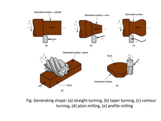
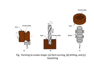
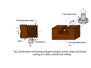
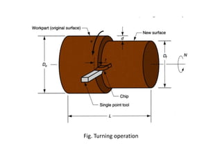
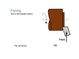
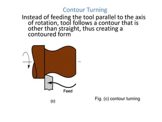
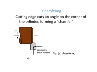
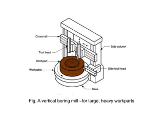
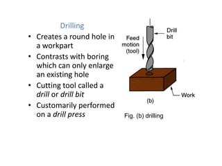
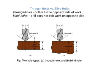
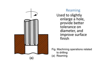
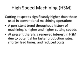
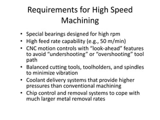
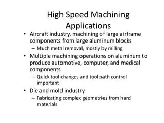
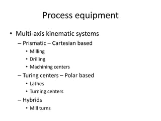

The document provides a comprehensive overview of various machining operations and machine tools, focusing on methods such as turning, drilling, milling, and high-speed machining. It details the characteristics and classifications of machined parts, the functioning of various machines like lathes and CNC machining centers, and the advantages of high-speed machining for production efficiency. Additionally, it covers specific techniques and tools used in these operations, along with their applications in different industries.


