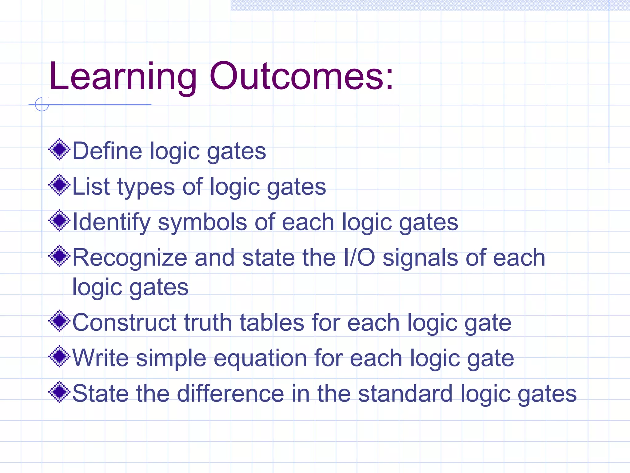
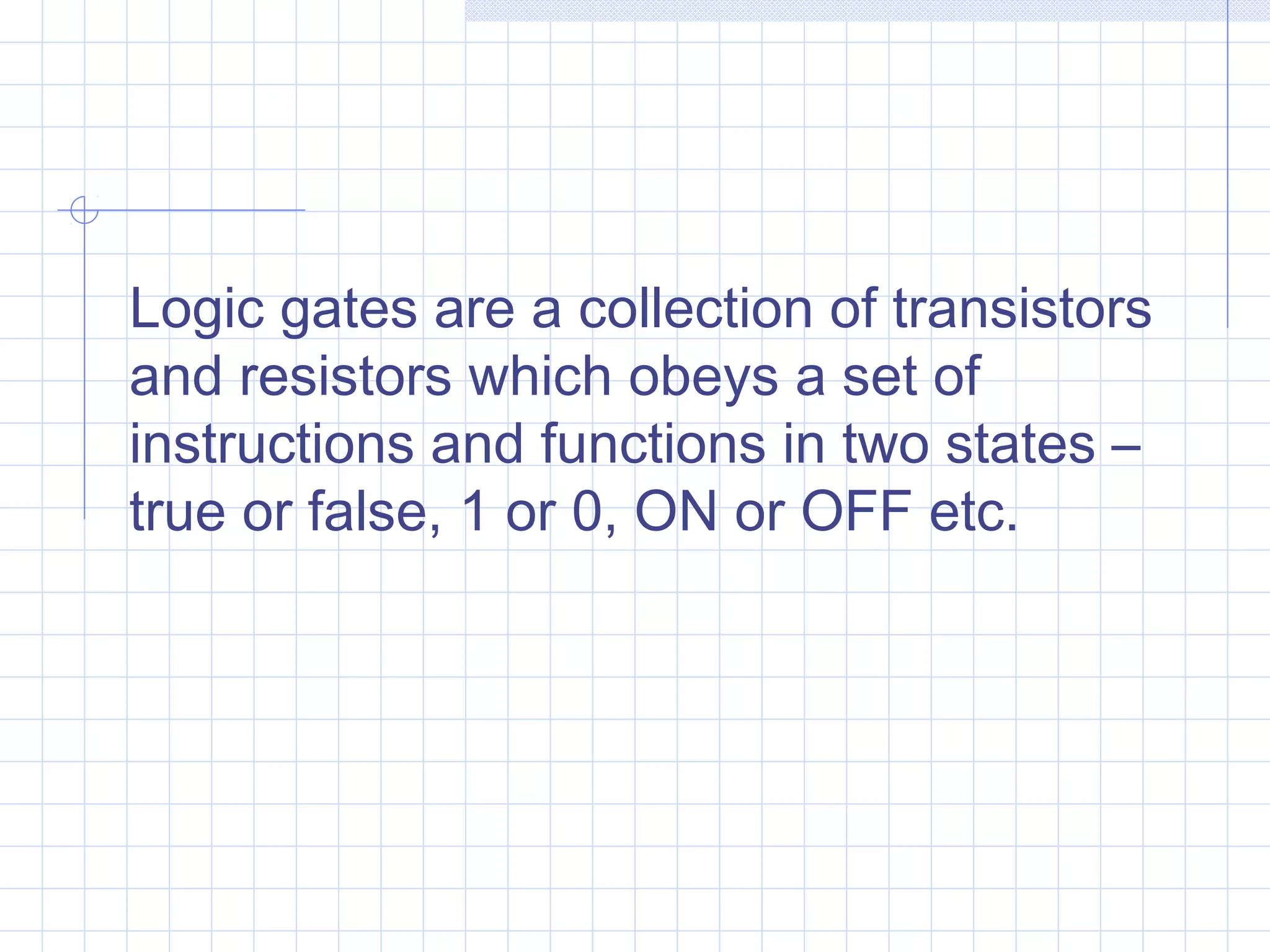
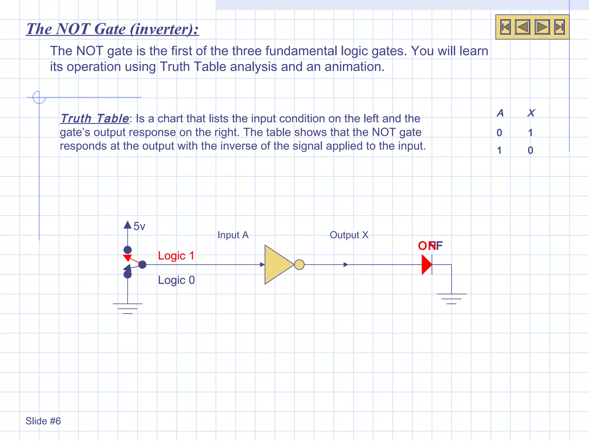
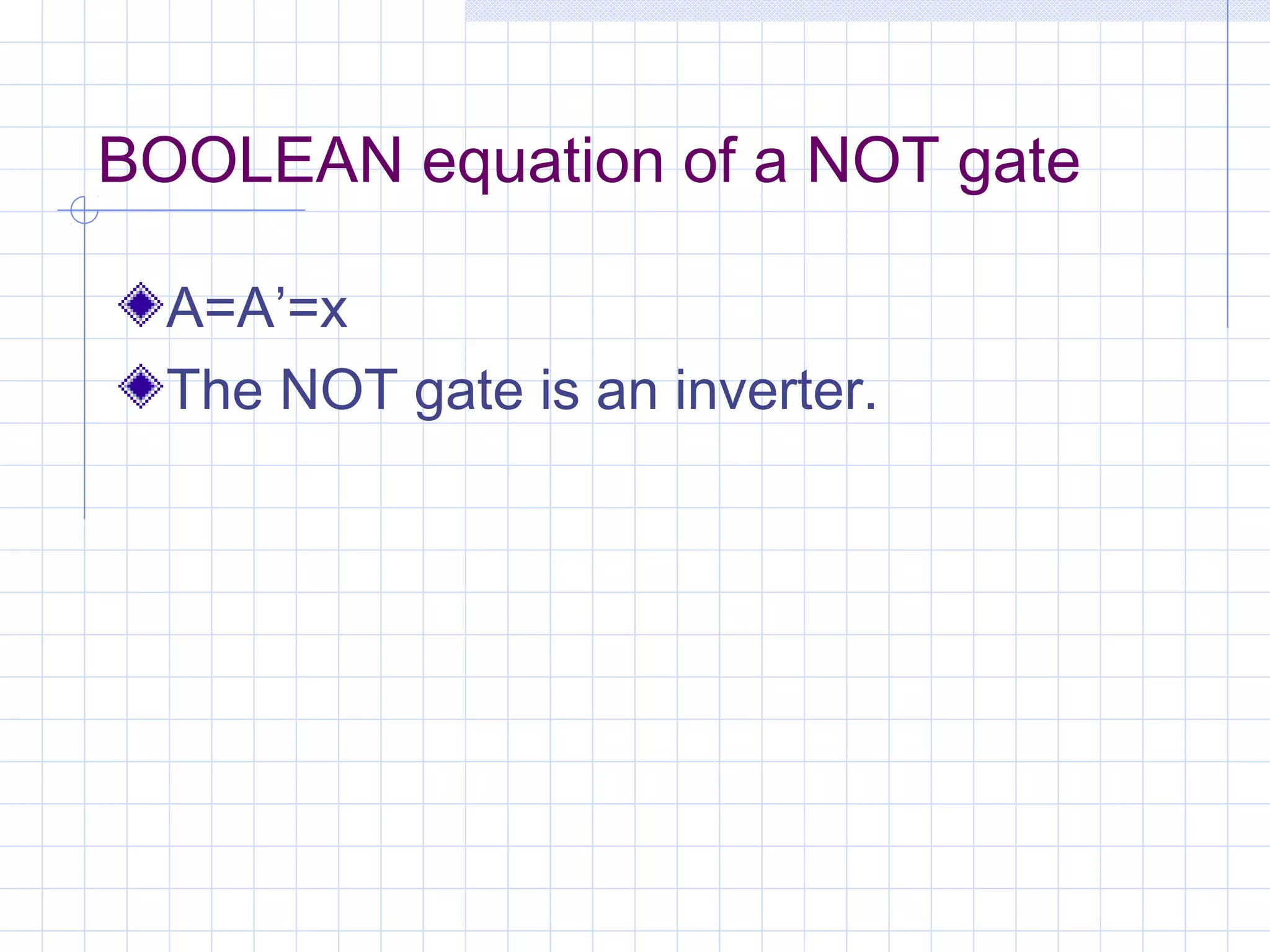
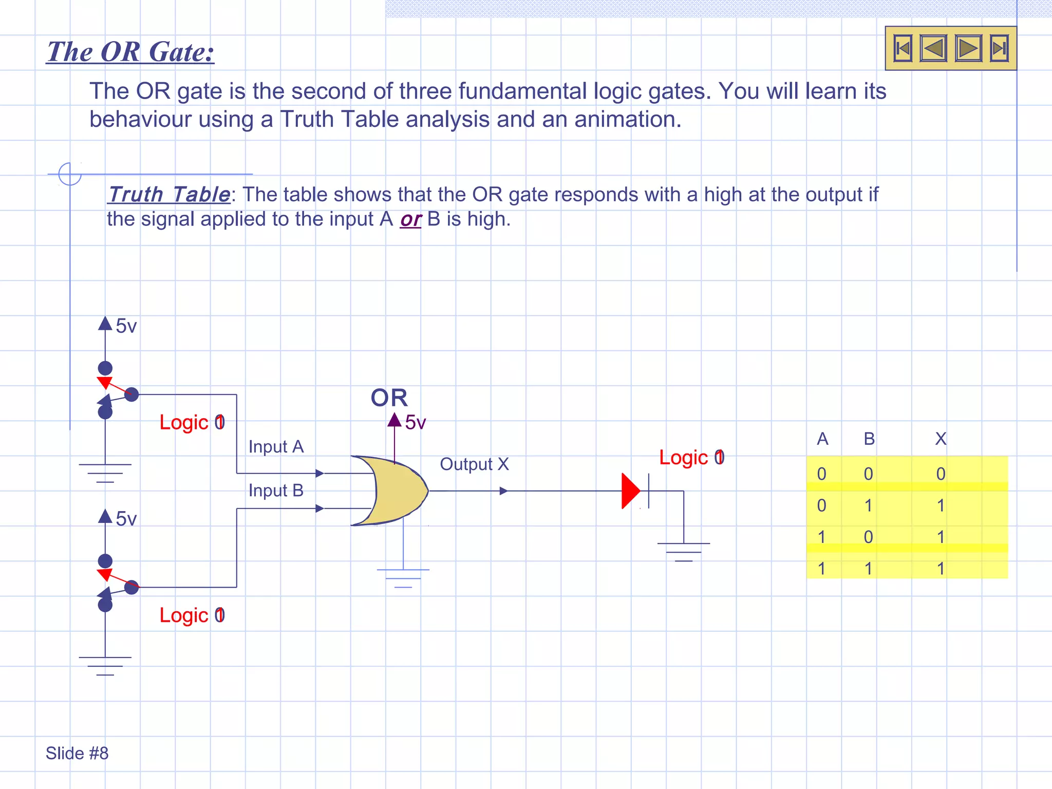
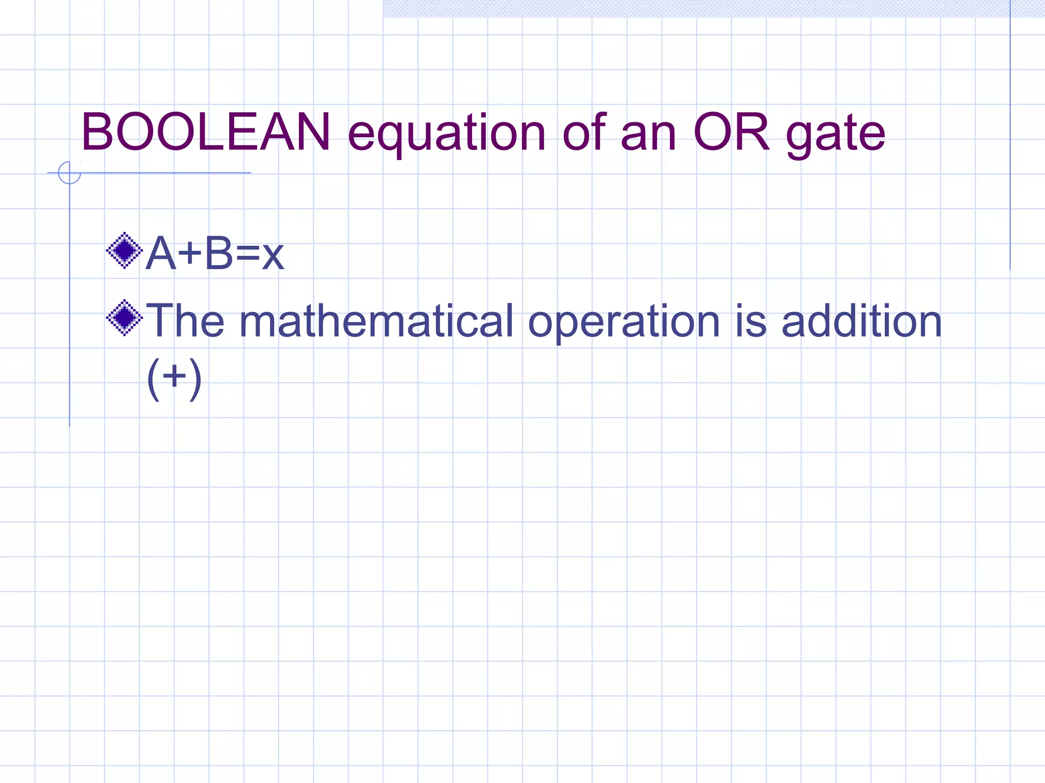
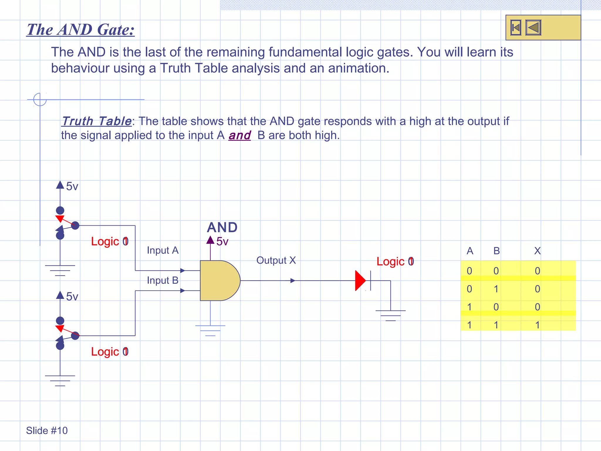
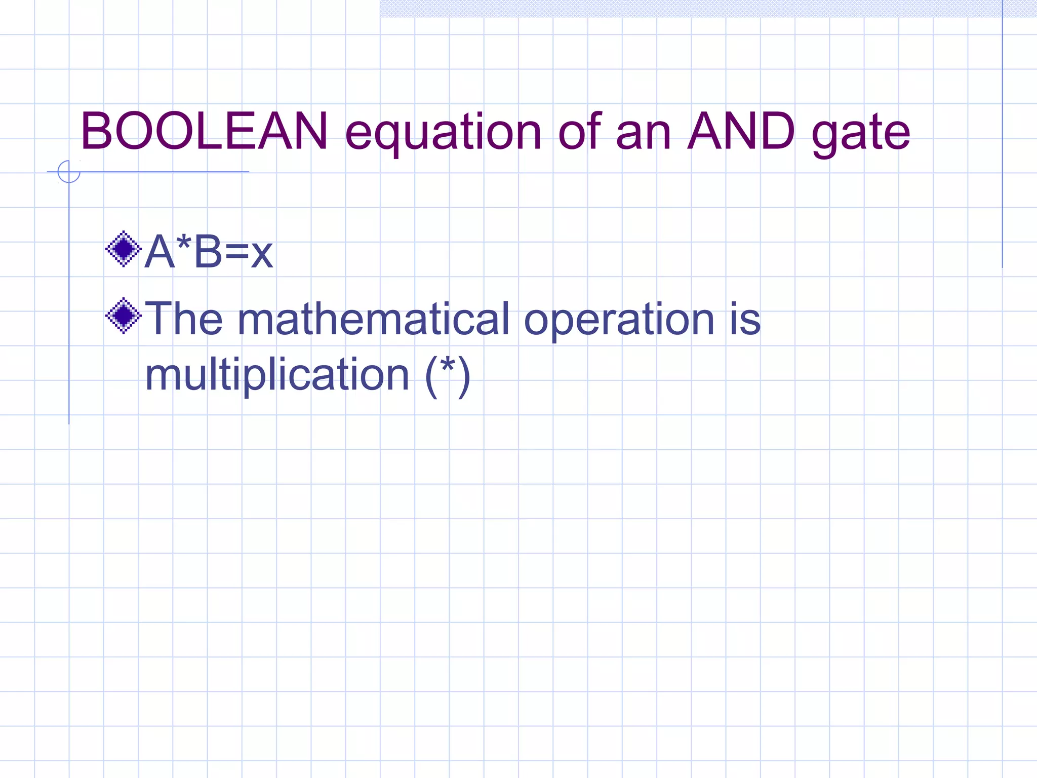
LOGIC GATES
Thursday, October 13, 2016
Learning Outcomes:
Define logic gates
List types of logic gates
Identify symbols of each logic gates
Recognize and state the I/O signals of each
logic gates
Construct truth tables for each logic gate
Write simple equation for each logic gate
State the difference in the standard logic gates
Logic gates are a collection of transistors
and resistors which obeys a set of
instructions and functions in two states –
true or false, 1 or 0, ON or OFF etc.
Types of logic gates
There are basically three(3) types of
logic gates:
1.AND
2.OR &
3.NOT gates
Logic Gates:
Slide #2
Slide #3
Slide #4
The NOT gate:
The OR gate:
The AND gate:
5v
The NOT gate is the first of the three fundamental logic gates. You will learn
its operation using Truth Table analysis and an animation.
The NOT Gate (inverter):
Input A Output X
A X
0 1
1 0
Truth Table: Is a chart that lists the input condition on the left and the
gate’s output response on the right. The table shows that the NOT gate
responds at the output with the inverse of the signal applied to the input.
Slide #6
Logic 1
OFF
Logic 0
ON
Logic 1
OFF
Logic 0
ON
Logic 1
OFF
Logic 0
ON
BOOLEAN equation of a NOT gate
A=A’=x
The NOT gate is an inverter.
The OR Gate:
The OR gate is the second of three fundamental logic gates. You will learn its
behaviour using a Truth Table analysis and an animation.
Truth Table: The table shows that the OR gate responds with a high at the output if
the signal applied to the input A or B is high.
Input A
Output X
Input B
OR
5v
5v
5v
Slide #8
Logic 0
Logic 0
Logic 0
Logic 0
Logic 1
Logic 1
Logic 1
Logic 1
Logic 0
Logic 1
Logic 1
Logic 1
A B X
0 0 0
0 1 1
1 0 1
1 1 1
BOOLEAN equation of an OR gate
A+B=x
The mathematical operation is addition
(+)
The AND Gate:
The AND is the last of the remaining fundamental logic gates. You will learn its
behaviour using a Truth Table analysis and an animation.
Truth Table: The table shows that the AND gate responds with a high at the output if
the signal applied to the input A and B are both high.
5v
5v
5v
Input A
Output X
Input B
AND
Slide #10
Logic 0
Logic 0
Logic 0
Logic 0
Logic 0
Logic 1
Logic 1
Logic 0
Logic 0
Logic 1
Logic 1
Logic 1
A B X
0 0 0
0 1 0
1 0 0
1 1 1
BOOLEAN equation of an AND gate
A*B=x
The mathematical operation is
multiplication (*)
Assignment
State the uses of logic gates
Define alternative logic gates
State types of alternative logic gate
Draw their logic symbols, truth tables
and logic equations
State uses of alternative logic gates
Word list
Logic
I/O – Input/Output
Truth table
Boolean algebra
Alternative

Logic gates i & ii

  • 1.
  • 2.
    Learning Outcomes: Define logicgates List types of logic gates Identify symbols of each logic gates Recognize and state the I/O signals of each logic gates Construct truth tables for each logic gate Write simple equation for each logic gate State the difference in the standard logic gates
  • 3.
    Logic gates area collection of transistors and resistors which obeys a set of instructions and functions in two states – true or false, 1 or 0, ON or OFF etc.
  • 4.
    Types of logicgates There are basically three(3) types of logic gates: 1.AND 2.OR & 3.NOT gates
  • 5.
    Logic Gates: Slide #2 Slide#3 Slide #4 The NOT gate: The OR gate: The AND gate:
  • 6.
    5v The NOT gateis the first of the three fundamental logic gates. You will learn its operation using Truth Table analysis and an animation. The NOT Gate (inverter): Input A Output X A X 0 1 1 0 Truth Table: Is a chart that lists the input condition on the left and the gate’s output response on the right. The table shows that the NOT gate responds at the output with the inverse of the signal applied to the input. Slide #6 Logic 1 OFF Logic 0 ON Logic 1 OFF Logic 0 ON Logic 1 OFF Logic 0 ON
  • 7.
    BOOLEAN equation ofa NOT gate A=A’=x The NOT gate is an inverter.
  • 8.
    The OR Gate: TheOR gate is the second of three fundamental logic gates. You will learn its behaviour using a Truth Table analysis and an animation. Truth Table: The table shows that the OR gate responds with a high at the output if the signal applied to the input A or B is high. Input A Output X Input B OR 5v 5v 5v Slide #8 Logic 0 Logic 0 Logic 0 Logic 0 Logic 1 Logic 1 Logic 1 Logic 1 Logic 0 Logic 1 Logic 1 Logic 1 A B X 0 0 0 0 1 1 1 0 1 1 1 1
  • 9.
    BOOLEAN equation ofan OR gate A+B=x The mathematical operation is addition (+)
  • 10.
    The AND Gate: TheAND is the last of the remaining fundamental logic gates. You will learn its behaviour using a Truth Table analysis and an animation. Truth Table: The table shows that the AND gate responds with a high at the output if the signal applied to the input A and B are both high. 5v 5v 5v Input A Output X Input B AND Slide #10 Logic 0 Logic 0 Logic 0 Logic 0 Logic 0 Logic 1 Logic 1 Logic 0 Logic 0 Logic 1 Logic 1 Logic 1 A B X 0 0 0 0 1 0 1 0 0 1 1 1
  • 11.
    BOOLEAN equation ofan AND gate A*B=x The mathematical operation is multiplication (*)
  • 12.
    Assignment State the usesof logic gates Define alternative logic gates State types of alternative logic gate Draw their logic symbols, truth tables and logic equations State uses of alternative logic gates
  • 13.
    Word list Logic I/O –Input/Output Truth table Boolean algebra Alternative