Downloaded 163 times

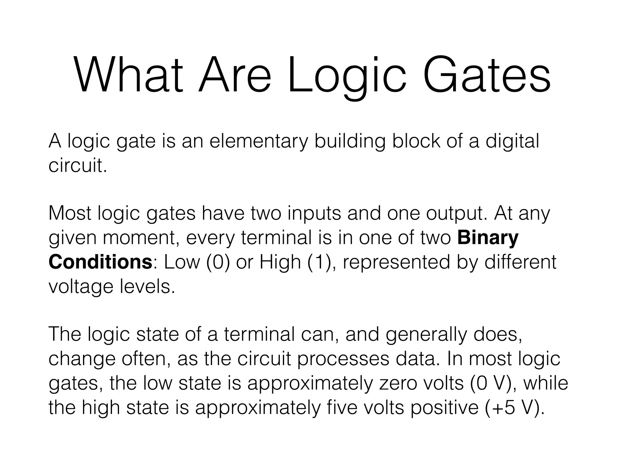
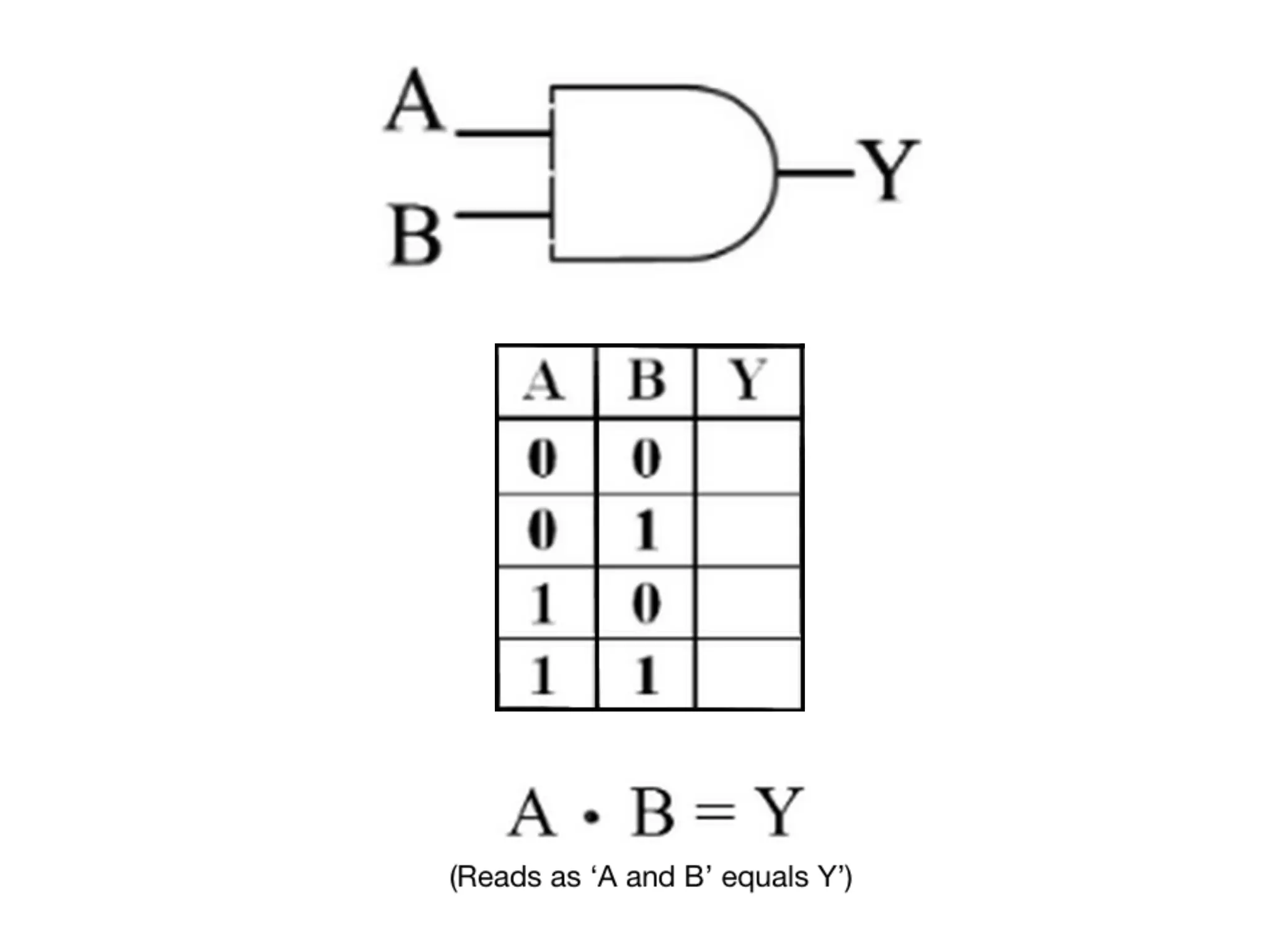
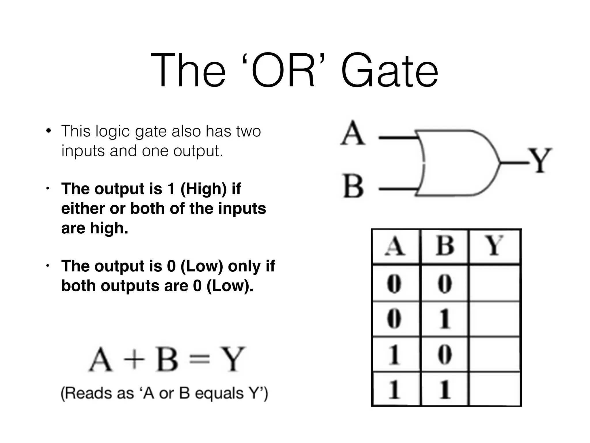
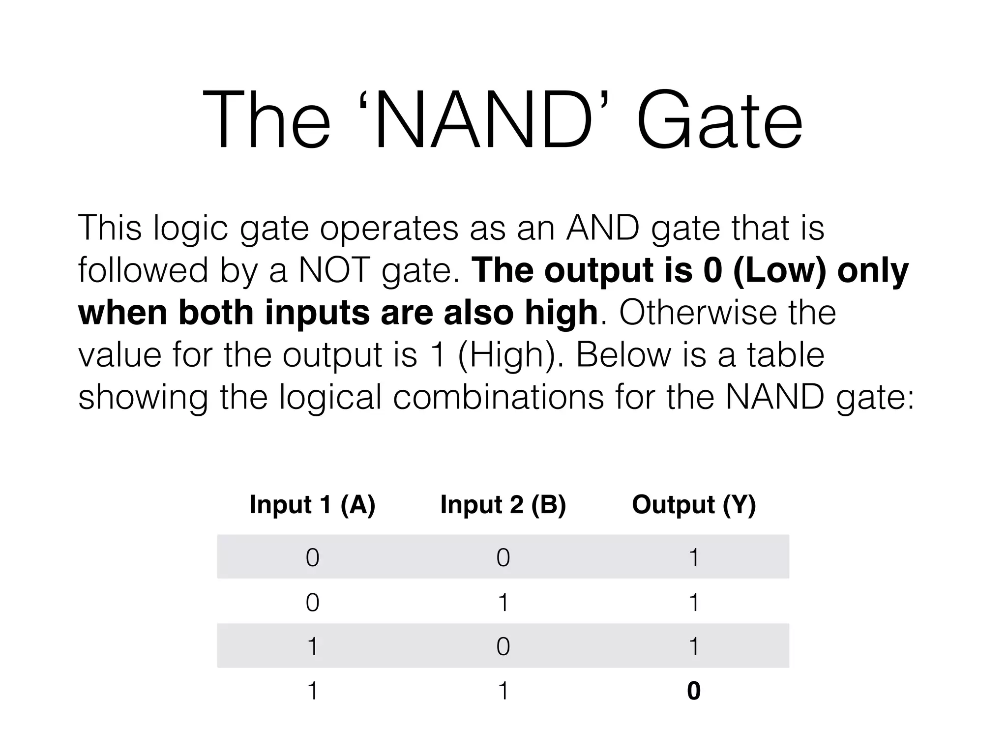
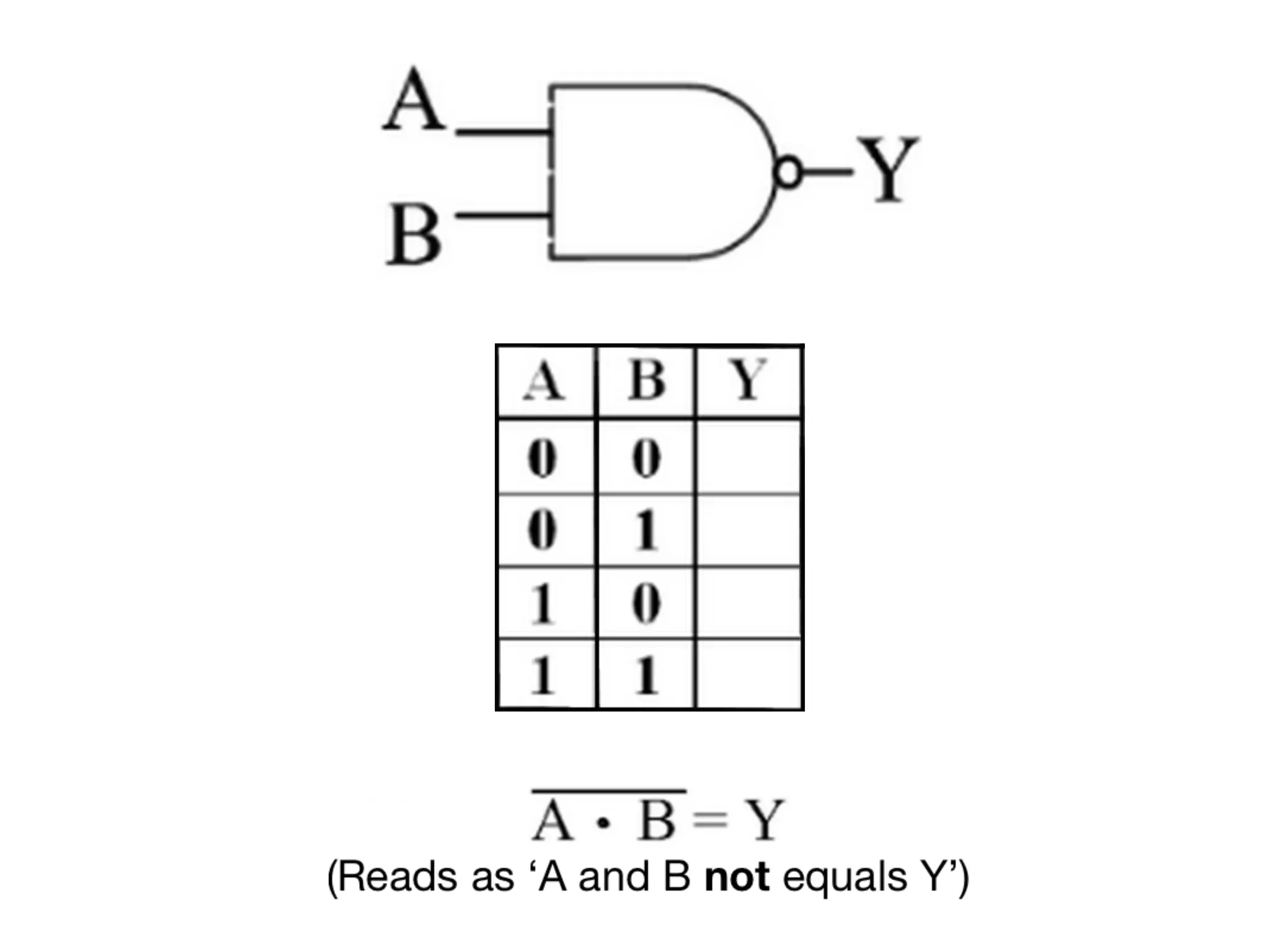
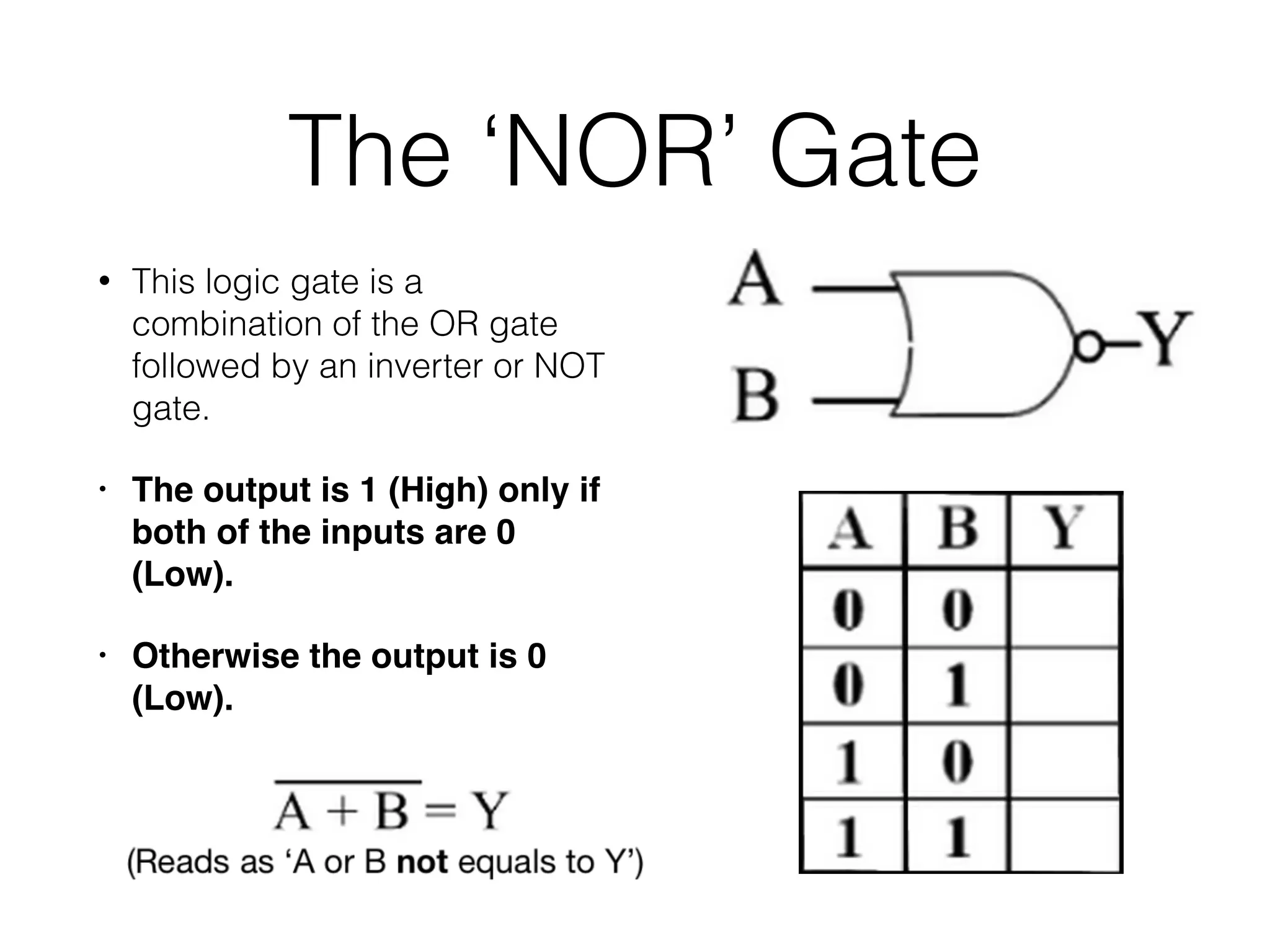
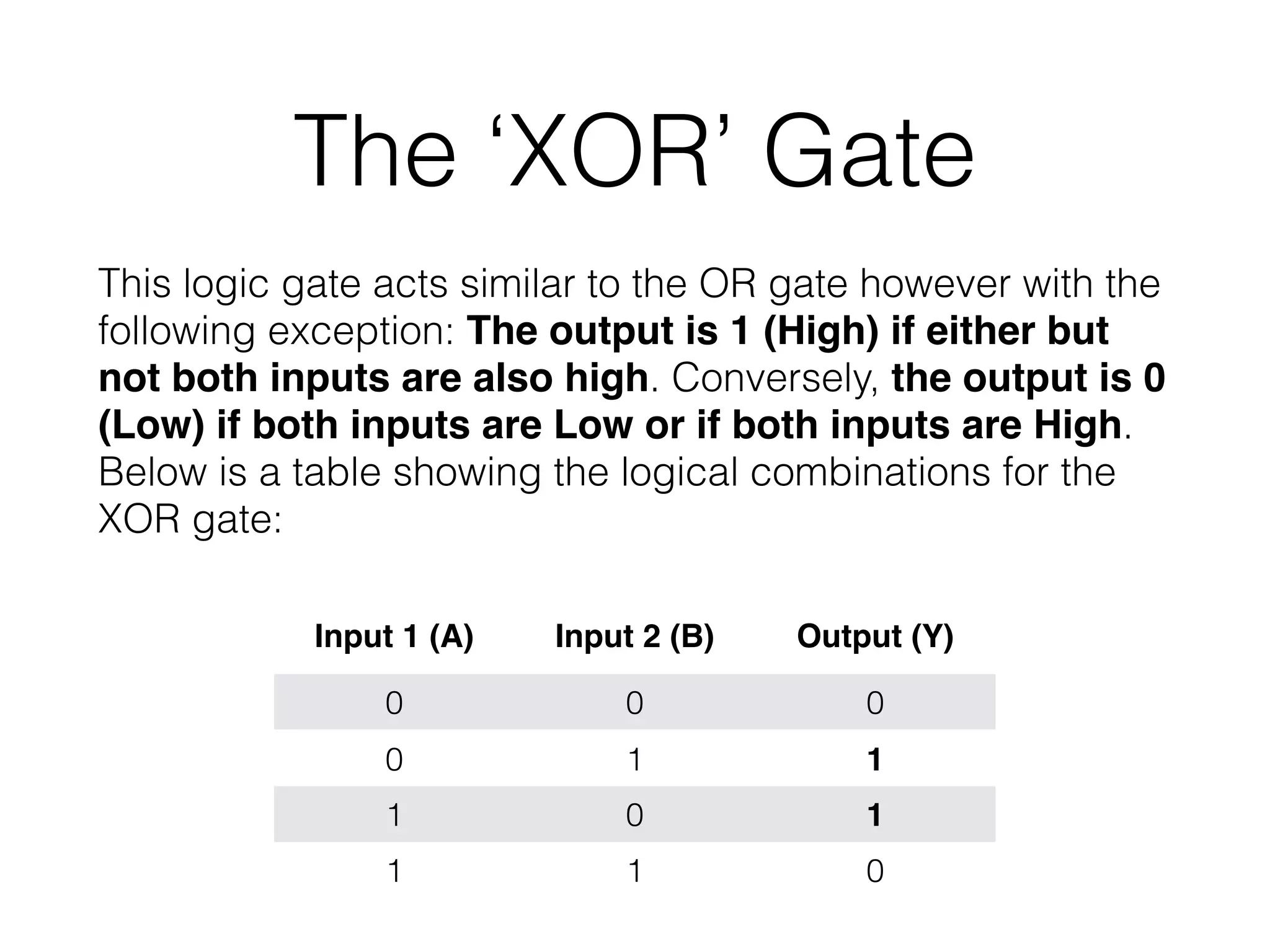
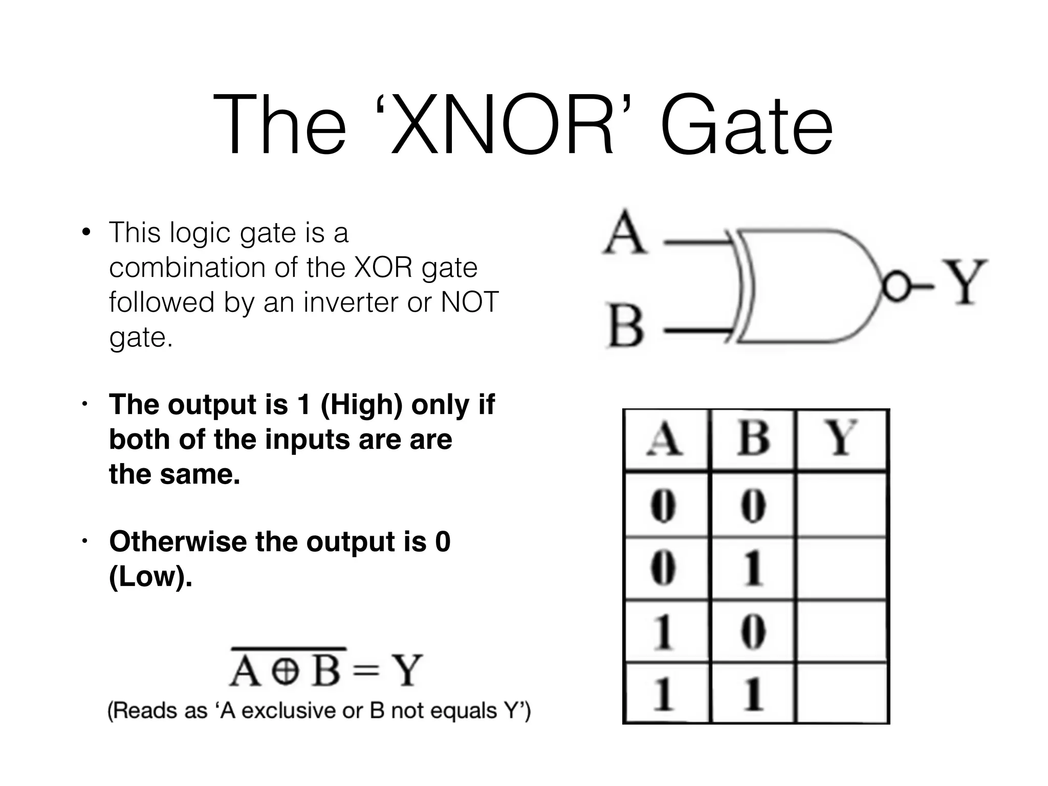
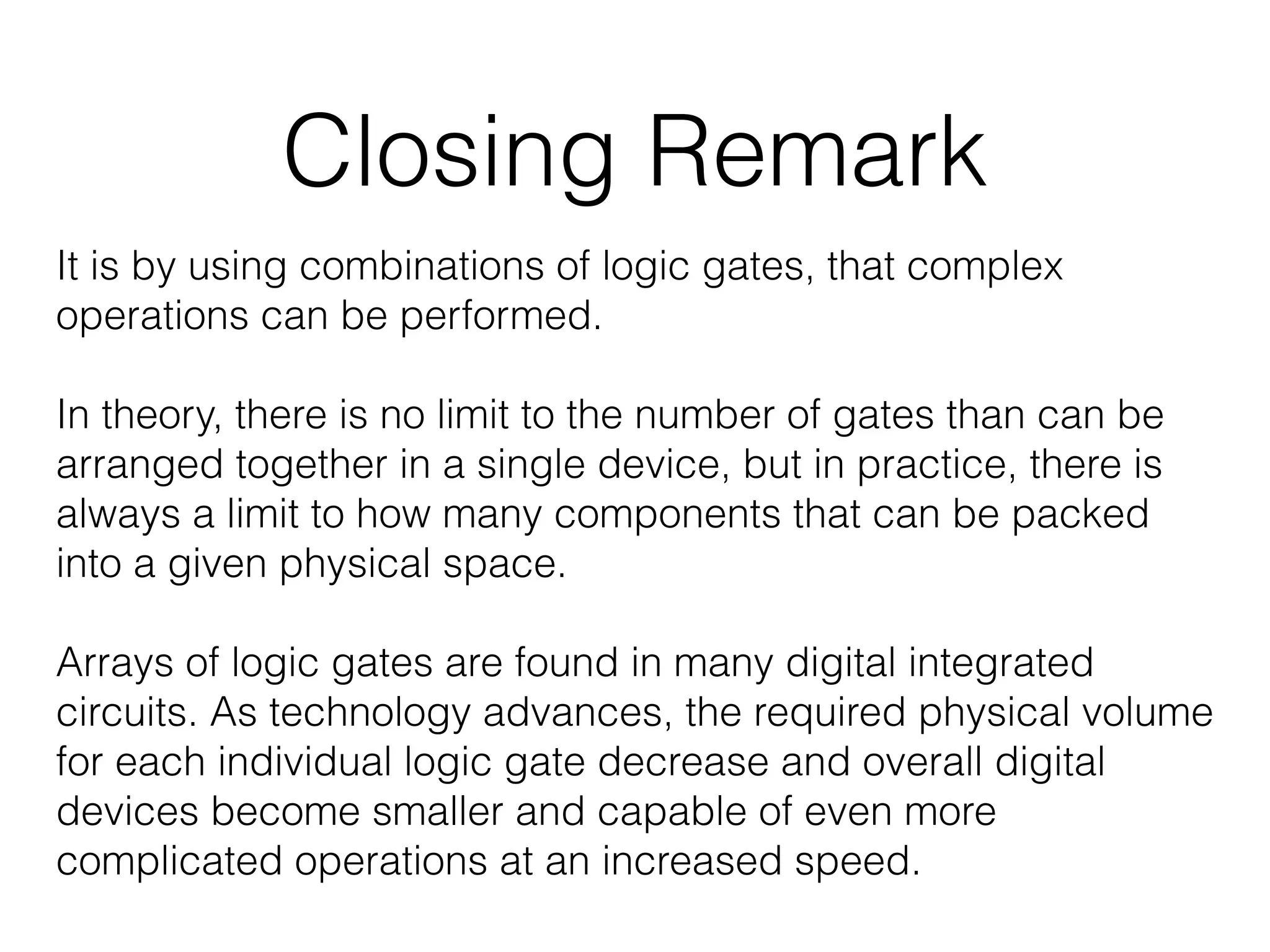

This document introduces logic gates, which are fundamental components of digital circuits, typically featuring two inputs and one output that can represent binary states (0 or 1). It describes seven basic types of logic gates: NOT, AND, OR, NAND, NOR, XOR, and XNOR, detailing their functions and truth tables. The text concludes by emphasizing that combinations of these gates can perform complex operations, and advances in technology allow for more compact and efficient integrated circuits.


![De Morgan Theorem B[1]](https://cdn.slidesharecdn.com/ss_thumbnails/demorgantheoremb1-090930110355-phpapp01-thumbnail.jpg?width=640&height=640&fit=bounds)


![067 [BEEE].pptx](https://cdn.slidesharecdn.com/ss_thumbnails/067beee-230703042004-87a7ab4e-thumbnail.jpg?width=640&height=640&fit=bounds)
![067 [BEEE].pptx](https://cdn.slidesharecdn.com/ss_thumbnails/067beee-230703041908-0bac0dfc-thumbnail.jpg?width=640&height=640&fit=bounds)


