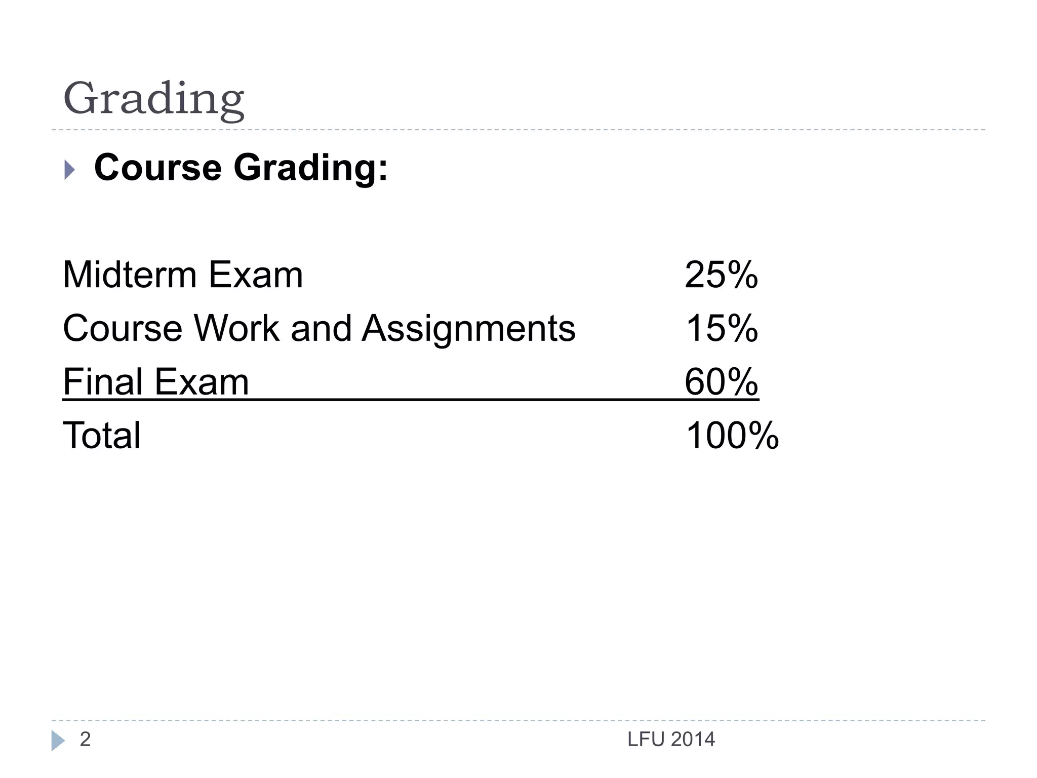
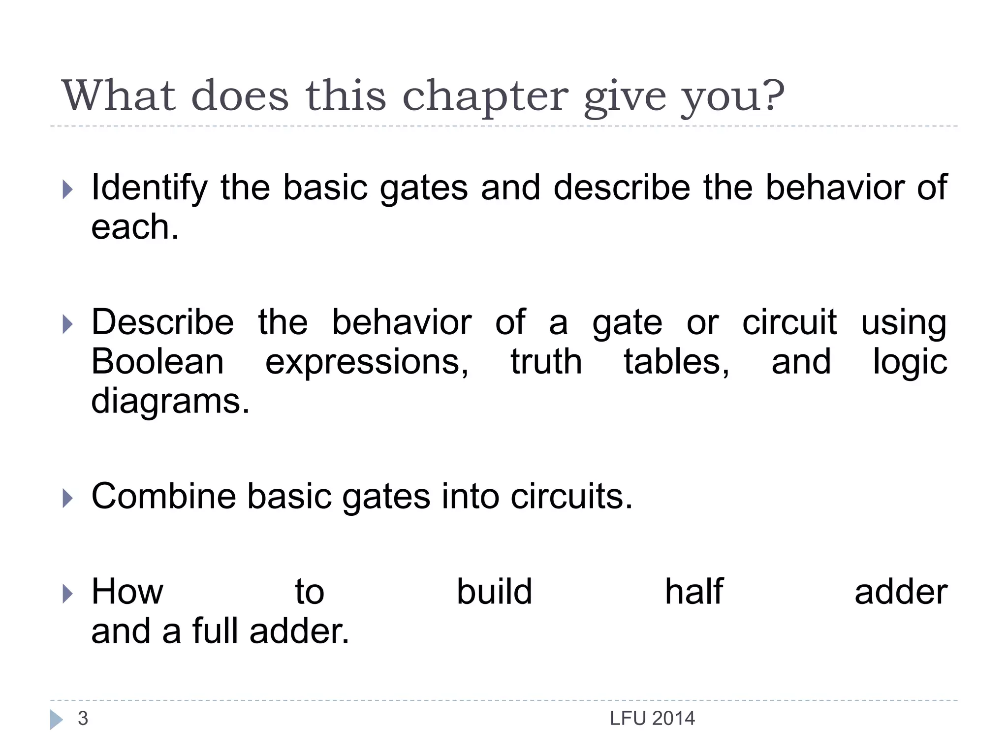
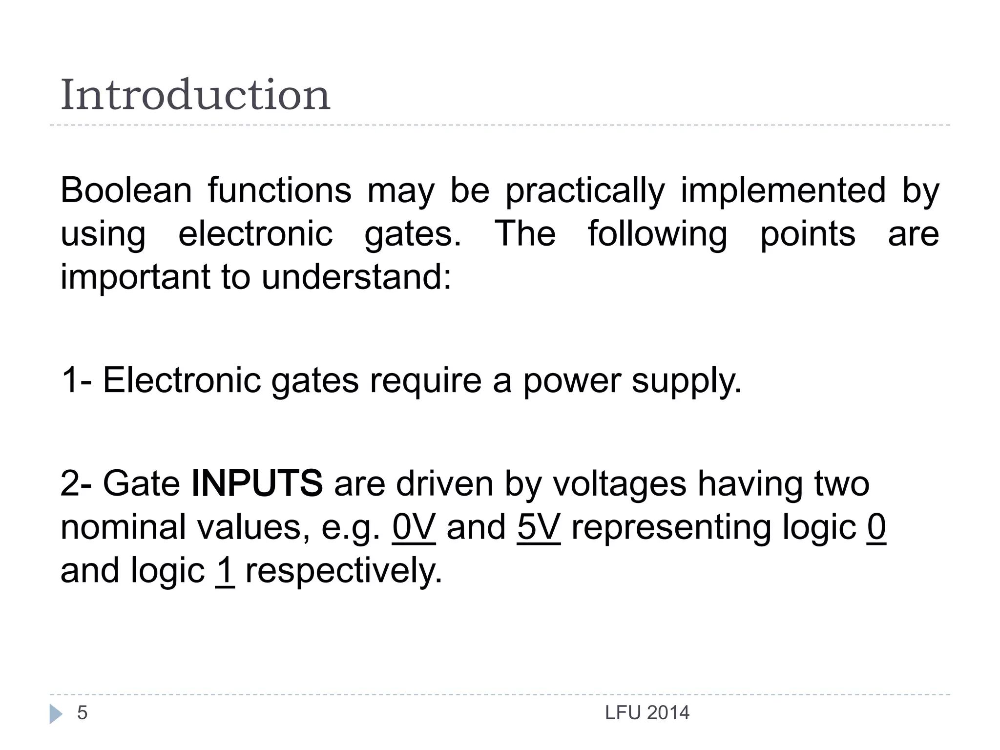
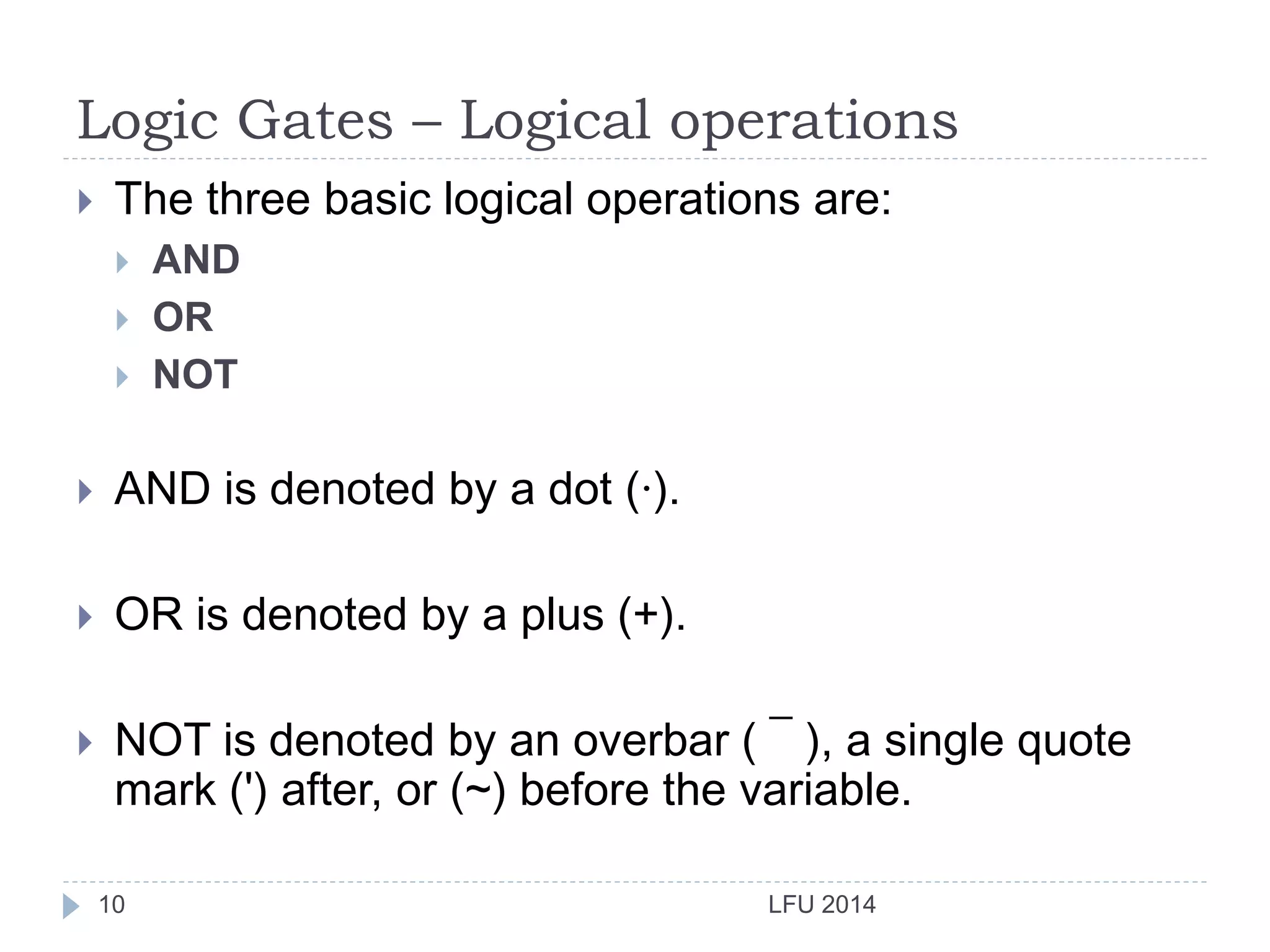
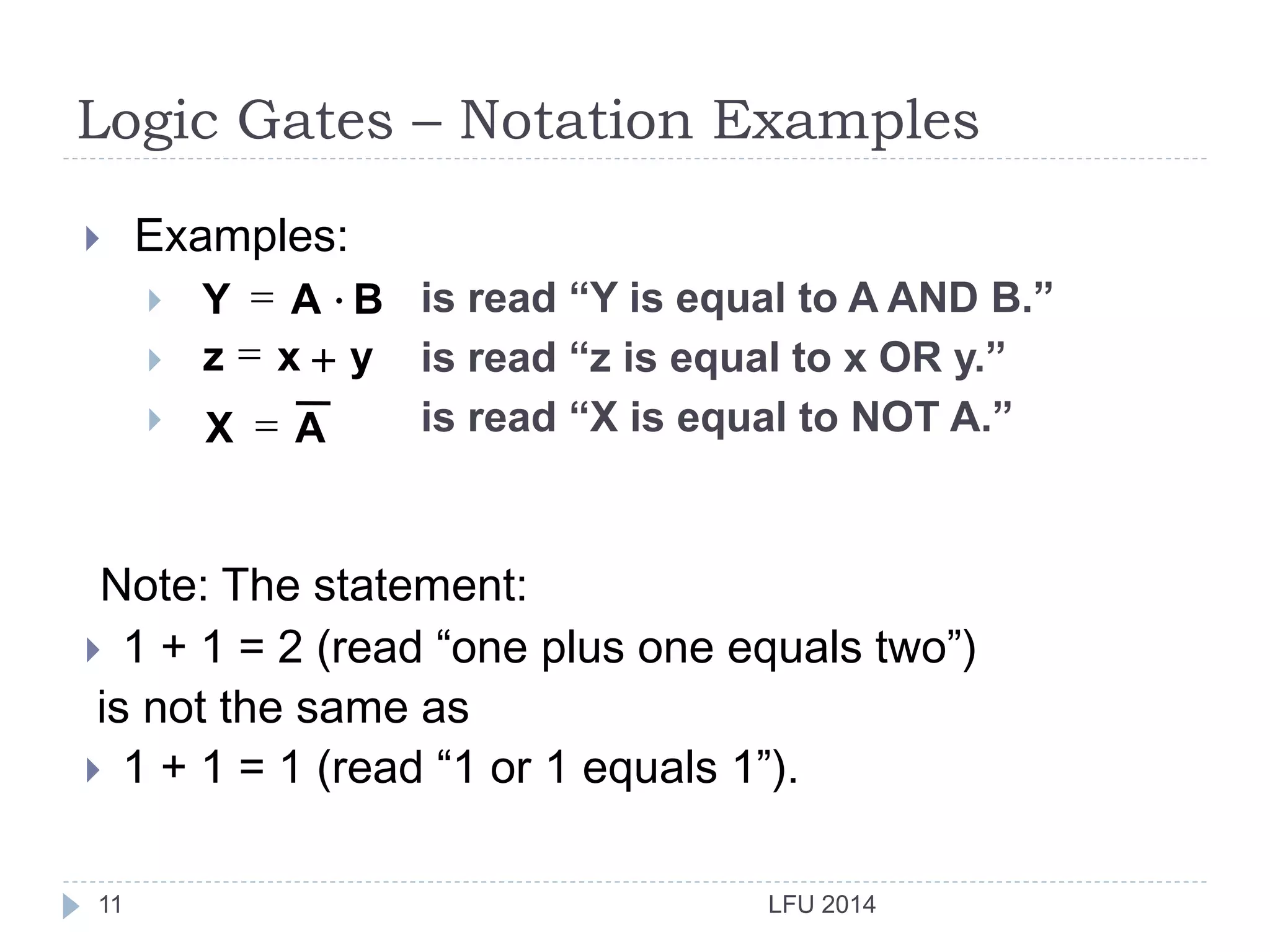
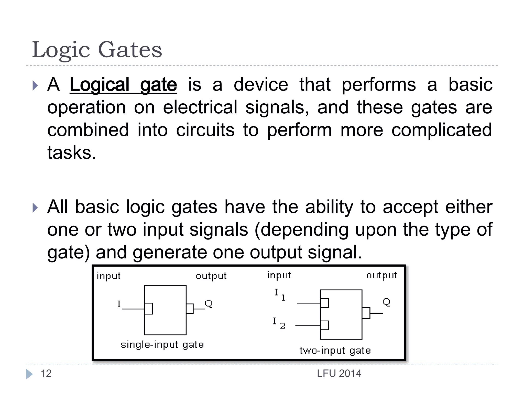
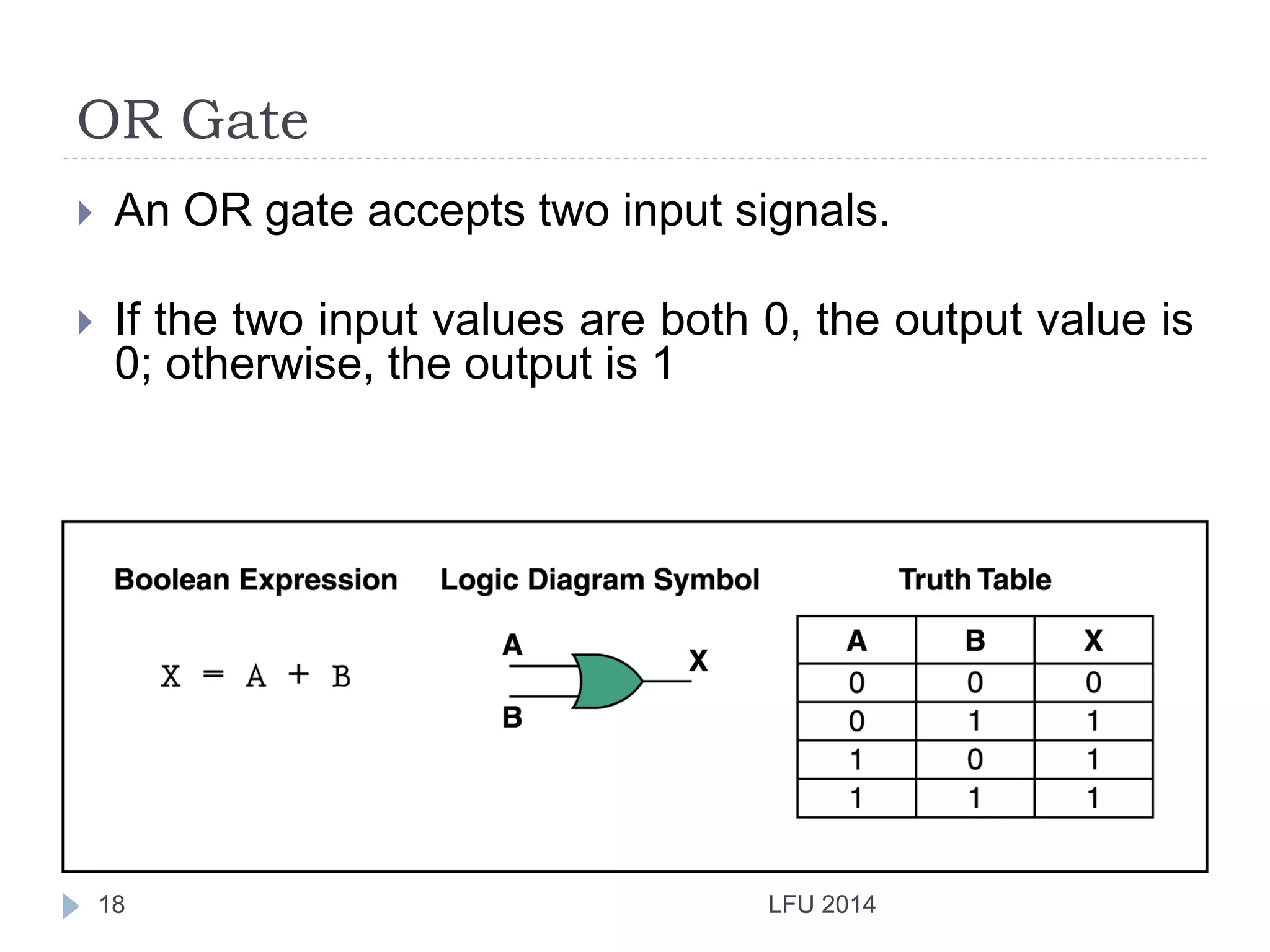
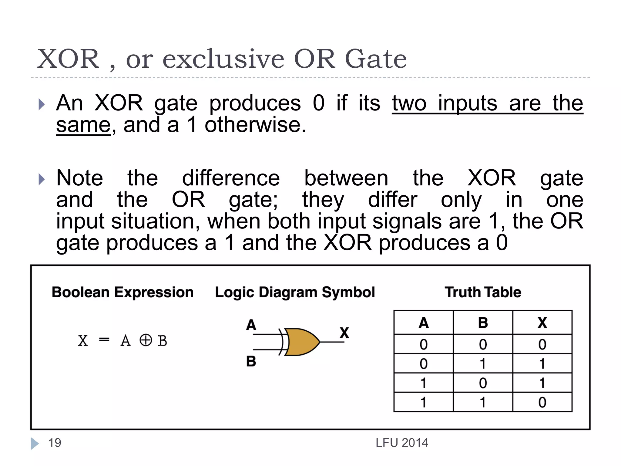
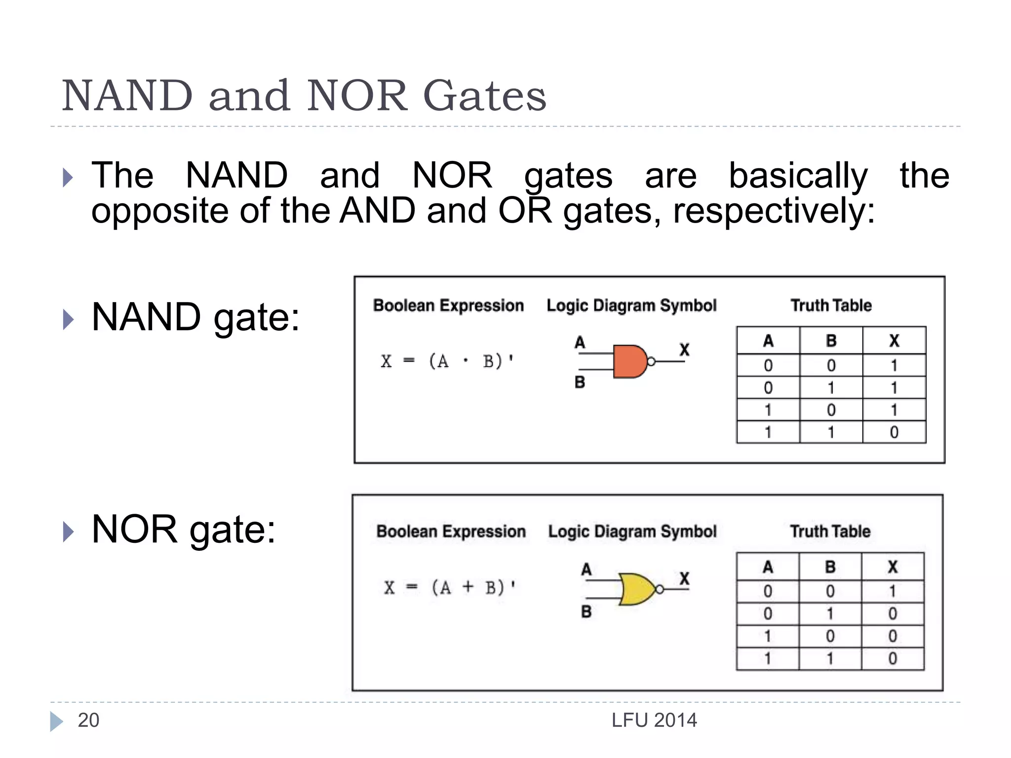
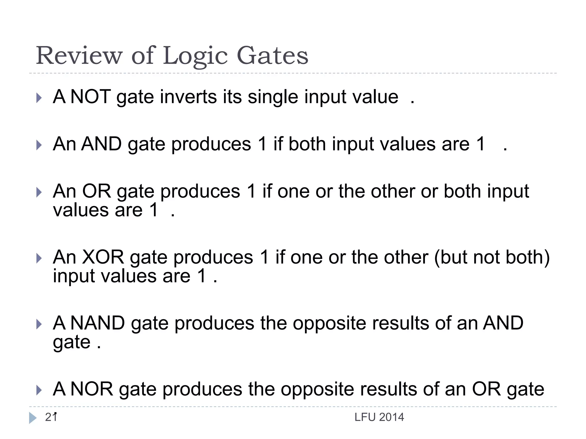
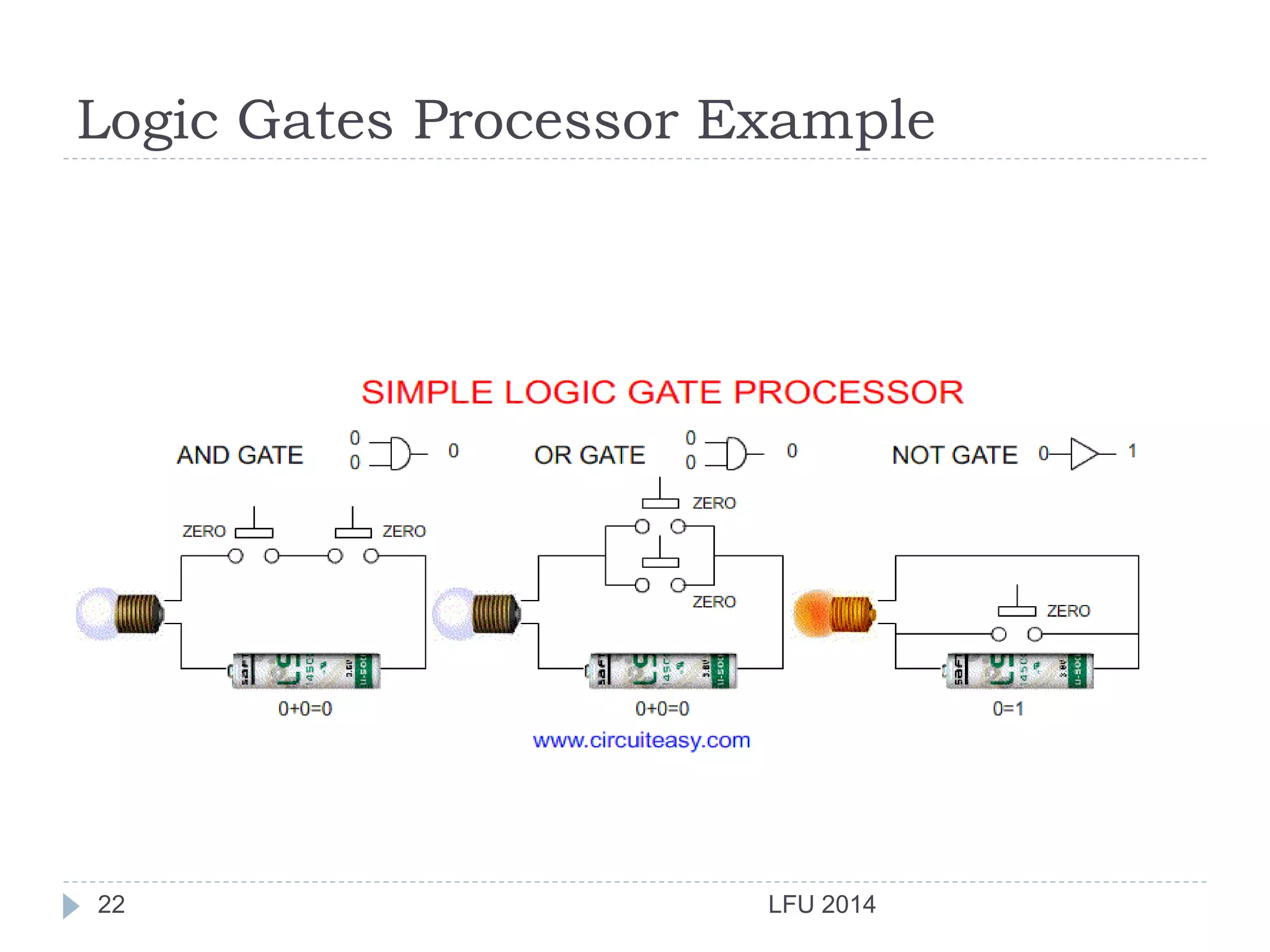
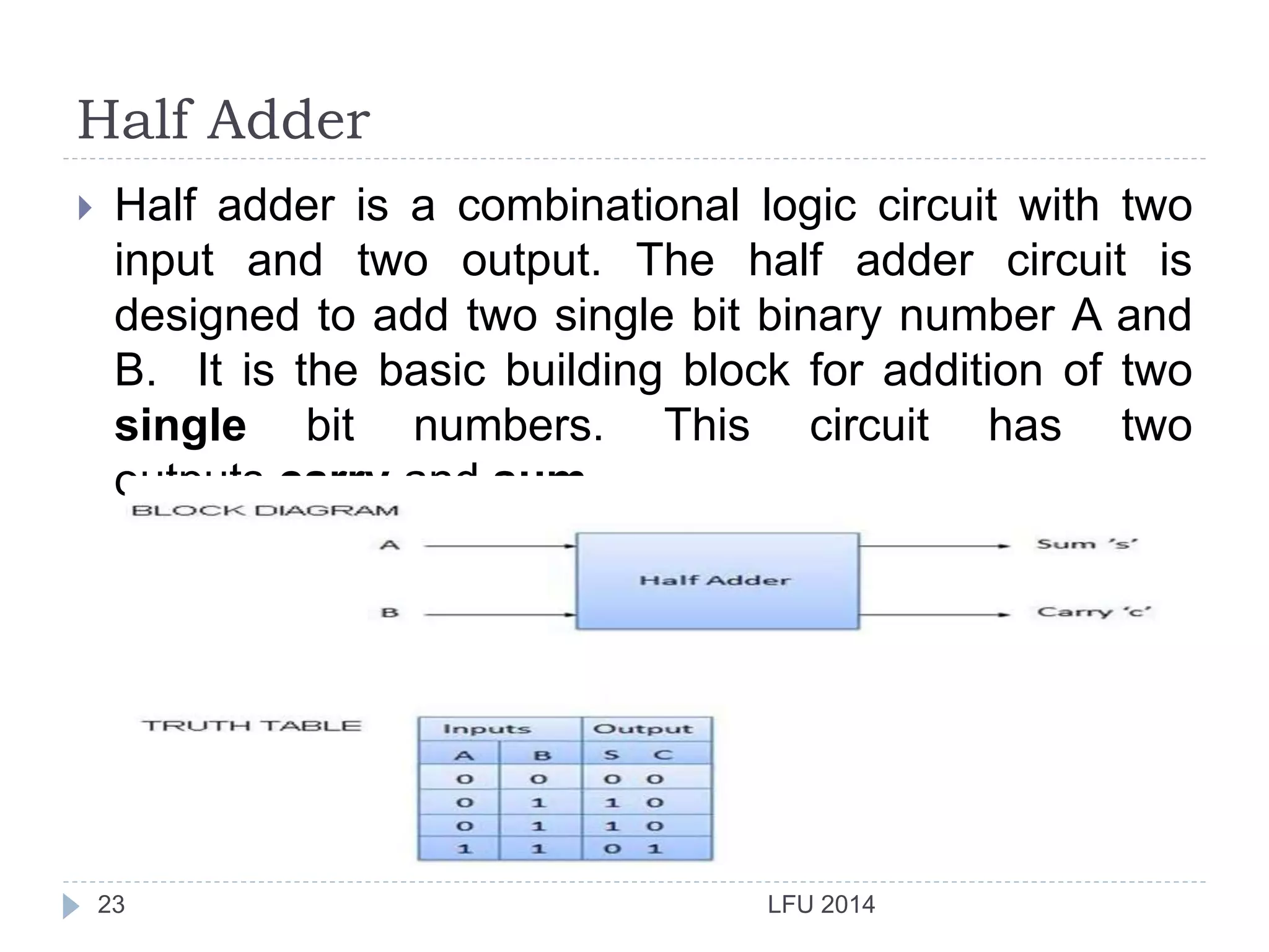
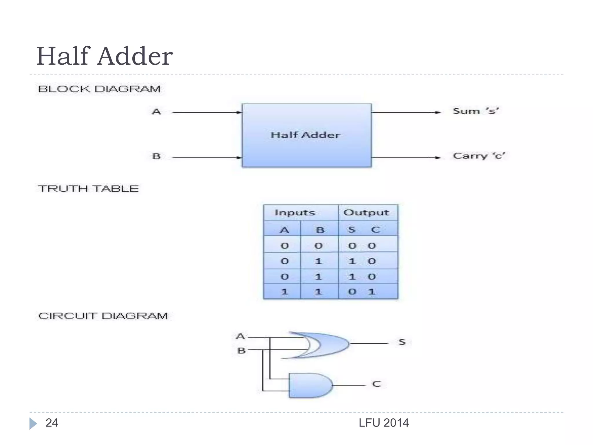
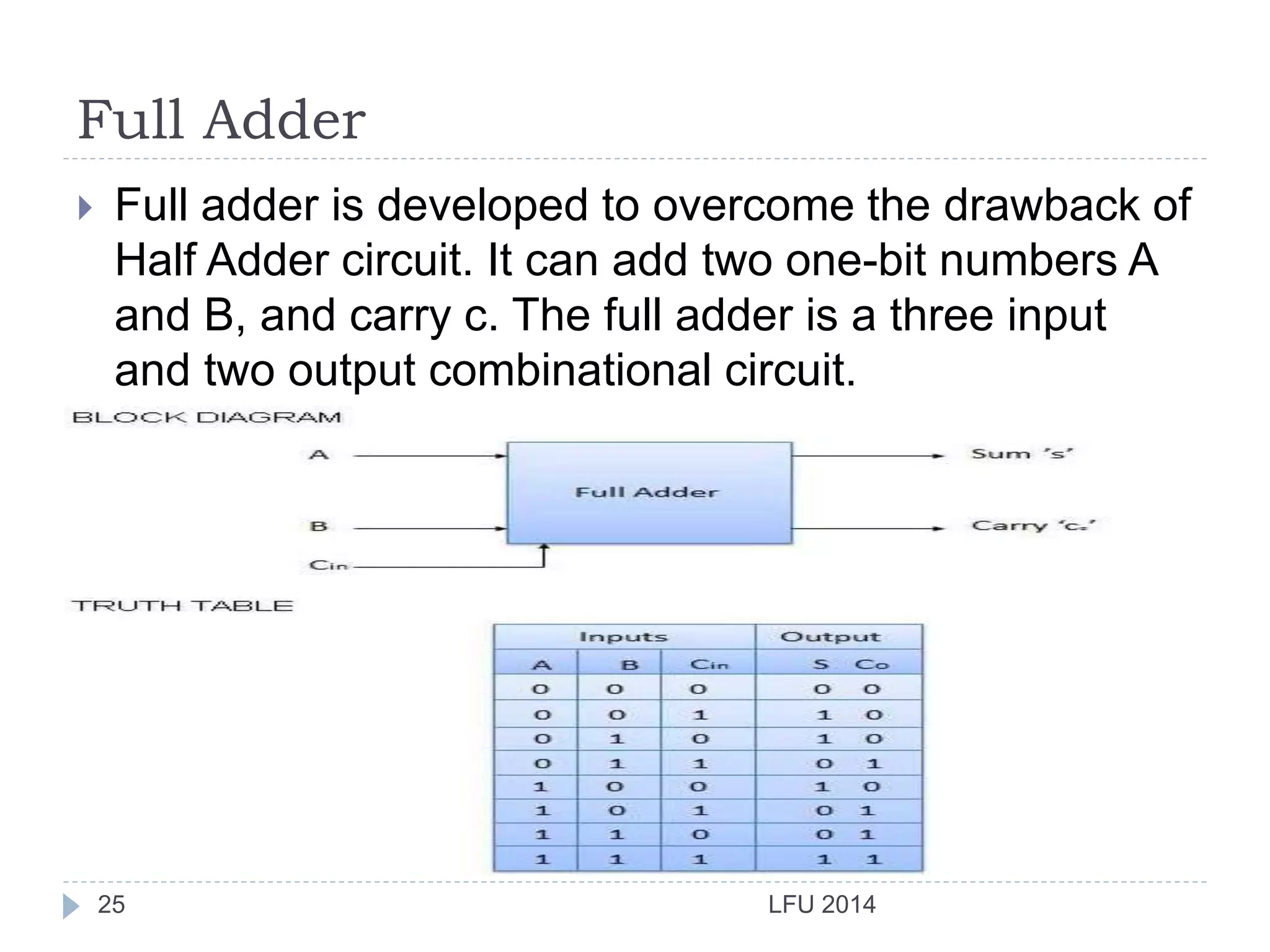
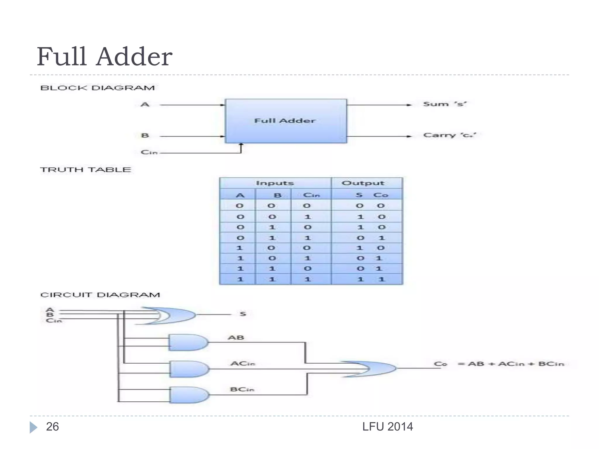
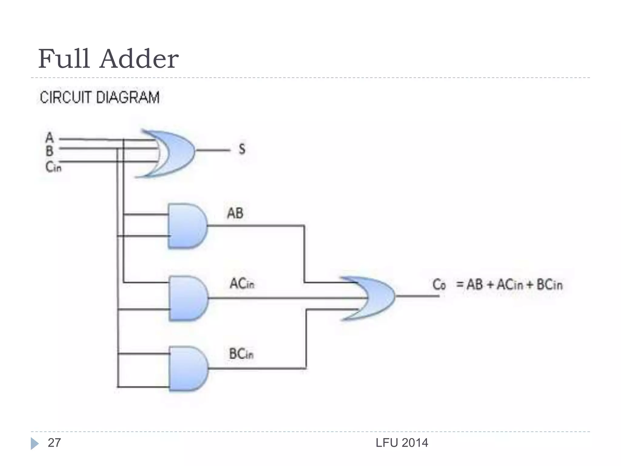
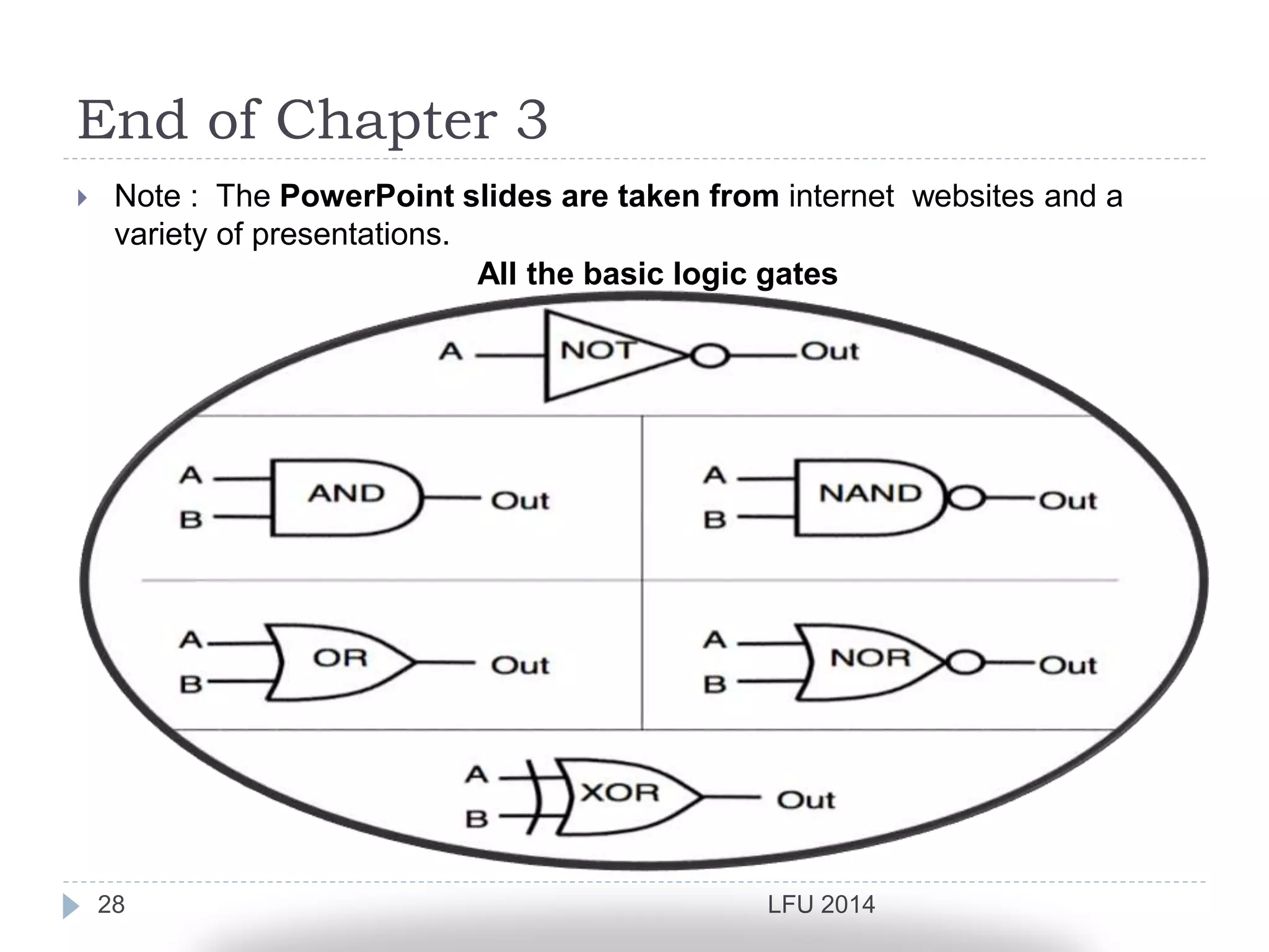
Digital Logic Design
IT101LGD
Prepared By
Asst. Lect. Mohammed Salim
Department of IT
1 LFU 2014
Grading
LFU 20142
 Course Grading:
Midterm Exam 25%
Course Work and Assignments 15%
Final Exam 60%
Total 100%
What does this chapter give you?
LFU 20143
 Identify the basic gates and describe the behavior of
each.
 Describe the behavior of a gate or circuit using
Boolean expressions, truth tables, and logic
diagrams.
 Combine basic gates into circuits.
 How to build half adder
and a full adder.
Contents
LFU 20144
Introduction
Logic Gates
Half-Adder
Full-Adder
Introduction
LFU 20145
Boolean functions may be practically implemented by
using electronic gates. The following points are
important to understand:
1- Electronic gates require a power supply.
2- Gate INPUTS are driven by voltages having two
nominal values, e.g. 0V and 5V representing logic 0
and logic 1 respectively.
Introduction
LFU 20146
3- The OUTPUT of a gate provides two nominal values
of voltage only, e.g. 0V and 5V representing logic 0
and logic 1 respectively. In general, there is only one
output to a logic gate except in some special cases.
4- There is always a time delay between an input
being applied and the output responding.
Introduction
Transistor Building Block of Computers
 Microprocessors contain millions of transistors
 Intel Pentium 4 (2000): 48 million
 IBM PowerPC 750FX (2002): 38 million
 IBM/Apple PowerPC G5 (2003): 58 million
 Logically, each transistor acts as a switch
Combined to implement logic functions
 AND, OR, NOT
 Combined to build higher-level structures
 Adder, multiplexer, decoder, register, …
Logic Gates – Binary Logic
LFU 20148
 Binary variables take one of two values.
 Logical operators operate on binary values and
binary variables.
 Basic logical operators are the logic functions AND,
OR and NOT.
 Logic gates implement logic functions.
 Boolean Algebra: a useful mathematical system for
specifying and transforming logic functions.
 We study Boolean algebra as a foundation for
designing and analyzing digital systems!
Logic Gates – Binary Variables
LFU 20149
 Remember that the two binary values have different
names:
 True/False
 On/Off
 Yes/No
 1/0
 We use 1 and 0 to denote the two values.
 Variable identifier examples:
 A, B, y, z
Logic Gates – Logical operations
LFU 201410
 The three basic logical operations are:
 AND
 OR
 NOT
 AND is denoted by a dot (·).
 OR is denoted by a plus (+).
 NOT is denoted by an overbar ( ¯ ), a single quote
mark (') after, or (~) before the variable.
Logic Gates – Notation Examples
LFU 201411
 Examples:
 is read “Y is equal to A AND B.”
 is read “z is equal to x OR y.”
 is read “X is equal to NOT A.”
Note: The statement:
 1 + 1 = 2 (read “one plus one equals two”)
is not the same as
 1 + 1 = 1 (read “1 or 1 equals 1”).
= BAY 
yxz +=
AX =
Logic Gates
LFU 201412
 A Logical gate is a device that performs a basic
operation on electrical signals, and these gates are
combined into circuits to perform more complicated
tasks.
 All basic logic gates have the ability to accept either
one or two input signals (depending upon the type of
gate) and generate one output signal.
Logic Gates Representation
LFU 201413
 There are three different methods for describing the
behavior of gates and circuits:
 Boolean expressions
 Logic diagrams
 Truth tables
Logic Gates Representation
LFU 201414
 Boolean expressions: expressions in this algebraic
notation are an smart way to show the activity of
electrical circuits.
 Logic diagrams: a graphical representation of a
circuit and each type of gate is represented by a
specific graphical symbol
 Truth tables: defines the function of a gate by listing
all possible input combinations that the gate could
encounter, and the corresponding output
Logic Gates
LFU 201415
 Let’s take the processing of the following six types of
gates:
 NOT
 AND
 OR
 NAND
 NOR
 XOR
NOT Gate
LFU 201416
 A NOT gate accepts only one input value
and produces one output value
 By definition, if the input value for a NOT gate is 0,
the output value is 1, and if the input value is 1, the
output is 0
 A NOT gate is sometimes called as an inverter
because it inverts the input value
AND Gate
LFU 201417
 An AND gate accepts two input signals.
 If the two input values for an AND gate are both 1,
the output is 1; otherwise, the output is 0
OR Gate
LFU 201418
 An OR gate accepts two input signals.
 If the two input values are both 0, the output value is
0; otherwise, the output is 1
XOR , or exclusive OR Gate
LFU 201419
 An XOR gate produces 0 if its two inputs are the
same, and a 1 otherwise.
 Note the difference between the XOR gate
and the OR gate; they differ only in one
input situation, when both input signals are 1, the OR
gate produces a 1 and the XOR produces a 0
NAND and NOR Gates
LFU 201420
 The NAND and NOR gates are basically the
opposite of the AND and OR gates, respectively:
 NAND gate:
 NOR gate:
Review of Logic Gates
LFU 201421
 A NOT gate inverts its single input value .
 An AND gate produces 1 if both input values are 1 .
 An OR gate produces 1 if one or the other or both input
values are 1 .
 An XOR gate produces 1 if one or the other (but not both)
input values are 1 .
 A NAND gate produces the opposite results of an AND
gate .
 A NOR gate produces the opposite results of an OR gate
.
Logic Gates Processor Example
LFU 201422
Half Adder
LFU 201423
 Half adder is a combinational logic circuit with two
input and two output. The half adder circuit is
designed to add two single bit binary number A and
B. It is the basic building block for addition of two
single bit numbers. This circuit has two
outputs carry and sum.
Half Adder
LFU 201424
Full Adder
LFU 201425
 Full adder is developed to overcome the drawback of
Half Adder circuit. It can add two one-bit numbers A
and B, and carry c. The full adder is a three input
and two output combinational circuit.
Full Adder
LFU 201426
Full Adder
LFU 201427
End of Chapter 3
LFU 201428
 Note : The PowerPoint slides are taken from internet websites and a
variety of presentations.
All the basic logic gates

Digital logic mohammed salim ch3

  • 1.
    Digital Logic Design IT101LGD PreparedBy Asst. Lect. Mohammed Salim Department of IT 1 LFU 2014
  • 2.
    Grading LFU 20142  CourseGrading: Midterm Exam 25% Course Work and Assignments 15% Final Exam 60% Total 100%
  • 3.
    What does thischapter give you? LFU 20143  Identify the basic gates and describe the behavior of each.  Describe the behavior of a gate or circuit using Boolean expressions, truth tables, and logic diagrams.  Combine basic gates into circuits.  How to build half adder and a full adder.
  • 4.
  • 5.
    Introduction LFU 20145 Boolean functionsmay be practically implemented by using electronic gates. The following points are important to understand: 1- Electronic gates require a power supply. 2- Gate INPUTS are driven by voltages having two nominal values, e.g. 0V and 5V representing logic 0 and logic 1 respectively.
  • 6.
    Introduction LFU 20146 3- TheOUTPUT of a gate provides two nominal values of voltage only, e.g. 0V and 5V representing logic 0 and logic 1 respectively. In general, there is only one output to a logic gate except in some special cases. 4- There is always a time delay between an input being applied and the output responding.
  • 7.
    Introduction Transistor Building Blockof Computers  Microprocessors contain millions of transistors  Intel Pentium 4 (2000): 48 million  IBM PowerPC 750FX (2002): 38 million  IBM/Apple PowerPC G5 (2003): 58 million  Logically, each transistor acts as a switch Combined to implement logic functions  AND, OR, NOT  Combined to build higher-level structures  Adder, multiplexer, decoder, register, …
  • 8.
    Logic Gates –Binary Logic LFU 20148  Binary variables take one of two values.  Logical operators operate on binary values and binary variables.  Basic logical operators are the logic functions AND, OR and NOT.  Logic gates implement logic functions.  Boolean Algebra: a useful mathematical system for specifying and transforming logic functions.  We study Boolean algebra as a foundation for designing and analyzing digital systems!
  • 9.
    Logic Gates –Binary Variables LFU 20149  Remember that the two binary values have different names:  True/False  On/Off  Yes/No  1/0  We use 1 and 0 to denote the two values.  Variable identifier examples:  A, B, y, z
  • 10.
    Logic Gates –Logical operations LFU 201410  The three basic logical operations are:  AND  OR  NOT  AND is denoted by a dot (·).  OR is denoted by a plus (+).  NOT is denoted by an overbar ( ¯ ), a single quote mark (') after, or (~) before the variable.
  • 11.
    Logic Gates –Notation Examples LFU 201411  Examples:  is read “Y is equal to A AND B.”  is read “z is equal to x OR y.”  is read “X is equal to NOT A.” Note: The statement:  1 + 1 = 2 (read “one plus one equals two”) is not the same as  1 + 1 = 1 (read “1 or 1 equals 1”). = BAY  yxz += AX =
  • 12.
    Logic Gates LFU 201412 A Logical gate is a device that performs a basic operation on electrical signals, and these gates are combined into circuits to perform more complicated tasks.  All basic logic gates have the ability to accept either one or two input signals (depending upon the type of gate) and generate one output signal.
  • 13.
    Logic Gates Representation LFU201413  There are three different methods for describing the behavior of gates and circuits:  Boolean expressions  Logic diagrams  Truth tables
  • 14.
    Logic Gates Representation LFU201414  Boolean expressions: expressions in this algebraic notation are an smart way to show the activity of electrical circuits.  Logic diagrams: a graphical representation of a circuit and each type of gate is represented by a specific graphical symbol  Truth tables: defines the function of a gate by listing all possible input combinations that the gate could encounter, and the corresponding output
  • 15.
    Logic Gates LFU 201415 Let’s take the processing of the following six types of gates:  NOT  AND  OR  NAND  NOR  XOR
  • 16.
    NOT Gate LFU 201416 A NOT gate accepts only one input value and produces one output value  By definition, if the input value for a NOT gate is 0, the output value is 1, and if the input value is 1, the output is 0  A NOT gate is sometimes called as an inverter because it inverts the input value
  • 17.
    AND Gate LFU 201417 An AND gate accepts two input signals.  If the two input values for an AND gate are both 1, the output is 1; otherwise, the output is 0
  • 18.
    OR Gate LFU 201418 An OR gate accepts two input signals.  If the two input values are both 0, the output value is 0; otherwise, the output is 1
  • 19.
    XOR , orexclusive OR Gate LFU 201419  An XOR gate produces 0 if its two inputs are the same, and a 1 otherwise.  Note the difference between the XOR gate and the OR gate; they differ only in one input situation, when both input signals are 1, the OR gate produces a 1 and the XOR produces a 0
  • 20.
    NAND and NORGates LFU 201420  The NAND and NOR gates are basically the opposite of the AND and OR gates, respectively:  NAND gate:  NOR gate:
  • 21.
    Review of LogicGates LFU 201421  A NOT gate inverts its single input value .  An AND gate produces 1 if both input values are 1 .  An OR gate produces 1 if one or the other or both input values are 1 .  An XOR gate produces 1 if one or the other (but not both) input values are 1 .  A NAND gate produces the opposite results of an AND gate .  A NOR gate produces the opposite results of an OR gate .
  • 22.
    Logic Gates ProcessorExample LFU 201422
  • 23.
    Half Adder LFU 201423 Half adder is a combinational logic circuit with two input and two output. The half adder circuit is designed to add two single bit binary number A and B. It is the basic building block for addition of two single bit numbers. This circuit has two outputs carry and sum.
  • 24.
  • 25.
    Full Adder LFU 201425 Full adder is developed to overcome the drawback of Half Adder circuit. It can add two one-bit numbers A and B, and carry c. The full adder is a three input and two output combinational circuit.
  • 26.
  • 27.
  • 28.
    End of Chapter3 LFU 201428  Note : The PowerPoint slides are taken from internet websites and a variety of presentations. All the basic logic gates