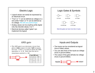
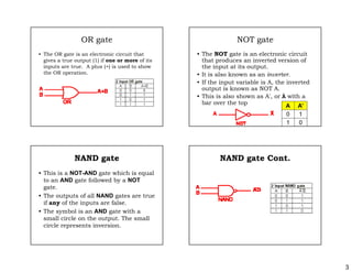
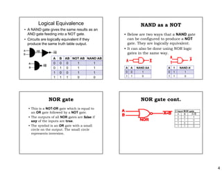
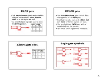
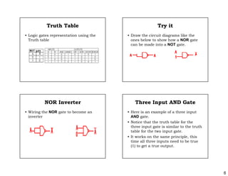
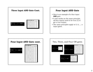
1
LOGIC GATESLOGIC GATES
COMP370
Introduction to Computer
Architecture
Introduction
• Basic Logic Gates
• Truth Tables
• Logical Functions
Truth Tables
Logical Expression
G hi l FGraphical Form
Most Difficult Reading Topics
• Logic gates and figuring out how to read
ththem
• Logical Circuit Equivalence
• NAND NOR and XOR truth tables
• Using the rules to create and read the
logic gates using 0's and 1'slogic gates using 0's and 1's
• Transistor implementation
• Difference between positive logic and
negative logic
Logic
• Formal logic is a branch of
th ti th t d lmathematics that deals
with true and false values
instead of numbers.
• In the mid-19th century, George Bool
developed many Logic ideas.developed many Logic ideas.
• Boolean logic deals with equations where
the operators are “AND” or “OR” instead of
“add” and “multiply”.
2
Electric Logic
• Logical values can easily be expressed by
l t i l i itan electrical circuit.
• “True” or “1” can be defined as voltage on a
wire while “False” or “0” can be defined as
no voltage. We will use positive logic.
• Analog values can be anything while digital• Analog values can be anything while digital
only has discrete values, 0 or 1
• Electrical devices called “gates” can
implement the logical
Logic Gates & Symbols
Note that gates can have more than 2 inputs.
AND gate
• The AND gate is an electronic circuit that
gives a true output (1) only if all its inputsgives a true output (1) only if all its inputs
are true. A dot (·) is used to show the AND
operation i.e. A·B. Note that the dot is
sometimes omitted i.e. AB
Inputs and Outputs
• The inputs can be considered as logical
(t f l ) l(true or false) values.
• You can also think of the inputs as voltage
(true) or ground (false).
• The output of the gate will also be voltage
(true) or ground (false)(true) or ground (false).
inputs output
3
OR gate
• The OR gate is an electronic circuit that
gives a true output (1) if one or more of itsgives a true output (1) if one or more of its
inputs are true. A plus (+) is used to show
the OR operation.
NOT gate
• The NOT gate is an electronic circuit
that produces an inverted version ofthat produces an inverted version of
the input at its output.
• It is also known as an inverter.
• If the input variable is A, the inverted
output is known as NOT A.
• This is also shown as A', or Ā with a
bar over the top
A A’
0 1
1 0
NAND gate
• This is a NOT-AND gate which is equal
t AND t f ll d b NOTto an AND gate followed by a NOT
gate.
• The outputs of all NAND gates are true
if any of the inputs are false.
• The symbol is an AND gate with a• The symbol is an AND gate with a
small circle on the output. The small
circle represents inversion.
NAND gate Cont.
4
Logical Equivalence
• A NAND gate gives the same results as an
AND gate feeding into a NOT gate.
• Circuits are logically equivalent if they
produce the same truth table output.
A B AB NOT AB NAND ABA B AB NOT AB NAND AB
0 0 0 1 1
0 1 0 1 1
1 0 0 1 1
1 1 1 0 0
NAND as a NOT
• Below are two ways that a NAND gate
b fi d t d NOTcan be configured to produce a NOT
gate. They are logically equivalent.
• It can also be done using NOR logic
gates in the same way.
A A NAND AA
0 0 1
1 1 0
A 1 NAND A’
0 1 1
1 1 0
NOR gate
• This is a NOT-OR gate which is equal to
an OR gate followed by a NOT gatean OR gate followed by a NOT gate.
• The outputs of all NOR gates are false if
any of the inputs are true.
• The symbol is an OR gate with a small
circle on the output. The small circle
represents inversionrepresents inversion.
NOR gate cont.
5
EXOR gate
• The 'Exclusive-OR' gate is a circuit which
ill i t t t if ith b t twill give a true output if either, but not
both, of its two inputs are true.
• An encircled plus sign ( ) is used to show
the EOR operation.
EXNOR gate
• The 'Exclusive-NOR' gate circuit does
th it t th EOR tthe opposite to the EOR gate.
• It will give a false output if either, but
not both, of its two inputs are true.
• The symbol is an EXOR gate with a
small circle on the outputsmall circle on the output.
• The small circle represents inversion.
EXNOR gate cont.
Logic gate symbols
6
Truth Table
• Logic gates representation using the
T th t blTruth table
Try it
• Draw the circuit diagrams like the
b l t h h NOR tones below to show how a NOR gate
can be made into a NOT gate.
NOR Inverter
• Wiring the NOR gate to become an
i tinverter
Three Input AND Gate
• Here is an example of a three input
AND tAND gate.
• Notice that the truth table for the
three input gate is similar to the truth
table for the two input gate.
• It works on the same principle this• It works on the same principle, this
time all three inputs need to be true
(1) to get a true output.
7
Three Input AND Gate Cont. Four Input AND Gate
• Here is an example of a four input
AND tAND gate.
• It also works on the same principle,
all four inputs need to be true (1) to
get a true output.
• The same principles apply to 5 6 n• The same principles apply to 5, 6,..., n
input gates.
Four Input AND Gate cont. Two, Three, and Four OR gates
8
Connecting Gates
• The output of one logic gate can be used
th i t t th l i tas the input to another logic gate.
• The output of one gate can be used as the
inputs to several other gates.

Logic gates

  • 1.
    1 LOGIC GATESLOGIC GATES COMP370 Introductionto Computer Architecture Introduction • Basic Logic Gates • Truth Tables • Logical Functions Truth Tables Logical Expression G hi l FGraphical Form Most Difficult Reading Topics • Logic gates and figuring out how to read ththem • Logical Circuit Equivalence • NAND NOR and XOR truth tables • Using the rules to create and read the logic gates using 0's and 1'slogic gates using 0's and 1's • Transistor implementation • Difference between positive logic and negative logic Logic • Formal logic is a branch of th ti th t d lmathematics that deals with true and false values instead of numbers. • In the mid-19th century, George Bool developed many Logic ideas.developed many Logic ideas. • Boolean logic deals with equations where the operators are “AND” or “OR” instead of “add” and “multiply”.
  • 2.
    2 Electric Logic • Logicalvalues can easily be expressed by l t i l i itan electrical circuit. • “True” or “1” can be defined as voltage on a wire while “False” or “0” can be defined as no voltage. We will use positive logic. • Analog values can be anything while digital• Analog values can be anything while digital only has discrete values, 0 or 1 • Electrical devices called “gates” can implement the logical Logic Gates & Symbols Note that gates can have more than 2 inputs. AND gate • The AND gate is an electronic circuit that gives a true output (1) only if all its inputsgives a true output (1) only if all its inputs are true. A dot (·) is used to show the AND operation i.e. A·B. Note that the dot is sometimes omitted i.e. AB Inputs and Outputs • The inputs can be considered as logical (t f l ) l(true or false) values. • You can also think of the inputs as voltage (true) or ground (false). • The output of the gate will also be voltage (true) or ground (false)(true) or ground (false). inputs output
  • 3.
    3 OR gate • TheOR gate is an electronic circuit that gives a true output (1) if one or more of itsgives a true output (1) if one or more of its inputs are true. A plus (+) is used to show the OR operation. NOT gate • The NOT gate is an electronic circuit that produces an inverted version ofthat produces an inverted version of the input at its output. • It is also known as an inverter. • If the input variable is A, the inverted output is known as NOT A. • This is also shown as A', or Ā with a bar over the top A A’ 0 1 1 0 NAND gate • This is a NOT-AND gate which is equal t AND t f ll d b NOTto an AND gate followed by a NOT gate. • The outputs of all NAND gates are true if any of the inputs are false. • The symbol is an AND gate with a• The symbol is an AND gate with a small circle on the output. The small circle represents inversion. NAND gate Cont.
  • 4.
    4 Logical Equivalence • ANAND gate gives the same results as an AND gate feeding into a NOT gate. • Circuits are logically equivalent if they produce the same truth table output. A B AB NOT AB NAND ABA B AB NOT AB NAND AB 0 0 0 1 1 0 1 0 1 1 1 0 0 1 1 1 1 1 0 0 NAND as a NOT • Below are two ways that a NAND gate b fi d t d NOTcan be configured to produce a NOT gate. They are logically equivalent. • It can also be done using NOR logic gates in the same way. A A NAND AA 0 0 1 1 1 0 A 1 NAND A’ 0 1 1 1 1 0 NOR gate • This is a NOT-OR gate which is equal to an OR gate followed by a NOT gatean OR gate followed by a NOT gate. • The outputs of all NOR gates are false if any of the inputs are true. • The symbol is an OR gate with a small circle on the output. The small circle represents inversionrepresents inversion. NOR gate cont.
  • 5.
    5 EXOR gate • The'Exclusive-OR' gate is a circuit which ill i t t t if ith b t twill give a true output if either, but not both, of its two inputs are true. • An encircled plus sign ( ) is used to show the EOR operation. EXNOR gate • The 'Exclusive-NOR' gate circuit does th it t th EOR tthe opposite to the EOR gate. • It will give a false output if either, but not both, of its two inputs are true. • The symbol is an EXOR gate with a small circle on the outputsmall circle on the output. • The small circle represents inversion. EXNOR gate cont. Logic gate symbols
  • 6.
    6 Truth Table • Logicgates representation using the T th t blTruth table Try it • Draw the circuit diagrams like the b l t h h NOR tones below to show how a NOR gate can be made into a NOT gate. NOR Inverter • Wiring the NOR gate to become an i tinverter Three Input AND Gate • Here is an example of a three input AND tAND gate. • Notice that the truth table for the three input gate is similar to the truth table for the two input gate. • It works on the same principle this• It works on the same principle, this time all three inputs need to be true (1) to get a true output.
  • 7.
    7 Three Input ANDGate Cont. Four Input AND Gate • Here is an example of a four input AND tAND gate. • It also works on the same principle, all four inputs need to be true (1) to get a true output. • The same principles apply to 5 6 n• The same principles apply to 5, 6,..., n input gates. Four Input AND Gate cont. Two, Three, and Four OR gates
  • 8.
    8 Connecting Gates • Theoutput of one logic gate can be used th i t t th l i tas the input to another logic gate. • The output of one gate can be used as the inputs to several other gates.