
Recommended
Recommended
More Related Content
What's hot
What's hot (20)
Similar to LIEBHERR RL64 PIPE LAYER SERIES 4 LITRONIC Service Repair Manual
Similar to LIEBHERR RL64 PIPE LAYER SERIES 4 LITRONIC Service Repair Manual (19)
Recently uploaded
Recently uploaded (20)
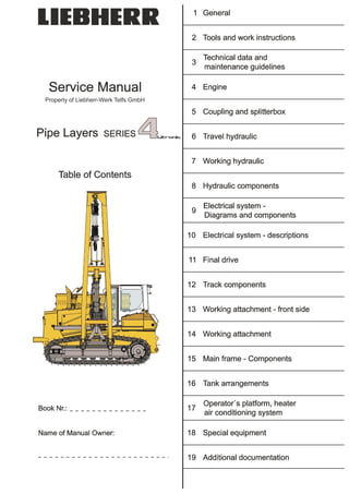
LIEBHERR RL64 PIPE LAYER SERIES 4 LITRONIC Service Repair Manual
- 1.
- 2. Service Manual Index RL Litronic Serie 4 MJFCIFSS! 0.1.00 - 1 / 4 LWT/Ausgabe/Edition/Edition/03.2010 0.1.00 Index Section Title Date of issue 0.1.00 Index 03.2010 1.0.00 Sub group index "General" 01.2008 1.1.00 Foreword and explanation 01.2008 1.2.00 Safety regulations 05.2008 Charts 1.3.01 Tightening torques 05.2008 1.3.02 Conversion tables 01.2009 1.3.03 Tapping holes 01.2008 1.4.00 Conservation guidelines 02.2010 1.5.00 Material weights 03.2009 2.0.00 Sub group index "Tools and work instructions" 01.2008 2.1.00 Special tools 03.2010 2.2.00 Repair welding 03.2010 2.3.00 Installation instructions 03.2010 3.0.00 Sub group index "Technical data and maintenance guidelines" 01.2008 3.1.40 Technical data 06.2008 3.1.60 Technical data 06.2008 3.2.00 Maintenance and inspection schedule 03.2010 3.3.00 Maintenance and inspection instructions 03.2009 3.4.40 Adjustment checklist 03.2010 3.4.60 Adjustment checklist 03.2010 3.5.00 Test and adjustment tasks 03.2010 4.0.00 Sub group index "Engine" 01.2008 4.1.40 Data page 01.2008 4.1.60 Data page 05.2008 4.2.00 Fan and cylinder arrangement 05.2008 5.0.00 Sub group index "Coupling and splitterbox" 01.2008 5.1.00 Data page 05.2008 5.2.40 Coupling 05.2008 5.2.60 Coupling 05.2008 5.3.40 Pump distributor gear 01.2008 5.3.60 Pump distributor gear 05.2008 5.4.40 Coupling Pump output 05.2008 5.4.60 Coupling Pump output 06.2008 6.0.00 Sub group index "Travel hydraulic" 01.2008 6.1.00 Data page 05.2008 6.2.40 Design 06.2008 6.2.60 Design 06.2008 6.3.40 Function 01.2009 6.3.60 Function 01.2009 6.4.00 Repair work and troubleshooting 05.2008 6.5.40 Component arrangement 01.2008 6.5.60 Component arrangement 05.2008 copyright by
- 3. Service Manual Index RL Litronic Serie 40.1.00 - 2 / 4 Mjfcifss! LWT/Ausgabe/Edition/Edition/03.2010 Section Title Date of issue 7.0.00 Sub group index "Working hydraulic" 01.2008 7.1.00 Data page 05.2008 7.2.00 Design 05.2008 7.3.00 Function 02.2010 7.4.00 Repair work and troubleshooting 05.2008 7.5.40 Component arrangement 01.2008 7.5.60 Component arrangement 05.2008 8.0.00 Sub group index "Hydraulic components" 01.2008 8.1.40 Var. displacement pump 01.2008 8.1.60 Var. displacement pump 01.2009 8.2.40 Var. displacement motor 01.2008 8.2.60 Var. displacement motor 05.2008 8.3.00 Regulating pump – Working hydraulic 05.2008 8.4.40 Double gear pump – replenishing / fan drive 05.2008 8.4.60 Double gear pump – replenishing 05.2008 8.5.40 Gear motor – fan drive 05.2008 8.5.60 Gear motor – fan drive 05.2008 8.6.00 Pilot control – working hydraulic 01.2008 8.7.00 Control valve block 05.2008 8.8.00 Valves 02.2009 8.9.00 Hydraulic cylinder 05.2008 8.10.00 Control motor hoist gear – winch 05.2008 9.0.00 Sub group index "Electrical system – Diagrams and components" 05.2008 9.1.40 Wiring diagram, component description, function list 01.2010 9.1.41 Wiring diagram, component description, function list 01.2010 9.1.60 Wiring diagram, component description, function list 01.2010 9.1.61 Wiring diagram, component description, function list 01.2010 9.2.00 Instrument panel 05.2008 9.3.40 Component arrangement 02.2010 9.3.60 Component arrangement 02.2010 9.4.00 Joystick 02.2010 9.5.00 Inching- / brake pedal 02.2009 10.0.00 Sub group index "Electrical system - descriptions" 01.2009 10.1.00 Diagnostics software LinDiag 01.2010 10.2.00 Software PDL – Diesel particle filter 01.2010 11.0.00 Sub group index "Final drive" 01.2008 11.1.40 Data page 05.2008 11.1.60 Data page 05.2008 11.2.40 Design and Function 01.2008 11.2.60 Design and Function 05.2008 11.3.40 Sectional view - final drive 01.2008 11.3.60 Sectional view - final drive 01.2009 copyright by
- 4. Service Manual Index RL Litronic Serie 4 MJFCIFSS! 0.1.00 - 3 / 4 LWT/Ausgabe/Edition/Edition/03.2010 Section Title Date of issue 12.0.00 Sub group index "Track components" 01.2008 12.1.00 Data page 05.2008 12.2.00 Design, function, wear and evaluation 01.2008 12.3.00 Test report 01.2010 12.3.01 Wear chart 01.2009 12.4.40 Track roller frame and idler unit 05.2008 12.4.60 Track roller frame and idler unit 03.2010 12.5.00 Track roller 01.2008 12.6.00 Carrier roller 01.2008 12.7.40 Tension unit 06.2008 12.7.60 Tension unit 06.2008 13.0.00 Sub group index "Working attachment – front side" 01.2008 14.0.00 Sub group index "Working attachment" 01.2008 14.1.00 Hoist gear 05.2008 14.2.00 Rope winch 02.2009 15.0.00 Sub group index "Main frame – Components" 01.2008 15.1.40 Cooler arrangement 01.2008 15.1.60 Cooler arrangement 05.2008 15.2.40 Equalizer bar 01.2008 15.2.60 Equalizer bar 05.2008 15.3.40 Engine mounting 01.2008 15.3.60 Engine mounting 05.2008 16.0.00 Sub group index "Tank arrangements" 01.2008 16.1.40 Hydraulic tank 05.2008 16.1.60 Hydraulic tank 05.2008 16.2.40 Fuel tank 01.2008 16.2.60 Fuel tank 05.2008 16.3.40 Battery compartment 01.2008 16.3.60 Battery compartment 02.2009 17.0.00 Sub group index "Operator’s platform, heater, air conditioning system" 01.2008 17.1.00 Operator’s platform 01.2008 17.2.00 Heater with blower 01.2008 17.3.00 Air conditioning system 01.2008 17.4.00 Operator’s seat – air cushioned 01.2008 17.5.00 Throttle control 05.2008 18.0.00 Sub group index "Special equipment" 01.2009 18.1.00 Refueling pump 03.2009 18.3.00 Add-on installations – Pipe chamfering device and welding generator 01.2009 copyright by
- 5. Service Manual Index RL Litronic Serie 40.1.00 - 4 / 4 Mjfcifss! LWT/Ausgabe/Edition/Edition/03.2010 Section Title Date of issue 19.0.00 Sub group index "Additional documentation" 01.2008 6.3.40 Schematic – Travel hydraulic 05.2008 6.3.60 Schematics – Travel hydraulic 05.2008 7.3.40 Schematic – Working hydraulic 02.2010 7.3.60 Schematic – Working hydraulic 02.2010 9.1.40 Wiring diagram, component description, function list 01.2010 9.1.41 Wiring diagram, component description, function list 01.2010 9.1.60 Wiring diagram, component description, function list 01.2010 9.1.61 Wiring diagram, component description, function list 01.2010 copyright by
- 6. Service Manual General Sub group index - General RL Litronic Series 4 MJFCIFSS! 1.0.00 - 1 / 2 LWT/Ausgabe/Edition/Edition/01.2008 1 General 1.0.00 Sub group index - General Foreword and explanations ......................................................................... 1.1 Safety regulations ......................................................................................... 1.2 Charts............................................................................................................. 1.3 Tightening torques............................................................................................................1.3.01 Conversion tables.............................................................................................................1.3.02 Tapping holes ...................................................................................................................1.3.03 Conservation guidelines............................................................................... 1.4 Material weights............................................................................................. 1.5 copyright by
- 7. Service Manual General Foreword and explanation RL Litronic Series 4 MJFCIFSS! 1.1.00 - 1 / 2 LWT/Ausgabe/Edition/Edition/01.2008 1.1.00 Foreword and explanation 1 For information This manual contains technical data, design and functional descriptions, work and adjustment instructions as well as numerous drawings, functional views and illustrations for the LIEBHERR – Pipe layers (RL) of Series 4. This manual should simplify competent customer service of our products, however, it does not replace expert and qualified user training and attendance of our factory training classes. Generally valid technical basic information is not listed. Refer to separate documentation for operational and spare parts information. The manual will be updated and expanded as necessary when changes occur in series. For all tasks on the machine, accident prevention guidelines and safety guidelines must be strictly observed. This manual is solely for the own use of the registered owner and may not be duplicated or copied, complete or in part, nor passed on to a third person and remains the property of LIEBHERR-Werk Telfs GmbH. All rights reserved. – Printed in Austria. We reserve the right to make changes of technical details on the machine in comparison to the information and illustrations in this manual. Written and published by LIEBHERR-Werk Telfs GmbH., Technical Documentation Dept. copyright by
- 8. General Service Manual Foreword and explanation RL Litronic Series 41.1.00 - 2 / 2 Mjfcifss! LWT/Ausgabe/Edition/Edition/01.2008 2 Explanation of layout To simplify finding certain information and filing of updates, we set up the following layout: Main group Component (item) groups according to register Type group Structure based on information content or machine size Sub group Structure of main group according to sub group index Page number Continuous No. and complete number of pages within the type group It is possible that other continuous numbers are listed after the continuous number, for example 9.4.20 - 13/15 - 02. This number is for supplements, especially for electrical schematics, where only one page is supplemented. Changes are supplied with the same number, but with a later date, supplements are assigned a new number. If only one page is valid for a certain machine group, then this is noted in the header. Note! This symbol is used in the manual for very important safety notes. This symbol identifies a standard listing. This symbol signifies the following: “The prerequisite must be met”. The maintenance personnel must first fulfil the precondition described, i.e. the machine must be brought into a particular work position in order to be able to carry out the actions subsequently described. This symbol identifies an action. The maintenance personnel should be active at this location and carry out the action described. This symbol identifies a result. The maintenance personnel is notified that a result will occur after a working step, for example, after the test knob is pressed, the LED light lights up. This note shows that a detail view of an illustration is shown rotated by a given angle, as compared to the actual installation position. (In this case 180°) We hope that with the supplied information we have taken yet another step to improve service on the LIEBHERR crawler dozers, crawler loaders, pipe layers and telescopic handlers. LIEBHERR-Werk Telfs GmbH. Technical documentation copyright by
- 9. Service Manual General Safety guidelines RL Litronic Series 4 MJFCIFSS! 1.2.00 - 1 / 4 LWT/Ausgabe/Edition/Edition/05.2008 1.2.00 Safety guidelines 1 Introduction Prior and during the performance of tests / inspections, adjustments and repairs, it is imperative that the following safety guidelines are observed: Any type of work may only be carried out by qualified expert personnel or under their guidance and supervision. Qualified expert personnel are persons, who, based on their specialized training and experience, have sufficient knowledge in the area of earthmoving equipment and the specific technology of our machines in particular and who are familiar with all applicable laws and general work protection regulations, accident prevention guidelines, regulations, guidelines and generally approved rules concerning technology so that they are able to evaluate if the earthmoving equipment is safe to operate and if the necessary work can be performed without endangering themselves or third persons. Machines with raised operator’s platform may not be driven! The machine may only be operated from a lowered and secured operator’s platform! Always adhere to the adjustment values noted in the LIEBHERR documentation when performing adjustment work. At the delivery of a machine, the operating personnel must be trained using the current operating instructions. The safety guidelines noted in the instructions must be particularly observed. These safety guidelines must also be observed during inspection, adjustment or repair work. However, there are special repair and / or inspection work which require qualified personnel to follow another procedure than that noted in the safety guidelines. In such cases, qualified personnel or individuals performing the work under the supervision of such personnel should assure that additional safety precautions necessary to insure the safety of those involved in the repair are taken. The decision to carry out this measure can only be made by qualified expertly trained personnel. Such items of repair and/ or inspection work include, but are not limited to the following: - Opening the side doors while the Diesel engine running to carry out tests and / or adjustments. In these cases, care should be taken that the side engine compartment doors are properly secured during the entire duration of the work to prevent them from closing unexpectedly and / or inadvertently. Care should be exercised to assure that there will be no inadvertent or unintended contact of any part of the body with any moving and / or heated parts of the engine. Wear only tightly fitted clothing (no scarves, no tie, no wide sleeves, etc.) - Starting the Diesel engine with tilted operator’s platform, as well as actuating the travel drive with properly raised machine for adjustment, repair or diagnostics purposes. In these cases, before starting the engine, the support of the operator’s platform support as well as the support for the machine and the required ground clearance for the track chains must be checked again. copyright by
- 10. General Service Manual Safety guidelines RL Litronic Serie 41.2.00 - 2 / 4 Mjfcifss! LWT/Ausgabe/Edition/Edition/05.2008 2 Danger notes in this manual For description of work, which can pose a danger for man or machine, the required safety precautions are described in this manual. They are marked by the following notes: Danger! Warns that certain working procedures without appropriate precautionary measures can result in fatal injuries. Warning! Warns that certain working procedures without appropriate precautionary measures can result in severe bodily injuries. Caution! Warns that certain working procedures without appropriate precautionary measures can result in bodily injuries or damage to the machine. Following these notes does not relieve you of the responsibility for following additional rules and guidelines! Additional points that should be noted are: the safety regulations which apply on the jobsite, statutory “road traffic regulations”, the guidelines provided by professional associations. copyright by
- 11. Service Manual General Safety guidelines RL Litronic Series 4 MJFCIFSS! 1.2.00 - 3 / 4 LWT/Ausgabe/Edition/Edition/05.2008 3 Safety guidelines in the operating instructions The detailed descriptions for the following safety guidelines are noted in the operating instructions of the machine and must be strictly observed. 2.1 Introduction 2.2 Designated use 2.3 Signs on the machine 2.4 Safety guidelines 2.4.1 General safety guidelines 2.4.2 Crushing and burn prevention 2.4.3 Fire and explosion prevention 2.4.4 Safety guidelines for machine start up 2.4.5 Engine start up safety 2.4.6 Machine operating safety 2.4.7 Safety guidelines for working with the machine 2.4.8 Working in the vicinity of electrical overhead lines 2.4.9 Machine parking safety 2.4.10 Machine transporting safety 2.4.11 Machine towing safety 2.4.12 Machine maintenance safety 2.4.13 Safety guidelines for welding work on the machine 2.4.14 Safety guidelines for working on the attachment 2.4.15 Safety guidelines when loading the machine with a crane 2.4.16 Safe maintenance of hydraulic hoses and hose lines 2.4.17 Safety guidelines for maintenance work on machines with hydro accumulators 2.4.18 Roll over protection (ROPS) and falling object protection (FOPS) 2.4.19 Equipment and attachment parts 2.4.20 Protection from vibrations copyright by
- 12. Service Manual General Tightening torques RL Litronic Series 4 MJFCIFSS! 1.3.01 - 1 / 4 LWT/Ausgabe/Edition/Edition/05.2008 1.3.01 Tightening torques 1 General information The preload values and the tightening torques noted in the chart have been taken from the VDI (Association of German Engineers) guidelines 2230 of July 1986. Installation preload values FM and tightening torques MA for shoulder studs with standard metric or fine thread per DIN ISO 262 and DIN ISO 965 T2 (replacement for DIN 13 part 13) and wrench sizes for hex head screws with shaft DIN EN 24014 (replacement for DIN 931 part 1) or socket head screws DIN EN ISO 4762 (replacement for DIN 912) The chart values are valid for screws with surface: - black or phosphated – oiled - zinc plated – oiled - flZn according to LH standard 10021432 - dry (replaces DACROMET 500). Medium friction value G = 0.12 Note! Any tightening torque values and/ or tightening procedures noted in drawings / parts lists, instructions or component descriptions must be adhered to and given preference over factory standards. Beginning with grade 10.9, no additional safety effect is provided when using lock washers Always use correctly sized torque wrenches – the torque value according to the chart should be within the upper third of the existing range. When using impact wrenches, care must be taken so that the torque values are not exceeded. Check before and intermediately with a torque wrench. Note! The tightening torques for the following components are noted in the following sections in detail: Hydraulic cylinder – see section 8.9. Track pad and sprocket segment screws – see section 12.1. Rope winch – see section 14.2. copyright by
- 13. General Service Manual Tightening torques RL Litronic Series 41.3.01 - 2 / 4 Mjfcifss! LWT/Ausgabe/Edition/Edition/05.2008 2 Preload values and tightening torques for screws with standard metric thread according to factory standard WN 4037 I Wrench size (x) = according to DIN931, for Preload value Fm based on grades in N Tightening torques Ma based on grades in Nm Hex head screw Socket head screw Metric standard thread 8.8 10.9 12.9 8.8 10.9 12.9 mm Inch mm Inch M 4 x 0.7 4050 6000 7000 2,8 4,1 4,8 7 9/32 3 - - M 5 x 0.8 6600 9700 11400 5,5 8,1 9,5 8 5/16 4 5/32 M 6 x 1 9400 13700 16100 9,5 14 16,5 10 - - 5 - - M 7 x 1 13700 20100 23500 15,5 23 27 11 - - - - - - M 8 x 1.25 17200 25000 29500 23 34 40 13 1/2 6 - - M 10 x 1.5 27500 40000 47000 46 68 79 (17) 16 (11/16)-- 8 5/16 M 12 x 1.75 40000 59000 69000 79 117 135 (19) 18 (3/4) - - 10 - - M 14 x 2 55000 80000 94000 125 185 215 (22) 21 (7/8) - - 12 - - M 16 x 2 75000 111000 130000 195 280 330 24 - - 14 9/16 M 18 x 2.5 94000 135000 157000 280 390 460 27 1-1/16 14 9/16 M 20 x 2.5 121000 173000 202000 390 560 650 30 1-3/16 17 - - M 22 x 2.5 152000 216000 250000 530 750 880 (32) 34 - - 17 - - M 24 x 3 175000 249000 290000 670 960 1120 36 1-7/16 19 3/4 M 27 x 3 230000 330000 385000 1000 1400 1650 41 1-5/8 19 3/4 M 30 x 3.5 280000 400000 465000 1350 1900 2250 46 1-13/16 22 7/8 M 33 x 3.5 350000 495000 580000 1850 2600 3000 50 2 24 - - M 36 x 4 410000 580000 680000 2350 3300 3900 55 2-3/16 27 1-1/16 M 39 x 4 490000 700000 820000 3000 4300 5100 60 2-3/8 27 1-1/16 copyright by
- 14. Service Manual General Tightening torques RL Litronic Series 4 MJFCIFSS! 1.3.01 - 3 / 4 LWT/Ausgabe/Edition/Edition/05.2008 3 Preload values and tightening torques for screws with fine metric thread according to factory standard WN 4037 I Wrench size (x) = according to DIN931, for Preload value Fm based on grades in N Tightening torques Ma based on grades in Nm Hex head screw Socket head screw Metric standard thread 8.8 10.9 12.9 8.8 10.9 12.9 mm Inch mm Inch M 8 x 1 18800 27500 32500 24,5 36 43 13 1/2 6 - - M 9 x 1 24800 36500 42500 36 53 62 - - - - - - - - M 10 x 1 31500 46500 54000 52 76 89 17 11/16 8 5/16 M 10 x 1.25 29500 43000 51000 49 72 84 17 11/16 8 5/16 M 12 x 1.25 45000 66000 77000 87 125 150 19 3/4 10 - - M 12 x 1.5 42500 62000 73000 83 122 145 19 3/4 10 - - M 14 x 1.5 61000 89000 104000 135 200 235 22 7/8 12 - - M 16 x 1.5 82000 121000 141000 205 300 360 24 - - 14 9/16 M 18 x 1.5 110000 157000 184000 310 440 520 27 1-1/16 14 9/16 M 18 x 2 102000 146000 170000 290 420 490 27 1-1/16 14 9/16 M 20 x 1.5 139000 199000 232000 430 620 720 30 1-3/16 17 - - M 22 x 1.5 171000 245000 285000 580 820 960 32 - - 17 - - M 24 x 1.5 207000 295000 346000 760 1090 1270 36 1-7/16 19 3/4 M 24 x 2 196000 280000 325000 730 1040 1220 36 1-7/16 19 3/4 M 27 x 1.5 267000 381000 445000 1110 1580 1850 41 1-5/8 19 3/4 M 27 x 2 255000 365000 425000 1070 1500 1800 41 1-5/8 19 3/4 M 30 x 1.5 335000 477000 558000 1540 2190 2560 46 1-13/16 22 7/8 M 30 x 2 321000 457000 534000 1490 2120 2480 46 1-13/16 22 7/8 M 33 x 1.5 410000 584000 683000 2050 2920 3420 50 2 24 - - M 33 x 2 395000 560000 660000 2000 2800 3300 50 2 24 - - M 36 x 1.5 492000 701000 820000 2680 3820 4470 55 2-3/16 27 1-1/16 M 36 x 3 440000 630000 740000 2500 3500 4100 55 2-3/16 27 1-1/16 M 39 x 1.5 582000 830000 971000 3430 4890 5720 60 2-3/8 27 1-1/16 M 39 x 3 530000 750000 880000 3200 4600 5300 60 2-3/8 27 1-1/16 copyright by
- 15. General Service Manual Tightening torques RL Litronic Series 41.3.01 - 4 / 4 Mjfcifss! LWT/Ausgabe/Edition/Edition/05.2008 4 Tightening torques for screws to mount SAE flange Note! Not part of factory standard WN 4037 I Listing according to LFR – Quality service 2QA 6 051 00 as of Oct. 2001 4.1 Flanges and half flanges for high pressure (Norm 62) Tightening torques in Nm for screw grade 10.9 Flange nominal size Screw size Half flange Flat flange without reinforcement rim Flange with reinforcement rim ½" M 8 31 -- -- ¾" M 10 62 45 65 1" M 12 108 70 110 1 ¼" M 14 172 120 180 1 ½" M 16 264 170 250 2" M 20 350 250 450 4.2 Half flange for low pressure (Norm 61) Tightening torques in Nm for Flange nominal size Screw size Screw grade 8.8 Screw grade 10.9 ½" M 8 22 31 ¾" M 10 44 62 1" M 10 44 62 1 ¼" M 10 44 62 1 ½" M 12 76 108 2" M 12 76 108 2 ½" M 12 76 108 3" M 14 122 172 3 ½" M 16 187 264 4" M 16 187 264 5" M 16 187 264 copyright by
- 16. Service Manual General Conversion chart RL Litronic Series 4 MJFCIFSS! 1.3.02 - 1 / 2 LWT/Ausgabe/Edition/Edition/01.2009 1.3.02 Conversion chart Size from unit Multiplier to unit from Multiplier to unit Length mm 0,039 inch 25,4 mm m 3,281 feet 0,305 m m 1,093 yard 0,914 m km 0,621 mile 1,609 km Area cm² 0,155 sq. inch 6,452 cm² m² 10,764 sq. feet 0,093 m² m² 1,196 sq. yard 0,863 m² km² 0,386 sq. mile 2,59 km² Volume cm³ 0,061 cu. inch 16,387 cm³ m³ 35,314 cu. feet 0,028 m³ m³ 1,308 cu. yard 0,764 m³ l 61,025 cu. inch l l 0,035 cu. feet 28,316 l l 0,264 gallon 3,785 l l 1,057 quart 0,946 l Mass g 0,035 oz. 28,349 g kg 2,204 lbs. 0,453 kg t 1,102 short t 0,907 t Force N 0,225 lbs. 4,449 N kN 224,732 lbs. 0,0044 kN Torque Nm 0,737 ft. lbs. 1,356 Nm Performance kW 1,342 HP 0,745 kW PS 0,736 kW 1,358 PS Pressure bar 14,5 PSI 0,069 bar (hydraulic) kpa 0,145 PSI 6,896 kpa Ground pressure kg/cm² 14,223 lbs.inch2 0,0703 kg/cm² kg/m² 0,205 lbs. ft.2 4,878 kg/m² Density g/cm³ 0,036 lbs. inch 3 27,78 g/cm³ kg/m³ 0,062 lbs. ft.3 16,13 kg/m³ Speed km/h 0,621 Mph 1,609 km/h m/min 3,281 ft. / min 0,305 m/min Temperature °C (°Cx1,8) + 32 °F (°F-32)/1,8 °C °C °C+273 °K °K-273 °C copyright by
- 17. General Service Manual Conversion chart RL Litronic Series 41.3.02 - 2 / 2 Mjfcifss! LWT/Ausgabe/Edition/Edition/01.2009 copyright by
- 18. Service Manual General Tapping holes RL Litronic Series 4 MJFCIFSS! 1.3.03 - 1 / 2 LWT/Ausgabe/Edition/Edition/01.2008 1.3.03 Tapping holes 1 Tapping holes for metric ISO standard threads Thread Hole diameter Ø Diameter dimensions max. min. Drill bit Ø M 1 0,785 0,729 0,75 M 1,1 0,885 0,829 0,85 M 1,2 0,985 0,929 0,95 M 1,4 1,160 1,075 1,1 M 1,6 1,321 1,221 1,25 M 1,7 1,346 1,258 1,30 M 1,8 1,521 1,421 1,45 M 2 1,679 1,567 1,6 M 2,2 1,838 1,713 1,75 M 2,3 1,920 1,795 1,9 M 2,5 2,138 2,013 2,05 M 2,6 2,176 2,036 2,10 M 3 2,599 2,459 2,5 M 3,5 3,010 2,850 2,9 M 4 3,422 3,242 3,3 M 4,5 3,878 3,688 3,7 M 5 4,334 4,134 4,2 M 6 5,153 4,917 5 M 7 6,153 5,917 6 M 8 6,912 6,647 6,8 M 9 7,912 7,647 7,8 M 10 8,676 8,376 8,5 M 11 9,676 9,376 9,6 M 12 10,441 10,106 10,2 M 14 12,210 11,835 12 M 16 14,210 13,835 14 M 18 15,744 15,294 15,5 M 20 17,744 17,294 17,5 M 22 19,744 19,294 19,5 M 24 21,252 20,752 21 M 27 24,252 23,752 24 M 30 26,771 26,211 26,5 M 33 29,771 29,211 29,5 M 36 32,270 31,650 32 M 39 35,270 34,670 35 M 42 37,799 39,129 37,5 M 45 40,799 40,129 40,5 M 48 43,297 42,587 43,0 M 52 47,297 46,587 47,0 M 56 50,796 50,046 50,5 M 60 54,796 54,046 54,1 M 64 58,305 57,505 57,6 M 68 62,305 61,505 61,6 copyright by
- 19. General Service Manual Tapping holes RL Litronic Series 41.3.03 - 2 / 2 Mjfcifss! LWT/Ausgabe/Edition/Edition/01.2008 2 Tapping holes for metric ISO fine threads Thread size Hole Ø diameter limits max. min. Drill bit Ø Thread size Hole Ø diameter limits max. min. Drill bit Ø M 1 x 0,2 0,821 0,783 0,8 M 25 x 1 24,153 23,917 24 M 1,1 x 0,2 0,921 0,833 0,9 M 25 x 1,5 23,676 23,376 23,5 M 1,2 x 0,2 1,021 0,983 1 M 25 x 2 23,210 22,835 23 M 1,4 x 0,2 1,221 1,183 1,2 M 26 x 1,5 24,676 24,376 24,5 M 1,4 x 0,25 1,185 1,129 1,15 M 27 x 1 26,153 25,917 26 M 1,6 x 0,2 1,421 1,383 1,4 M 27 x 1,5 25,676 25,376 25,5 M 1,8 x 0,2 1,621 1,583 1,6 M 27 x 2 25,210 24,835 25 M 2 x 0,25 1,785 1,729 1,75 M 28 x 1 27,153 26,917 27 M 2,2 x 0,25 1,985 1,929 1,95 M 28 x 1,5 26,676 26,376 26,5 M 2,5 x 0,35 2,201 1,121 2,15 M 28 x 2 26,210 25,835 26 M 3 x 0,35 2,721 2,621 2,65 M 30 x 1 29,153 28,917 29 M 3,5 x 0,35 3,221 3,121 3,15 M 30 x 1,5 28,676 28,376 28,5 M 4 x 0,5 3,599 3,459 3,5 M 30 x 2 28,210 27,835 28 M 4,5 x 0,5 4,099 3,959 4 M 30 x 3 27,252 26,752 27 M 5 x 0,5 4,599 4,459 4,5 M 32 x 1,5 30,676 30,376 30,5 M 5,5 x 0,5 5,099 4,959 5 M 32 x 2 30,210 29,835 30 M 6 x 0,75 5,378 5,188 5,2 M 33 x 1,5 31,676 31,376 31,5 M 7 x 0,75 6,378 6,188 6,2 M 33 x 2 31,210 30,835 31 M 8 x 0,75 7,378 7,188 7,2 M 33 x 3 30,252 29,752 30 M 8 x 1 7,153 6,917 7 M 35 x 1,5 33,676 33,376 33,5 M 9 x 0,75 8,378 8,188 8,2 M 36 x 1,5 34,676 34,376 34,5 M 9 x 1 8,153 7,917 8 M 36 x 2 34,210 33,835 34 M 10 x 0,75 9,378 9,188 9,2 M 36 x 3 33,252 32,752 33 M 10 x 1 9,153 8,917 9 M 38 x 1,5 36,676 36,376 36,5 M 10 x 1,25 8,912 8,647 8,8 M 39 x 1,5 37,676 37,376 37,5 M 11 x 0,75 10,378 10,188 10,2 M 39 x 2 37,210 36,835 37 M 11 x 1 10,153 9,917 10 M 39 x 3 36,252 35,752 36 M 12 x 1 11,153 10,917 11,1 M 40 x 1,5 38,676 38,376 38,5 M 12 x 1,25 10,912 10,647 10,8 M 40 x 2 38,210 37,835 38 M 12 x 1,5 10,676 10,376 10,5 M 40 x 3 37,252 36,752 37 M 14 x 1 13,153 12,917 13 M 42 x 1,5 40,676 40,376 40,5 M 14 x 1,25 12,912 112,647 12,8 M 42 x 2 40,210 39,835 40 M 14 x 1,5 12,676 12,376 12,5 M 42 x 3 39,252 38,752 39 M 15 x 1 14,153 13,917 14 M 42 x 4 38,270 37,670 38 M 15 x 1,5 13,676 13,376 13,5 M 45 x 1,5 43,676 43,376 43,5 M 16 x 1 15,153 14,917 15 M 43 x 2 43,210 42,835 43 M 16 x 1,5 14,676 14,376 14,5 M 45 x 3 42,252 41,752 42 M 17 x 1 16,153 15,917 16 M 45 x 4 41,270 40,670 41 M 17 x 1,5 15,676 15,376 15,5 M 48 x 1,5 46,676 46,376 46,5 M 18 x 1 17,153 16,917 17 M 48 x 2 46,210 45,835 46 M 18 x 1,5 16,676 16,376 16,5 M 48 x 3 45,252 44,752 45 M 18 x 2 16,210 15,835 16 M 48 x 4 44,270 43,670 44 M 20 x 1 19,153 18,917 19 M 50 x 1,5 48,676 48,376 48,5 M 20 x 1,5 18,676 18,376 18,5 M 50 x 2 48,210 47,835 48 M 20 x 2 18,210 17,835 18 M 50 x 3 47,252 46,752 47 M 22 x 1 21,153 20,917 21 M 52 x 1,5 50,676 50,376 50,5 M 22 x 1,5 20,676 20,376 20,5 M 52 x 2 50,210 49,835 50 M 22 x 2 20,210 19,835 20 M 52 x 3 49,252 48,752 49 M 24 x 1 23,153 22,917 23 M 52 x 4 48,270 47,670 48 M 24 x 1,5 22,676 22,376 22,5 M 24 x 2 22,210 21,835 22 copyright by
- 20. Service Manual General Conservation guidelines PR Litronic Serie 4 LR Litronic Serie 4 RL Litronic Serie 4 MJFCIFSS! 1.4.00 - 1 / 6 LWT/Ausgabe/Edition/Edition/02.2010 1.4.00 Conservation guidelines 1 General All parts of a construction machine are exposed to corrosion, especially when the machine is taken out of service. Corrosion can be compared to wear. However, the effects of corrosion can greatly exceed that of mechanical wear and shorten the service life of the affected parts significantly. For that reason, for longer shut down, the machines and its components must be preserved according to certain guidelines. In general, these guidelines are tiered according to the following times: Taking the machine out of service – for an unknown duration Shut down of the machine Shut down for up to 2 months Shut down for up to 12 months Shut down for longer than 12 months Return to operation The required measures are graduated depending on the different time frames. The conservation measures cannot be strictly standardized and they must be shorted or lengthened depending on the assessment of necessity (such as environmental influences). Such influences are, for example: Placement location of machine (for example in unprotected surrounding, in closed areas, protected by a roof, temperate surrounding) Type of climate (for example extreme temperatures, location in water / near the coast, etc.) Note! For conservation for sea transport, special guidelines must be observed, which are not included in these instructions. Refer to the special operating instructions. 2 Taking the machine out of service – for an unknown duration If a machine is taken out of service for a longer period of time without conservation, then it must be operated in intervals not to exceed 14 days, to prevent abnormal corrosion and its effects. Before putting the machine back into service, check all oil levels and correct them, if necessary. Always carry out the specified daily maintenance work before putting the machine back into service. In addition, carry out the time limited maintenance work according to the inspection schedule and additional Diesel engine Operating instructions no later than the specified intervals. Put the machine into operation according to the Operating instructions and operate it until the Diesel engine and the hydraulic system has reached the specified operating temperature in the hydraulic tank and in the coolant circuit. Actuate all functions of the travel, working hydraulic as well as functions of additionally installed hydraulic components and alternately operate them over a period of approx. 20 minutes. The hydraulic cylinders must be extended and retracted over their full stroke length. When turning the machine off, retract all hydraulic cylinders fully, if possible, and fill the fuel tank. If the machine is parked on soft ground, park the machine on wooden planks or similar and secure it to prevent it from rolling off. Check the batteries and remove them and recharge them, if necessary. Check the electrical contact points and grease them, if necessary. copyright by
- 21. General Service Manual Conservation guidelines PR Litronic Serie 4 LR Litronic Serie 41.4.00 - 2 / 6 Mjfcifss! RL Litronic Serie 4 LWT/Ausgabe/Edition/Edition/02.2010 3 Shut down of the machine Preparations for shut down Park the machine on horizontal, dry and solid ground and secure it to prevent it from rolling off. Lower the working attachment to the ground level so that there is no longer any residual pressure of the hydraulic. Clean the machine diligently according to the procedure outlined in the Operating instructions. The machine must be completely dry before starting the conservation measures. Dry electronic components and damp areas on the machine with pressurized air. If freezing temperatures are expected for the intended duration of shut down, then the fuel tank must be filled with winter fuel. Then start the Diesel engine and let it run for some time to bring the winter fuel into the fuel circuit. Then add enough fuel to the fuel tank until it is full. Note! When a conserved machine is moved for loading or transport, then the conservation protection on the piston rods of the cylinders will most often be removed by the scraper ring. For that reason, if the machine is transported, the conservation of the piston rods must be rechecked after loading and carried out again, if necessary. Note! Despite completed conservations measures, the machine must still be inspected in certain intervals and touched up, if necessary. This is within left to the discretion of the operator, but these inspections should be carried out regularly (monthly), especially in aggravated conditions (cold, heat, near the coast, etc.). 3.1 Shut down for up to 2 months Required tools / Service items Description Id. No. Description Display Optical charge tester See section 2.1 To check the battery condition and the antifreeze in the coolant WAXOYL 120-4 Anti corrosion wax 8504472 Spray can 500ml Long term protection for up to 2 years Ballistol Spray Corrosion protection 10025514 Application area: Door locks Dehumidification capsule 10013313 Prevents infiltration of moisture over an extended period of time Check the entire machine for damage and remedy, if necessary. Check the machine for paint damage and remedy, if necessary. Take care of any maintenance work which would fall within the timeframe of the planned shut down. Due to the UV exposure of the components, synthetic materials, such as plastic parts, hoses, rubber etc. must be covered with suitable aids. Electrical components, contact points and plug connections which are not sealed must be sealed with conservation wax „Waxoyl 120-4“. copyright by
- 22. Service Manual General Conservation guidelines PR Litronic Serie 4 LR Litronic Serie 4 RL Litronic Serie 4 MJFCIFSS! 1.4.00 - 3 / 6 LWT/Ausgabe/Edition/Edition/02.2010 Apply a thick layer of conservation wax „Waxoyl 120-4“ to cover ball joints, hinges, blank parts and exposed piston rods. (Do not protect ball bearings with Waxoyl!) Place a dehumidification capsule into the central electric box. Protect all door and container locks with „Ballistol Spray“. Set the battery master switch (if present) to position „0“ and then remove the batteries. Check the battery acid level and add distilled water, if necessary. Always store the batteries in a cool and dry area. Check the load current regularly every 6 weeks and recharge, if necessary. Close the exhaust outlet with an air and watertight cover. Pay attention to any additional guidelines for special components or special local conditions. 3.2 Shut down for up to 12 months Carry out all measures according to paragraph 3.1. In addition, the following is required: Clean the Diesel engine externally. Drain water from the fuel tank or condensation of the Diesel engine prefilter (see Operating instructions). Add commercially available Diesel fuel to the fuel tank until it is completely full. If the shut down is during the cold time of the year, fill the fuel dank with winter Diesel fuel (Winter Diesel fuel is suitable up to a temperature of -22°C / -7.6°F). Then start the Diesel engine and let it run for some time to bring the winter fuel into the fuel circuit. Then add enough fuel to the fuel tank until it is full. Check the coolant to ensure it has sufficient corrosion and antifreeze protection - at least 50% corrosion inhibitor antifreeze fluid (for guidelines refer to the Operating instructions). Seal the entire machine (Diesel engine, hydraulic aggregates, main frame, tank, track / axles, equalizer bar, working attachments, etc.) with preservation wax „Waxoyl 120-4“. (Amount of preservative agent: An area of approx. 5m² can be treated with one liter Waxoyl) Note! The following points must be observed when applying the corrosion inhibitor wax: Observe a drying time of 3 hours. Ambient temperature at least +15°C / 59°F. Use protective equipment (breathing protection, safety glasses, respirator, etc.). The solvents of the anti corrosion wax are flammable! (Do not smoke and avoid open flames!) Cold resistant to a temperature of -40°C / -40°F. Release the chain tension by relieving the tension cylinder (see Operating instructions). Check the machine monthly and reapply conservation protective measures if necessary. copyright by
- 23. General Service Manual Conservation guidelines PR Litronic Serie 4 LR Litronic Serie 41.4.00 - 4 / 6 Mjfcifss! RL Litronic Serie 4 LWT/Ausgabe/Edition/Edition/02.2010 3.3 Shut down for longer than 12 months Carry out all measures according to paragraph 3.1 and 3.2. In addition, the following is required: Note! If a shut down for longer than 12 months is scheduled, then contact the Service Dept. of the Diesel engine manufacturer. Close off all openings, such as air filter, exhaust pipe, vent openings on components, etc. airtight. The vent for the fuel tank (if present) must remain open for safety reasons! Rub the rubber seal of the cab and containers with talcum powder, close the doors. If the cab is not installed, cover the operator’s platform properly. If necessary, remove the operator’s seat. Cover the instrument panel and protect it. 4 Return to operation 4.1 After a shut down of 2 months Remove the dehumidification capsule from the electronic box. Check the fill levels and lubricate the machine according to the Operating instructions. Install the batteries and clean / grease the battery terminals. Open the exhaust outlet. Drain water from the fuel tank or drain any condensation of the Diesel engine prefilter (see Operating instructions). Clean anti corrosion wax from ball joints, hinges, blank parts and exposed piston rods. Put the machine back into service as outlined in the Operating instructions. Before working with the machine, check all functions of the machine and remedy and defects immediately. Carry out a thorough visual inspection on the machine. Actuate all functions of the travel, working hydraulic as well as functions of additionally installed hydraulic components and alternately operate them over a period of approx. 20 minutes. The hydraulic cylinders must be extended and retracted over their full stroke length. Observe any additional guidelines for special components or special local conditions. 4.2 After a shut down of 12 months Carry out the items according to paragraph 4.1. Take an oil sample of the hydraulic oil and send it in for analysis. Carry out the scheduled maintenance and inspection work on the machine before putting it back into service. On the Diesel engine, mechanically actuate the AGR flap (exhaust return) and the engine brake flap and check for easy movement. Grease the V-belts! Use a high pressure cleaner with steam (at least 120°C) as well as 5% additive of solvent (such as petroleum) to clean the anti corrosion wax from the machine and aggregates. (Caution when walking on surfaces, there is a danger of slipping due to the wax residue.) Check the V-belt of the Diesel engine and replace it if necessary. Carry out a Diesel engine test run: Increase the Diesel engine rpm only slowly to ¾ of the high idle rpm until the operating temperature is reached. Check the oil pressure display immediately after starting the Diesel engine. Check the vacuum display of the air filter. Adjust the chain tension to suit the application (see Operating instructions). copyright by
- 24. Service Manual General Conservation guidelines PR Litronic Serie 4 LR Litronic Serie 4 RL Litronic Serie 4 MJFCIFSS! 1.4.00 - 5 / 6 LWT/Ausgabe/Edition/Edition/02.2010 4.3 After shut down of longer than 12 months Complete all items outlined in paragraph 4.2 and 4.1. Note! After a scheduled shut down of longer than 12 months contact the Service Dept. of the Diesel engine manufacturer. Remove all covers and closures, which were installed for conservation measures. Turn the Diesel engine manually a few turns (use the turning device - flywheel – see Special tools). Start the machine and bring it to operating temperature. After the machine was brought to operating temperature, change all lube and service fluids as well as filters according to the Operating instructions Check the entire machine for function and for leaks. If necessary, carry out any time limited maintenance work at this time. copyright by
- 25. General Service Manual Conservation guidelines PR Litronic Serie 4 LR Litronic Serie 41.4.00 - 6 / 6 Mjfcifss! RL Litronic Serie 4 LWT/Ausgabe/Edition/Edition/02.2010 copyright by
- 26. Service Manual General Material weights RL Litronic Series 4 MJFCIFSS! 1.5.00 - 1 / 2 LWT/Ausgabe/Edition/Edition/03.2009 1.5.00 Material weights A spec. weight 1) in kg/m3 solid B Loosening in % C Loosening facttor D spec. weight kg/m3 loose Material A B C D Anthracite coal - raw 1600 35 0,74 1190 - washed - 35 0,74 1100 Ash bituminous coal 590 - 890 8 0,93 550 - 830 Basalt 2970 52 0,66 1960 Bauxite, Kaolin 1900 33 0,75 1420 Bituminous coal - raw 1280 35 0,74 950 - washed - 35 0,74 830 Carnotite, Uranium ore 2200 35 0,74 1630 Soil - dry hardened 1900 26 0,79 1510 - wet loosened 2020 26 0,79 1600 - clay 1540 23 0,81 1250 Gypsum - broken 3170 75 0,57 1810 - ground 2790 75 0,57 1660 Granite - broken 2730 64 0,61 1660 Hematite, iron ore 2130 - 2900 18 0,85 1810 - 2450 Limestone - broken 2610 69 0,59 1540 - ground - - - 1540 Gravel - damp 2170 12 0,89 1930 - dry 1690 12 0,89 1510 - dry 6-50mm 1900 12 0,89 1690 - wet 6-50mm 2260 12 0,89 2020 Coke 860 54 0,65 1560 Loam, clay - seasoned 2020 22 0,82 1660 - dry 1840 24 0,80 1480 - wet 2080 24 0,80 1660 Clay with gravel - dry 1660 17 0,86 1420 - wet 1840 19 0,84 2540 Magnetite, iron ore 3260 17 0,86 2790 Topsoil 1370 44 0,69 950 Natural stone - ground 2670 67 0,60 1600 Pyrite, iron ore 3030 18 0,85 2580 Sand - dry, lose 1600 12 0,89 1420 - damp 1900 12 0,89 1690 - wet 2080 13 0,88 1840 Sand with clay - lose 2020 26 0,79 1600 - compressed - - - 2400 Sand with gravel - dry 1930 12 0,89 1720 - wet 2230 10 0,91 2020 Sandstone 2520 67 0,60 1510 Slate 1660 33 0,75 1250 Slag - broken 2940 68 0,59 1750 Snow - dry - - - 130 - wet - - - 520 Trapp rock - broken 2610 49 0,67 1750 copyright by
- 27. General Service Manual Material weights RL Litronic Series 41.5.00 - 2 / 2 Mjfcifss! LWT/Ausgabe/Edition/Edition/03.2009 The actual values depend on the moisture content, the grain size and the compression. Testing is required to determine more exact values. Material A B C D Weathered rock 75% rock, 25% soil 2790 42 0,70 1960 Weathered rock 50% rock, 50% Soil 2280 33 0,75 1720 Weathered rock 25% rock, 75% Soil 1960 24 0,80 1570 copyright by
- 28. Service Manual Tools and work instructions Sub group index -Tools and work instructions RL Litronic Series 4 MJFCIFSS! 2.0.00 - 1 / 2 LWT/Ausgabe/Edition/Edition/01.2008 2 Tools and work instructions 2.0.00 Sub group index -Tools and work instructions Special tools .................................................................................................. 2.1 Repair welding............................................................................................... 2.2 Installation instructions ............................................................................... 2.3 copyright by
- 29. Tools and work instructions Service Manual Sub group index -Tools and work instructions RL Litronic Series 42.0.00 - 2 / 2 Mjfcifss! LWT/Ausgabe/Edition/Edition/01.2008 copyright by
- 30. Service Manual Tools and work instructions Special tools PR Litronic Series 4 LR Litronic Series 4 RL Litronic Series 4 MJFCIFSS! 2.1.00 - 1 / 22 LWT/Ausgabe/Edition/Edition/03.2010 2.1.00 Special tools General The following section is divided into three sections: 1 Special tools - Maintenance 2 Special tools - Repairs 3 Special tools for in-house manufacture Special tools for maintenance are a must-have to carry out the maintenance and inspection schedule. In addition, some tools are necessary aids for troubleshooting. Special tools for repairs are only required in case of a repair of the affected components. Special tools for in-house manufacture can be made in-house as necessary. The drawings to make them are made available by the manufacturer. 1 Special tools Maintenance 1.1 Diesel engine Description Id. No. M-Type Remarks Illustration Sculi – Diagnostics software - accessory consisting of: LR Series 4 RL Series 4 PR 724 F/Nxxx- 9200 PR 734 F/Nxxx- 8220 PR 744 F/Nxxx- 7356 PR 754 F/Nxxx- 6924 Sculi License with USB Dongle for engine Service Level (LH ECU UPCR-, DC4-, DC5- engine control units and Master 4 – controls) 10450054 PR 764 F/Nxxx- 6888 LR Series 4 RL Series 4 PR 724 F/Nxxx- 9200 PR 734 F/Nxxx- 8220 PR 744 F/Nxxx- 7356 PR 754 F/Nxxx- 6924 Communication cable for LH-ECU-UPCR – control units 10035410 PR 764 F/Nxxx- 9506 Communication cable for DC4 / DC5 – control units 10035411 PR 764 F/Nxxx- 6888 9505 Diagnostics software for maintenance and adjustment of Diesel engine. For ordering, a Liebherr form from Liebherr Bulle must be filled out. Download the current software version with the aid of the Lidos DVD. Use of Sculi software also possible with the previous DC-Desk Dongle. copyright by
- 31. Tools and work instructions Service Manual Special tools PR Litronic Series 4 LR Litronic Series 42.1.00 - 2 / 22 Mjfcifss! RL Litronic Series 4 LWT/Ausgabe/Edition/Edition/03.2010 Description Id. No. M-Type Remarks Illustration Digital rpm gauge „Shimpo“ 7364284 Reflective strip 614063201 PR Series 4 LR Series 4 RL Series 4 To measure the rpm with the reflective strip Test range: 6-8300 rpm ±1 rpm PR 724 F/Nxxx- 6600 9199 PR 734 F/Nxxx- 6200 8219 Digital rpm gauge „Piezzo A2106“ 10286429 PR 764 F/Nxxx- 6888 9505 To measure the engine rpm via impulse frequency of the injection line PR 724 F/Nxxx- 6600 9199 PR 734 F/Nxxx- 6200 8219 DCA 4 Test Kit „CC2602M“ Consisting of: Container 50 Test strips Clear plastic container Pipette 5608459 PR 764 F/Nxxx- 6888 9505 To check the DCA 4 concentration in the coolant Hand pump [1] 8145666 Oil sample vale for oil samples [2] 7019068 PR Series 4 LR Series 4 RL Series 4 To take oil samples for the oil analysis Oil analysis set– mineral oil (green cover) Individual set 8145660 4 sets 10029626 6 sets 7018368 12 sets 7018369 Oil analysis set – Bio oil (yellow cover) Individual set 7026817 6 sets 7026088 PR Series 4 LR Series 4 RL Series 4 Analysis at WEAR CHECK Germany copyright by
- 32. Service Manual Tools and work instructions Special tools PR Litronic Series 4 LR Litronic Series 4 RL Litronic Series 4 MJFCIFSS! 2.1.00 - 3 / 22 LWT/Ausgabe/Edition/Edition/03.2010 Description Id. No. M-Type Remarks Illustration V-belt test unit „Krikit2“ 8042829 PR Series 4 LR Series 4 RL Series 4 To check the V-belt tension Optical battery tester 7408922 PR Series 4 LR Series 4 RL Series 4 To check the battery charge and the antifreeze in the coolant Turning device for valve clearance / check / adjust Pos. 1 0524045 LR Series 4 RL Series 4 PR Series 4 except To be installed on the flywheel housing instead of the cover 10490350 PR 764 F/Nxxx-9506 Pos. 2 10116805 RL 64 (can be used alternatively also on PR 724 F/Nxxx-9200 PR 734 F/Nxxx-8220 PR 744 PR 754 LR 624 LR 634 RL 44 ) To be installed on the V-belt - crankshaft Hand pump with pressure gauge 10454803 PR Series 4 LR Series 4 RL Series 4 For optional Diesel particle filter. Can also be used for leak test of counterpressure line copyright by
- 33. Tools and work instructions Service Manual Special tools PR Litronic Series 4 LR Litronic Series 42.1.00 - 4 / 22 Mjfcifss! RL Litronic Series 4 LWT/Ausgabe/Edition/Edition/03.2010 1.2 Hydraulic system Description Id. No. M-Type Remarks Illustration Vacuum pump cpl. with accessory 7408148 Consisting of: Vacuum pump with electrical cable 7407987 Hose fitting 7407985 Hose fitting 10301165 Fitting S8M 7404619 Fitting L6R 4901110 PVC hose 7360127 Terminal clamp, positive 10038447 Terminal clamp, negative 10038448 Plug 2-pin 7408151 PR Series 4 LR Series 4 RL Series 4 For faster bleeding of hydraulic system, by enclosing the PVC hose, a slight excess pressure (ca.0.4 bar) can be produced. Connection point for the vacuum pump on the machine is the breather screw on the hydraulic tank Temperature gauge 10024185 PR Series 4 LR Series 4 RL Series 4 Accuracy: 2% / 2° Test range: -18°C to +260°C Difference pressure – Mess-Set 230V/120V Consisting of: Test unit Multi-Handy 2045 2 Pressure sensors 0- 600 bar 2 Mini test connections 2 Test cable 12m long KFZ Connector cable Data cable Power unit 10288229 PR Series 4 LR Series 4 RL Series 4 To measure pressure, pressure peaks and pressure difference and suitable for data transfer to PC Scale pressure gauge 0-10 5002865 0-25 7361289 0-40 7361288 0-60 5002867 0-100 5602903 0-160 7361286 0-250 7361285 0-400 7500002 0-600 7361294 0-1000 4601115 PR Series 4 LR Series 4 RL Series 4 Accuracy: 1% of the scale end value All pressure gauges are „glycerin filled“ copyright by
- 34. Service Manual Tools and work instructions Special tools PR Litronic Series 4 LR Litronic Series 4 RL Litronic Series 4 MJFCIFSS! 2.1.00 - 5 / 22 LWT/Ausgabe/Edition/Edition/03.2010 Description Id. No. M-Type Remarks Illustration Pressure gauge connection R ½ 7002436 PR Series 4 LR Series 4 RL Series 4 To seal at pressure tests, a square seal ring, Id.No. 7409794 must be used Test fitting cpl. R 6 L 7409916 R 10 L 7406864 R 12 L 7409918 PR Series 4 LR Series 4 RL Series 4 Union nut and compression ring are affixed on the test fitting Screw coupling M 8x1 7615321 M 10x1 5608462 M 12x1,5 7407071 M 14x1,5 7406865 R ¼ 7409720 PR Series 4 LR Series 4 RL Series 4 To connect to additional test points in the machines Screw coupling M 16x2 7407070 PR Series 4 LR Series 4 RL Series 4 To connect shorter test lines or for connection between test connection and pressure sensor Test hose NW 2 1000 mm 7002437 1500 mm 7002475 4000 mm 7009134 5000 mm 7363732 PR Series 4 LR Series 4 RL Series 4 To keep loss of pressure during tests to a minimum, shorter test hoses are preferable Hook wrench 58 - 62 mm 7900282 PR Series 4 LR Series 4 RL Series 4 To loosen / counter when adjusting the pump regulating range Socket wrench For grooved nut variable pump HPV 9792711 PR Series 4 LR Series 4 RL Series 4 To loosen / counter when adjusting the pump end stop. Use with hook wrench Id. Nr. 7900282 copyright by
- 35. Tools and work instructions Service Manual Special tools PR Litronic Series 4 LR Litronic Series 42.1.00 - 6 / 22 Mjfcifss! RL Litronic Series 4 LWT/Ausgabe/Edition/Edition/03.2010 Description Id. No. M-Type Remarks Illustration Socket wrench for 0- position grooved nut Variable pump HPV 9749025 PR Series 4 LR Series 4 RL Series 4 To loosen / counter the grooved nut when adjusting the hydraulic zero position Test plates For SAE-flange ¾ A 90mm B 40mm C,r 5mm 7370092 For SAE-flange 1 A 90mm B 44mm C,r 5mm 7370093 For SAE-flange 1¼ A 90mm B 52mm C,r 5mm 7370094 Or to be made in- house PR Series 4 LR Series 4 RL Series 4 To close off high pressure connections Material: Ground spring steel Round off end of the plate (simplifies installation, avoids damage to the seal ring) PR 724 F/Nxxx- 6600 9199 PR 734 F/Nxxx- 6200 8219 Open ended wrench SW 30/32 8006305 PR 764 F/Nxxx- 6888 9505 Open ended wrench to check or replace the return filters. Can also be used for other connections. copyright by
- 36. Service Manual Tools and work instructions Special tools PR Litronic Series 4 LR Litronic Series 4 RL Litronic Series 4 MJFCIFSS! 2.1.00 - 7 / 22 LWT/Ausgabe/Edition/Edition/03.2010 1.3 Electrical system Description Id. No. M-Type Remarks Illustration LinDiag Diagnostics KIT 9413782 Consisting of: Data carrier with latest software version + Dongle 9410472 Adapter cable 9932747 PR 724 F/Nxxx- 6600 9199 PR 734 F/Nxxx- 6200 8219 PR 764 F/Nxxx- 6888 9505 To adjust the travel hydraulic, read out the Service Codes and for trouble- shooting on Series 4 machines of exhaust stage Tier2 LinDiag Diagnostics KIT 9413763 Consisting of: Data carrier with latest software version + Dongle 9410472 Adapter cable 10035410 LR Series 4 RL Series 4 PR 724 F/Nxxx- 9200 PR 734 F/Nxxx- 8220 PR 744 F/Nxxx- 7356 PR 754 F/Nxxx- 6924 PR 764 F/Nxxx- 9506 To adjust the travel hydraulic, read out the Service Codes and for trouble- shooting on Series 4 machines of exhaust stage Tier3 USB – Adapter 693190714 PR Series 4 LR Series 4 RL Series 4 Intermediate adapter from serial interface to USB Digital multi meter cpl. with cable and bag 10018500 PR Series 4 LR Series 4 RL Series 4 For Voltage (V)- Amperage (A)- Resistance ( )- Frequency (Hz)- tests Optical charge tester see Pt. 1.1 Diesel engine PR Series 4 LR Series 4 RL Series 4 To check the battery condition and the antifreeze in the coolant copyright by
- 37. Tools and work instructions Service Manual Special tools PR Litronic Series 4 LR Litronic Series 42.1.00 - 8 / 22 Mjfcifss! RL Litronic Series 4 LWT/Ausgabe/Edition/Edition/03.2010 1.4 Mechanical component groups Description Id. No. M-Type Remarks Illustration Test tool Travel gear 7402603 PR Series 4 LR Series 4 RL Series 4 To measure travel gear wear For use, see section 12.2 2 Special tools Repair 2.1 Diesel engine Note! The special tools for Diesel engine repair are listed in the Diesel engine workshop manual. 2.2 Hydraulic system Description Id. No. M-Type Remarks Illustration Pressurized air cartridge 10045498 CO2 cartridge to vent the parking brake for towing operation. Brake vent adapter 9401975 LR Series 4 RL Series 4 PR 724 F/Nxxx- 7697 PR 734 F/Nxxx- 8220 PR 744 F/Nxxx- 7356 PR 754 F/Nxxx- 6924 PR 764 F/Nxxx- 6888 Adapter for pressurized air cartridge (part of tool kit) Socket wrench Valve sleeve Valve – 3 slits 10430260 Valve – 2 slits 10491131 PR Series 4 LR Series 4 RL Series 4 For repair of variable motor HMV To remove and install the valve sleeve of the directional valve See section 8.2 Position 73 copyright by
- 38. Service Manual Tools and work instructions Special tools PR Litronic Series 4 LR Litronic Series 4 RL Litronic Series 4 MJFCIFSS! 2.1.00 - 9 / 22 LWT/Ausgabe/Edition/Edition/03.2010 Description Id. No. M-Type Remarks Illustration Mandrel Thrust ring HPV 105 10472254 PR 724 LR 624 HPV 135 10472255 PR 734 LR 634 RL 44 HPV 210 10472257 PR 744 PR 764 HMV 165 10472261 PR 744 LR 624 HMV 210 10472266 PR 724 PR 754 LR 634 RL 64 HPV 280 PR 754 RL 64 HMV 280 10472269 PR 734 PR 764 RL 44 For repair of var. pump HPV or var. motor HMV For the installation of the hot thrust ring on the drive shaft. See chapter 8.1 or 8.2, Position 11 Mandrel [1] and protective sleeve [2] for shaft seal ring HPV 105 1 10472303 HPV 105 2 10411001 PR 724 LR 624 HPV 135 1 10472310 HPV 135 2 10411002 PR 734 LR 634 RL 44 HMV 165 1 10472316 HMV 165 2 10410291 PR 744 LR 624 HMV 210 1 PR 724 PR 754 LR 634 RL 64 HPV 210 1 10472317 PR 744 PR 764 HMV 210 2 PR 724 PR 754 LR 634 RL 64 HPV 210 2 10410295 PR 744 PR 764 HMV 280 1 PR 734 PR 764 RL 44 HPV 280 1 10472318 PR 754 RL 64 HMV 280 2 PR 734 PR 764 RL 44 HPV 280 2 10411003 PR 754 RL 64 For repair of var. pump HPV or var. motor HMV For pressing in the radial shaft seal ring to push over the drive shaft (in connection with the corresponding protective sleeve) See section 8.1 or 8.2, Position 12 copyright by
- 39. Tools and work instructions Service Manual Special tools PR Litronic Series 4 LR Litronic Series 42.1.00 - 10 / 22 Mjfcifss! RL Litronic Series 4 LWT/Ausgabe/Edition/Edition/03.2010 Description Id. No. M-Type Remarks Illustration Installation aid for seal ring on oil guide pipes Pos.1 HPV + HMV 10472322 RL Series 4 LR Series 4 PR Series 4 except Pos.2 HPV 105 10472321 PR 724 LR 624 For repair of var. pump HPV or var. motor HMV The tool is used to install the O-rings on the oil guide pipes See section 8.1 Position 46 or section 8.2. Position 45 Spindle device for swash plate mount 10324938 PR Series 4 LR Series 4 RL Series 4 For repair of var. pump HPV With this device, the swash plate mount can be lowered targeted onto the pump housing at installation. Centering pins for swash plate mount M12 HPV 10472319 PR 724 LR 624 M14 HPV PR 734 PR 744 PR 764 LR 634 RL 44 M14 HMV 10472320 PR 724 PR 744 PR 754 LR 624 LR 634 RL 64 M16 HPV PR 754 RL 64 M16 HMV 10347066 PR 734 PR 764 RL 44 For repair of var. pump HPV or var. motor HMV The guide pins are used to guide the swash plate mount at assembly with the pump housing. minimum 2 each maximum 4 each required copyright by
- 40. Service Manual Tools and work instructions Special tools PR Litronic Series 4 LR Litronic Series 4 RL Litronic Series 4 MJFCIFSS! 2.1.00 - 11 / 22 LWT/Ausgabe/Edition/Edition/03.2010 Description Id. No. M-Type Remarks Illustration Centering device for swash plate mount 10324937 PR Series 4 LR Series 4 RL Series 4 For repair of var. pump HPV or var. motor HMV Device to affix the oil guide pipes at installation of swash plate mount 2 each required Note! The Id. numbers for the following tools are in the spare parts list for the hydraulic cylinders. Assembly sleeve see spare parts list For installation of O-ring and stepseal ring on pistons of hydraulic cylinders Spreader sleeve see spare parts list For installation of O-ring and stepseal ring on pistons of hydraulic cylinders Installation wrench Piston see spare parts list To tighten the pistons of hydraulic cylinders For tightening torque, see section 8 Hydraulic cylinder Installation wrench Piston nut see spare parts list To tighten the piston nuts of hydraulic cylinders For tightening torque, see section 8 Hydraulic cylinder copyright by
- 41. Tools and work instructions Service Manual Special tools PR Litronic Series 4 LR Litronic Series 42.1.00 - 12 / 22 Mjfcifss! RL Litronic Series 4 LWT/Ausgabe/Edition/Edition/03.2010 2.3 Electrical system Description Id. No. M-Type Remarks Illustration Crimper for MATE-N-LOK Crimp contacts For 1.5 mm² 7367025 For 2.5 mm² 7366314 PR Series 4 LR Series 4 RL Series 4 To make proper crimp connection on MATE-N-LOK plug connections Removal tool AMP for MATE-N-LOK Crimp contacts 7366655 Spare insert 7015180 PR Series 4 LR Series 4 RL Series 4 To remove crimp contacts from plug connector Installation tool AMP for MATE-N-LOK Crimp contacts 8145432 PR Series 4 LR Series 4 RL Series 4 To insert the pin and bushing contacts in MATE- N-LOK plug connectors Hand crimper for „Deutsch“ plug connector 8503647 PR Series 4 LR Series 4 RL Series 4 To make proper crimp connections Removal tool Cannon for „Deutsch“ crimp contacts AWG 12 10114733 AWG 16 885563714 AWG 20 10114732 PR Series 4 LR Series 4 RL Series 4 To remove pin and bushing contacts in „Deutsch“ plug connectors Removal tool Cannon for „Deutsch“ crimp contacts (alternate) AWG 12 8145674 AWG 16 8145673 AWG 20 8503630 PR Series 4 LR Series 4 RL Series 4 To remove pin and bushing contacts in „Deutsch“ plug connectors (alternate) copyright by
- 42. Service Manual Tools and work instructions Special tools PR Litronic Series 4 LR Litronic Series 4 RL Litronic Series 4 MJFCIFSS! 2.1.00 - 13 / 22 LWT/Ausgabe/Edition/Edition/03.2010 Description Id. No. M-Type Remarks Illustration Crimper AMP AMP Certi-Lock 7415333 PR Series 4 LR Series 4 RL Series 4 To crimp the „JUNIOR POWER TIMER“ contacts Removal tool AMP AMP 726 503-1 7026266 AMP 726 534-1 7027340 PR Series 4 LR Series 4 RL Series 4 To remove contacts from the „JUNIOR POWER TIMER“ housing Crimper ESA 0760 7409781 CRB 0560 7409782 PR Series 4 LR Series 4 RL Series 4 To crimp insulated 0.5 -6.0 mm² cable shoes, for example cable connectors CRB 0560 also windshield wiper motor Coding plug Inching / brake pedal X46 9813111 PR Series 4 RL Series 4 X46.1 9413850 LR Series 4 In case of defective inching / brake pedal for continued operation of the machine. See section 9. Inching / brake pedal copyright by
- 43. Tools and work instructions Service Manual Special tools PR Litronic Series 4 LR Litronic Series 42.1.00 - 14 / 22 Mjfcifss! RL Litronic Series 4 LWT/Ausgabe/Edition/Edition/03.2010 2.4 Mechanical component groups Description Id. No. M-Type Remarks Illustration Installation device for slip ring seal – travel gear To properly install the slip ring seals on travel gears FAT 400 E 511 Slip ring seal Id.No. Device No.: 7361 197 outside 10467795 07590 45459 7109 24901 inside 10467796 LR 624 07590 45458 FAT 450 E 504/505 FAT 450 E 510 Slipring seal Id.No. Device No.: 7109 25201 outside 10219780 07590 38616 7109 26301 inside 10219779 PR 724 LR 634 07590 43327 FAT 500 E 502/503 FAT 500 E 517/518 Slipring seal Id.No. Device No.: 7610 242 outside 10017428 07590 39022 7361 197 inside 10219781 PR 734 RL 44 07590 43326 FAT 600 E 506 Slipring seal Id.No. Device No.: 7610 244 outside 10017436 07590 38891 7610 240 inside 10303340 PR 744 07590 38472 FAT 650 E 508 Slipring seal Id.No. Device No.: 7610 245 outside 10017433 07590 39023 7610 241 inside 10017472 PR 754 RL 64 00100 01300 FAT 700 E 501 Slipring seal Id.No. Device No.: 7610 237 outside 10017468 07590 41338 7610 243 inside 10017430 PR 764 07590 38886 Mandrel Pos.1 Installation flange 9786683 PR 724 9786685 PR 734 A 9786686 PR 744 PR 754 PR 764 9786684 PR 724 9786687 PR 734 B 9411074 PR 744 PR 754 PR 764 Pos.2 Screw in handle for all installation flanges 9786688 PR Series 4 For installation of radial shaft seal rings into the hoist cylinder bearing. See section 15.2 A= For Pos.10 B= For Pos.7 For dimensions for in-house manufacture of mandrel, see Pt. 3. copyright by
- 44. Service Manual Tools and work instructions Special tools PR Litronic Series 4 LR Litronic Series 4 RL Litronic Series 4 MJFCIFSS! 2.1.00 - 15 / 22 LWT/Ausgabe/Edition/Edition/03.2010 Description Id. No. M-Type Remarks Illustration Inside puller Pos.1 with counter support Pos.2 For the following dimensions (in mm) Commercially available tool PR 724 PR 734 PR744 PR754 PR764 A 90 90 120 B 70 70 90 C 247 273 273 D 89,5 96 114 PR Series 4 To pull the bushings, Pos. 3 and Pos.4 from the hoist cylinder bearing Pull tool Elastic bearing – operator’s platform 9404645 PR Series 4 LR Series 4 RL Series 4 To install and remove the elastic bearing of the operator’s platform For dimensions for in-house manufacture of mandrel, see Pt. 3. 9415227 PR 764 To install the outer um equalizer bar bearing Installation sleeve Equalizer bar bearing In-house manufacture LR Series 4 RL Series 4 PR 724 PR 734 PR 744 PR 754 PR 764 For dimensions for in-house manufacture of assembly sleeves, see Pt. 33. 9416915 PR 754 RL 64 Installation wrench Tension unit 9416913 PR 764 Special hook wrench to release and attach the ring nut 9416922 PR 754 RL 64 Installation tool Tension unit 9416921 PR 764 Sleeve to push on the ring nut – prevents twisting of ring nut copyright by
- 45. Tools and work instructions Service Manual Special tools PR Litronic Series 4 LR Litronic Series 42.1.00 - 16 / 22 Mjfcifss! RL Litronic Series 4 LWT/Ausgabe/Edition/Edition/03.2010 Description Id. No. M-Type Remarks Illustration Installation tool Tension unit Pos.1 Installation flange 9798353 Pos.2 Bar 9798352 Pos.3 hex head screw 6 each M16x310 mm – 10.9 4601217 PR 754 RL 64 Installation tool cpl. 9415198 PR 764 For removal / installation of tension unit – chain tensioner is required! For use, see section 12 Tension unit Installation tool Tension unit 10303939 LR Series 4Mechanical device (without hydraulic components) 10307625 RL 44 Hydraulic components For Installation tool Consisting of: Hydraulic cylinder Enerpac RC 506 Hydraulic hose Enerpac HC- 7206 Pressure gauge Enerpac GF- 50B Intermediate section Enerpac GA-2 Hand pump Enerpac P80 10303852 LR Series 4 RL 44 To remove / install the tension unit – chain tensioner is required! For use, see section 12 Tension unit Technical data – Hydraulic components Hydraulic cylinder Hand pump Hydraulic hose Pressure gauge Enerpac RC 506 (50 t single acting) Enerpac P80 (two stage hand pump) Enerpac HC-7206 Enerpac GF-50B Piston surface 71.2 cm2 Operating pressure max.700ba 9.5 x 1800mm Pressure range 0-700bar Oil volume 1131cm3 Lever force max. 47,0kg Weight 23,1kg Weight 10,9kg Installation height - retracted 282mm extended 441mm outside 127mm copyright by
- 46. Service Manual Tools and work instructions Special tools PR Litronic Series 4 LR Litronic Series 4 RL Litronic Series 4 MJFCIFSS! 2.1.00 - 17 / 22 LWT/Ausgabe/Edition/Edition/03.2010 Description Id. No. M-Type Remarks Illustration Installation sleeve Equalizer bar 10306449 PR 754 To press the equalizer bar in with oscillating track rollers. For dimensions for in-house manufacture of mandrel, see Pt. 3. Installation tool set Double oscillating track roller Pos.1 Threaded rod M30x360 (2 each) Pos.2 Plate Pos.3 Washer M30 (2 each) Pos.4 Hex nut M30 (4 each) 10318790 PR 764 For removal / installation of pins with bearing for double oscillating track rollers. For dimensions for in-house manufacture of plate (Pos.2) see Pt. 3. For use, see section 2.3 Installation tool Double oscillating track roller Hydraulic components for Installation tool Consisting of: Hydraulic cylinder Enerpac RCS 201 11081098 Hydraulic hose Enerpac HC- 7206 10430200 Pressure gauge Enerpac GF- 230B 11081099 Intermediate section Enerpac GA-2 10430202 Hand pump Enerpac P39 886120508 PR764 For removal / installation of pins with bearing for double oscillating track rollers. For use, see section 2.3 copyright by
- 47. Tools and work instructions Service Manual Special tools PR Litronic Series 4 LR Litronic Series 42.1.00 - 18 / 22 Mjfcifss! RL Litronic Series 4 LWT/Ausgabe/Edition/Edition/03.2010 Technical data – Hydraulic components Hydraulic cylinder Hand pump Hydraulic hose Pressure gauge Enerpac RCS 201 (20 t single acting) Enerpac P39 (two stage hand pump) Enerpac HC-7206 Enerpac GF-230B Piston surface 28,7cm 2 Operating pressure max.700ba 9,5 x 1800mm Pressure range 0-700bar Oil volume 129cm3 Lever force max. 50kg Weight 5kg Weight 5,9kg Installation height - retracted 98mm extended 143mm outside 92mm 3 Special tools for in-house manufacture 3.1 Assembly sleeve for equalizer bar bearing, outside To install the outer equalizer bar bearing – see section 15.3. Fig. 1 Dimensions of installation sleeves Type Machine A B C D E F G H I PR 724 LR 624 100 130 75 - - - - - - - - - - - - - - - - - -1 PR 734 LR 634 120 150 100 - - - - - - - - - - - - - - - - - - 2 PR 744 PR 754 RL 44 RL 64 81,5 137 120 91 115 35 7 13 129 3 PR 764 83 149 120 101 135 - - - 7,5 12,8 - - - copyright by
- 48. Service Manual Tools and work instructions Special tools PR Litronic Series 4 LR Litronic Series 4 RL Litronic Series 4 MJFCIFSS! 2.1.00 - 19 / 22 LWT/Ausgabe/Edition/Edition/03.2010 3.2 Mandrel For installation of radial shaft seal rings in hoist cylinder bearing. Fig.2 Dimensions of mandrel – screw in handle and mandrel See also section 15.2 Hoist cylinder suspension. Mandrel A ..........For Pos.10 Mandrel B ..........For Pos.7 M-Type Mandrel Dimensions D E F G PR724 A Ø119-0,3 Ø89±0,1 13 23 B Ø71-0,3 Ø57±0,1 9 18 PR734 A Ø139-0,3 Ø109±0,1 14 23 B Ø89-0,3 Ø69±0,1 11 18 PR744 A Ø149-0,3 Ø119±0,1 14 23 B Ø94-0,3 Ø74±0,1 12 18 PR754 A Ø149-0,3 Ø119±0,1 14 23 B Ø94-0,3 Ø74±0,1 12 18 PR764 A Ø149-0,3 Ø119±0,1 14 23 B Ø94-0,3 Ø74±0,1 12 18 * edges rounded off All dimensions in [mm] copyright by
- 49. Tools and work instructions Service Manual Special tools PR Litronic Series 4 LR Litronic Series 42.1.00 - 20 / 22 Mjfcifss! RL Litronic Series 4 LWT/Ausgabe/Edition/Edition/03.2010 3.3 Pull tool – operator’s cab bearing For installation and removal of elastic bearing of operator’s platform. See section 17.1 Position 11 and 22. Fig. 3 Dimensions of pull tool 3.4 Installation sleeve – equalizer bar To press the equalizer bar in or out with oscillating track rollers. See section 2.3 Installation notes. Fig. 4 Dimensions installation sleeve for equalizer bar Continuous fillet weld 4mm 1 Threaded rod M30 4 Washer 2 Sleeve 5 Shim M30 3 Washer 6 Nut M30 copyright by
- 50. Service Manual Tools and work instructions Special tools PR Litronic Series 4 LR Litronic Series 4 RL Litronic Series 4 MJFCIFSS! 2.1.00 - 21 / 22 LWT/Ausgabe/Edition/Edition/03.2010 3.5 Plate – Double oscillating track rollers (PR764) For removal / installation of the pins with bearings on double oscillating track rollers. See section 2.3 Installation notes. Fig. 5 Dimension of plate for double oscillating track rollers copyright by
- 51. Tools and work instructions Service Manual Special tools PR Litronic Series 4 LR Litronic Series 42.1.00 - 22 / 22 Mjfcifss! RL Litronic Series 4 LWT/Ausgabe/Edition/Edition/03.2010 copyright by
- 52. Service Manual Tools and work instructions Repair welding RL Litronic Series 4 MJFCIFSS! 2.2.00 - 1 / 8 LWT/Ausgabe/Edition/Edition/03.2010 2.2.00 Repair welding Before starting any welding work on the machine, various electronic parts and components must be unplugged to prevent damage to the machine. Note! See operating instructions: Preparations for maintenance In addition, for arc welding, the ground terminal of the welding unit should be connected in the immediate vicinity of the blank work piece which is to be welded. 1 Preparation of cracked part Clean the cracked area to remove paint, grease and any dirt. To prevent the crack from extending during the preparation and welding process, the end of the cracks should be drilled out with a drill (at least 8 mm Ø). Then the crack should be ground, chiselled, or arched out to an angle of approx. 60° . Be certain that the edges are clean and extend through the full cross section of the material, without exceeding the space of 1 mm in the lower part. On larger grooves, a welding safety should be installed. Fig. 1 Ground out / drilled out crack Easy to harden materials must be preheated to approx. 150°C before welding. Special preparations are necessary when preparing a crack in manganese steel. This material cannot be prepared with a smoothing planer. Mechanical work cannot be carried out due to its hardness and peen hardening. We suggest that the crack is prepared with a slow running and water-cooled grinding wheel to prevent overheating. Note! Another possibility to make groves for repair welding of cracks and remove high alloy welding seams by using cutting electrodes of the type UTP 82 AS. 2 Preparation of a weld The welding area must be free of grease, paint, oil, moisture and dirt. During rain, the area to be welded must be covered sufficiently. Materials with a thickness above 15 mm and high carbon steel (carbon content more than 0.22 %) and difficult to weld steel, the material must be preheated to approx. 80°- 200° C. Preheating is also necessary when the component temperature at the start of the welding work is below +5°C and when the construction of the repair part prevents the welding stress to be released. copyright by
- 53. Tools and work instructions Service Manual Repair welding RL Litronic Series 42.2.00 - 2 / 8 Mjfcifss! LWT/Ausgabe/Edition/Edition/03.2010 3 Treatment of electrodes Use only dry electrodes for welding. Electrodes with damaged coating and rusted electrodes may not be used any longer. Electrodes must be stored in a dry room with a minimum temperature of 15°C. Open electrode packages must be carefully closed and stored after the welding work is complete. 4 Welding technique The welding of material with the required electrodes (see chart under paragraph 7) is carried out Per DIN 1912. The adjustment of the welding current – dictated by the different thicknesses of the electrodes – can be taken from the chart of the electrode package. Beginning with material thickness of 8 mm, butt welds must be made in several layers. The weld is applied in several beads. Wide butt welds are filled with several side by side beads, with the last layer covering the center. The electrode should melt evenly without creating burrs and peaks. The valley or crater, which is created when changing electrodes must be filled in and overlapped with the next electrode. To prevent cracks in those craters, care must be taken that they are properly filled in. If the crack extends towards the outer edge of the material, slap may be trapped or burn holes may be created. To prevent this, the following aid may be used: Tack a piece of sheet metal to the outer edge of the material. The welding seam begins now at the sheet metal in the direction of the arrow toward the inside. After the welding is completed, the sheet metal is removed and the edge of the material is ground smooth. The welding seam must be cooled off slowly and should therefore be protected from rain and wind. Fig. 2 Crack running to the outer edge of the material / Prepared crack copyright by
- 54. Service Manual Tools and work instructions Repair welding RL Litronic Series 4 MJFCIFSS! 2.2.00 - 3 / 8 LWT/Ausgabe/Edition/Edition/03.2010 5 Reinforcement of welding seam If the crack of the material is due to on overload or abuse, a reinforcement plate should be welded over the crack. The selection of the correct reinforcement plate is based on the construction and load factors of the component to be repaired. For that reason, only general recommendations can be made as to the size and shape of the reinforcement plates. 5.1 Shape of plate The crossover or connection between the reinforced and not reinforced part should be as gradual as possible, this means that the size of the plate should be selected in such a way that new or unacceptable high stress in the repaired part is avoided. Plates with sharp corners (such as a rectangular plate) should not be used. Fig. 3 Reinforcement plate against clean pulling / bending and alternating loads 5.2 Plate thickness The thickness of the reinforcement plate should be up to 2/3 of the thickness of the material to be reinforced. 5.3 Material quality of plate The material properties (yield and tensile strength, etc.) of the reinforcement plate should be equal to the material to be reinforced. 5.4 Installation of reinforcement plate The welded area of the crack should be ground so it is smooth and level. The size of the plate must be selected in such a way that the longer sides of the plate extend into the connecting construction of the material to be reinforced. The plate should also overlap the crack on each side by at least 20 mm. The correct position and fit of the reinforcement plate is achieved by clamping and spot welding. copyright by
- 55. Tools and work instructions Service Manual Repair welding RL Litronic Series 42.2.00 - 4 / 8 Mjfcifss! LWT/Ausgabe/Edition/Edition/03.2010 5.5 Welding the reinforcement plate The reinforcement plate should be welded on by running a welding bead alternately on both sides. The welding should always start in the middle of the plate and run towards the outside. Be certain to observe that each welding seam has proper run out. Welding direction Fig. 4 Welding directions The size of the welding run "a" is figured out in reference to the thickness "k" of the repair plate. Use formula: a=0.5 k Up to a welding run "a" of approx. 3 mm, a single run can be made, however, as a general rule, a double run should be preferred. Above a welding run "a" = 3 mm, the first run provides excellent penetration between the reinforcement plate and the basic material. Subsequent runs are added on top of the first run. Fig. 5 Three or one layer welding seam After the welding is completed, clean the welding seam as necessary and grind out the run between the reinforcement plate and the basic material, copyright by
- 56. Service Manual Tools and work instructions Repair welding RL Litronic Series 4 MJFCIFSS! 2.2.00 - 5 / 8 LWT/Ausgabe/Edition/Edition/03.2010 6 Selection of correct welding electrodes For repair welding, only lime based (Kb) electrodes should be used, and as a rule, the electrodes (additional material) should be "softer" than the basic material. Exceptions should be observed. Note! To reach the theoretical welding quality, the work must not only be performed in a professional manner, the electrode manufacturer’s guidelines must be strictly observed as well. Caution! Welding of vertical-down welds is not permitted for steel components! 6.1 Electrode selection Welding area Material Electrode norm description Shielding gas weld welding wire – norm description BASIC MACHINE St 52 - 3 QStE 380 N Per EN 499: E42 5 B 4 2 H5 per AWS A5.1-91: E7018-1 H4 R Per EN 440: G4Si1 per AWS A5.18-93: ER 70 S-6 Track Main frame LH 690 Preheat to approx. 100-150°C. Per EN 757: E 69 6 Mn2NiCrMo B 4 2 H5 per AWS A5.5-96: E 11018-G Per EN 12534: G3CrNi1Mo per AWS A5.28-96: ER110S-G Track Main frame/ bottom plates HARDOX 400 per AWS A5.1-91: E7018-1 H4 R per AWS A5.18-93: ER 70 S-6 ATTACHMENT Dozer blade Bucket Q St E 380 N HARDOX 400 Per EN 499: E42 5 B 4 2 H5 per AWS A5.1-91: E7018-1 H4 R Per EN 440: G4Si1 per AWS A5.18-93: ER 70 S-6 St 52 - 3 Per EN 499: E42 5 B 4 2 H5 per AWS A5.1-91: E7018-1 H4 R Per EN 440: G4Si1 per AWS A5.18-93: ER 70 S-6 Push frame Bucket arm Pipe layer boom LH 690 Preheat to approx. 100-150°C. Per EN 757: E 69 6 Mn2NiCrMo B 4 2 H5 per AWS A5.5-96: E 11018-G Per EN 12534: G3CrNi1Mo per AWS A5.28-96: ER110S-G Ripper St 52 - 3 Q St E 380 N HARDOX 400 Per EN 499: E42 5 B 4 2 H5 per AWS A5.1-91: E7018-1 H4 R Per EN 440: G4Si1 per AWS A5.18-93: ER 70 S-6 WEAR PARTS Adapter Tooth retainer Ripper Special steel Root layers Per EN 499: E42 5 B 4 2 H5 per AWS A5.1-91: E7018-1 H4 R Root layers Per EN 440: G4Si1 per AWS A5.18-93: ER 70 S-6 copyright by
- 57. Tools and work instructions Service Manual Repair welding RL Litronic Series 42.2.00 - 6 / 8 Mjfcifss! LWT/Ausgabe/Edition/Edition/03.2010 Cover runs with high tensile electrode per EN 1600: E 18 8 Mn B 2 2 per AWS A5.4-92: E 307-15 Cover runs with high tensile welding wire per EN 12072: G 18 8 Mn per AWS A5.9-93: ER307 copyright by
- 58. Service Manual Tools and work instructions Repair welding RL Litronic Series 4 MJFCIFSS! 2.2.00 - 7 / 8 LWT/Ausgabe/Edition/Edition/03.2010 6.2 Steel chart Item Description Analysis HARDOX 400 Weldable, low alloy special steel with high wear resistance, a tensile strength of 1250 N/mm² and a yield strength limit of 1000 N/mm² C 0,27% Si 0,7% Mn 1,6% Cr 1,4% Mo 0,6% Q St E 380 N Fine grain structural steel poured at special low turbulence with a guaranteed minimum tensile strength of 500 - 640 N/mm² and minimum yield strength limit of 380 N/mm² C 0,18% Si 0,5% Mn 1,6% Sonderstahl Highly abrasion resistant steel with a tensile strength of 1720 N/mm² C = 0,3% Mn = 0,7% Si = 0,5% Cu = 0,65% Mo = 0,3% V = 0,05% St 52 - 3 S355J2G3 Structural steel poured at low turbulence with a guaranteed minimum tensile strength of 510 N/mm² C 0,22% LH 690 Tempered fine grade structural steel with a tensile strength 770 - 940 N/mm² and a yield strength limit of 690 N/mm² C 0,18% Si 0,50% Mn 1,5% Mo 0,5 % Ni 1,5 % leicht legiert mit V, AI und Cu 6.3 Welding additive chart for arc welding Item Description Analysis values in % / Application Per EN 499: E42 5 B 4 2 H5 for example Böhler FOX EV 50 E = Arc welding 42 = 500-640 N/mm² tensile strength 5 = Value for notch impact strength B = basic shielded 4 = Value for run out and type of current 2 = Value for welding positions H5 = maximum hydrogen content C = 0,07, Si = 0,5, Mn = 1,1 For connection and applied welds, especially for steels with low purity and higher carbon content. Weldable with DC current, Electrode on Plus terminal (+). No vertical seams. Per EN 757: E 69 6 Mn2NiCrMo B 4 2 H5 for example Böhler FOX EV 85 E = Arc welding 69 = 760-960 N/mm² tensile strength 6 = Value for notch impact strength Mn2NiCrMo = Chemical composition B = basic shielded 4 = Value for run out and type of current 2 = Value for welding positions H5 = maximum hydrogen content C = 0,05, Si = 0,4, Mn = 1,5, Cr = 0,4, Ni = 2,0, Mo = 0,5 For welds, which require high tenacity and crack resistance, use for highly alloyed fine grain steel. Very low hydrogen content in welding material. Weldable with DC current, Electrode on Plus terminal (+). No vertical seams. nach EN 1600: E 18 8 Mn B 2 2 z.B. Böhler FOX A 7 E = Arc welding 18 = 620-770 N/mm² tensile strength 8 = Value for notch impact strength Mn = Chemical composition B = basic shielded 2 = Value for run out and type of current 2 = Value for welding positions C = 0,1, Si = 0,7, Mn = 6,5, Cr = 18,8, Ni = 8,8 For connections between different alloyed and difficult to weld steel Weldable with DC current, Electrode on Plus terminal (+). No vertical seams copyright by
- 59. Tools and work instructions Service Manual Repair welding RL Litronic Series 42.2.00 - 8 / 8 Mjfcifss! LWT/Ausgabe/Edition/Edition/03.2010 6.4 Welding additive chart for metal inert gas weld with solid wire electrodes Item Description Analysis values in % / Application per EN 440: G4Si1 for example Böhler EMK 8 G = Metal inert gas weld with solid wire electrodes 4 = 500-640 N/mm² tensile strength Si = Chemical properties 1 = Value for run out and type of current C = 0,1, Si = 1,0, Mn = 1,7 For connection and applied welds, especially for steels with low purity and higher carbon content. Weldable with DC current, Electrode on Plus terminal (+). Shielding gas: Argon + 15-20% CO2 or 100% CO2 No vertical seams per EN 12072: G 18 8 Mn for example Böhler A7 IG G = Metal inert gas weld with solid wire electrodes 18 = 580-730 N/mm² tensile strength 8 = Value for notch impact strength Mn = Chemical composition C = 0,08, Si = 0,9, Mn = 7,0, Cr = 19,2, Ni = 9,0 For connections between different alloyed and difficult to weld steel Weldable with DC current, Electrode on Plus terminal (+). Shielding gas: Argon + max. 2.5% CO2 No vertical seams copyright by
- 60. Service Manual Tools and work instructions Installation instructions RL Litronic Series 4 MJFCIFSS! 2.3.00 - 1 / 6 LWT/Ausgabe/Edition/Edition/03.2010 2.3.00 Installation instructions 1 Duo cone (slip ring) seals 1.1 Design and function Due to the pretension of the O-rings 2, the two slip rings 3 are pushed against each other and thereby seal the bearing point via the sliding surface 4. Seal variations: - Seal toward the outside - Seal toward the inside Fig.1 Seal variations 1 Seal mount 2 O-ring 3 Slip ring 4 Sliding surface Note! On Series 4 machines, due to design reasons, only seals toward the outside are used. 1.2 Installation 1.2.1 General installation notes The slip rings of the seals are made as a pair. For that reason, they may only be used in the original pairing, in new as well as in used condition. Avoid shock and impact, since this could damage the sealing surfaces of the hard cast duo cone slip rings. Round off any sharp edges on the sealing mounts. Slip rings seals and their mounts must be absolutely clean and free of grease at installation. O-rings may not be lubricated with oil. Slip ring seals should generally be installed with the aid of an installation device, see Special tools, section 2.1. Caution! Without the aid of the installation device, the O-ring can roll up on the conical slip ring surface. If the pressure at installation is one-sided, the seal half can move sideways and/ or the O-ring can twist. These improper installations as well as damage to the sealing surfaces cause leaks. copyright by
- 61. Tools and work instructions Service Manual Installation instructions RL Litronic Series 4 2.3.00 - 2 / 6 Mjfcifss! LWT/Ausgabe/Edition/Edition/03.2010 Installation position correct Installation position incorrect Installation position incorrect O-ring twisted Seal half is inclined Fig.2 O-ring installation positions 1.2.2 Installation of the slip ring seal A split device 5 is used as an installation aid, which is folded over the slip ring 3 and transfers the pressure at installation directly to the O-ring 2. Push the seal halves with the appropriate installation aid into the seal mount 1. The required pressure must be exerted evenly over the entire circumference of the O-ring. If no matching installation aid is available, then a round rubber string 6 can be inserted as a makeshift spacer between the slip ring 3 and the O-ring 2 and affixed by hand, so that the O- ring cannot roll up on the conical slip ring surface when the seal halves are pushed in. Fig.3 Installation slip ring seal 1 Seal mount 5 Installation device 2 O-ring 6 Aid round rubber string 3 Slip ring Before assembly of the two seal mounts, check if the slip rings project evenly. To do so, measure the distance of the seal mount to the slip ring on at least 3 locations of the circumference, always offset by 120°. Check the sealing surfaces again for absolute cleanliness and apply a thin film of oil or grease. copyright by
- 62. Service Manual Tools and work instructions Installation instructions RL Litronic Series 4 MJFCIFSS! 2.3.00 - 3 / 6 LWT/Ausgabe/Edition/Edition/03.2010 2 Safety lever Fig.4 Installation notes for safety lever Note! 1. Adjust the Allen screw on the limit switch. 2. Tighten the hex nut to a tightening torque of 8 Nm and open by 1 1/4 turns. 3. Insert the hex nut with Loctite. 4. Tighten the hex nut to the tightening torque (see section 1.3) and then open by 1.5 to 2 turns. copyright by
- 63. Tools and work instructions Service Manual Installation instructions RL Litronic Series 4 2.3.00 - 4 / 6 Mjfcifss! LWT/Ausgabe/Edition/Edition/03.2010 3 Assembly instructions for track Note! The assembly instructions for the track are valid only for the following machine: RL 64 F/N xxx-10598 Fig. 5 Instructions for track installation 1 Track frame 6 Track axle 2 Final drive 7 Installation screw with washer 3 Idler unit 8 Hex head screw with washer 4 Axle bearing housing 9 Axle cover 5 Axle bearing cover 10 Hex head screw For the assembly of the complete track on the machine, observe the following points: Install the track axle 6 into the carrier frame. Align the equalizer bar in horizontal (center) position. Lubricate the rubber elements of the track axle 6 and the corresponding counter surfaces of the axle bearing with linseed oil (see detail A) Lift the track onto the track axle 6 which was installed in the carrier frame. Place the axle bearing cover 5 onto the axle bearing housing 4. Note! The installation screws may only be used for the assembly process. RL 64 F/N xxx-10598 installation screws 7, M24x80, 10.9 Tighten the axle bearing cover crosswise with four installation screws with washers 7 according to factory standard WN 4037 (see detail B). copyright by
- 64. Service Manual Tools and work instructions Installation instructions RL Litronic Series 4 MJFCIFSS! 2.3.00 - 5 / 6 LWT/Ausgabe/Edition/Edition/03.2010 Check the installation of the axle bearing cover 5 on the axle bearing housing 4. The gap between the two components must be evenly closed. Install all remaining hex head screws with washers 8 and tighten crosswise according to WN 4037. Remove the installation screws 7 (see detail C) Note! The installation screws may only be used for the assembly process. Instead of the installation screws 7, install four new hex head screws with washers 8 and tighten according to WN 4037. Then check all hex head screws 8 for the specified tightening torque (see detail D) Attach the equalizer bar bearing on the Track frame 1. Then install the axle cover 9 with the hex head screws 10 and tighten them crosswise according to WN 4307. Repeat the installation procedure on the second track side. copyright by
- 65. Tools and work instructions Service Manual Installation instructions RL Litronic Series 4 2.3.00 - 6 / 6 Mjfcifss! LWT/Ausgabe/Edition/Edition/03.2010 4 Assembly instructions for mounting the axle cover on idler and track roller (RL64) For installation of axle covers for the track roller A or idler B, observe the following procedure: Tighten the hex head screw marked „1“ or „tighten first“ according to the tightening torque, see chart. Tighten all remaining hex head screws in sequence (2-3-4) crosswise according to the tightening torque, see chart. Screw mounting with friction number G = 0,10 Wrench size (x) = per DIN931, forPretension force Fm according to grade in N Tightening torque Ma according to grade in Nm Hex head screwThread 10.9 10.9 mm Inch M 24 249000 800 36 1-7/16 M 30 400000 1600 46 1-13/16 copyright by
- 66. Service Manual Technical data and maintenance guidelines Sub group index - Technical data and maintenance guidelines RL Litronic Series 4 MJFCIFSS! 3.0.00 - 1 / 2 LWT/Ausgabe/Edition/Edition/01.2008 3 Technical data and maintenance guidelines 3.0.00 Sub group index - Technical data and maintenance guidelines Technical data................................................................................................ 3.1 Maintenance and inspection schedule........................................................ 3.2 Maintenance and inspection instructions ................................................... 3.3 Adjustment checklist .................................................................................... 3.4 Test and adjustment tasks .......................................................................... 3.5 copyright by
- 67. Technical data and maintenance guidelines Service Manual Sub group index - Technical data and maintenance guidelines RL Litronic Serie 43.0.00 - 2 / 2 Mjfcifss! LWT/Ausgabe/Edition/Edition/01.2008 copyright by
- 68. Service Manual Technical data and maintenance guidelines Technical data RL 44 F/N xxx-10000 MJFCIFSS! 3.1.40 - 1 / 4 LWT/Ausgabe/Edition/Edition/06.2008 3.1.40 Technical data Diesel engine Type D 936-L A6 Version 6 cyl. Inline – charge air cooled Rating according to ISO 9249 kW 175 (238 PS) Nominal RPM RPM 1800 Low idle (ULL) RPM 900+50 High idle (OLL) RPM 1900+50 Displacement l 10,52 Oil quality / viscosity See operating instructions Max. permissible machine incline – all directions 45° = 100% Valve clearance – cold On/ off See data tag / Diesel engine Firing order 1 – 5 – 3 – 6 – 2 – 4 Splitterbox Type 351 B 374 Version Spur gear – 1-stage Ratio 0,86 Oil quantity / oil quality / viscosity See operating instructions Hydraulic system Var. displacement pump Type 2 x HPV 135 Flow quantity - Qmax l/min 2 x 282 Operating pressure (M1 / M2) - pmax bar 420+30/-10 Tandem gear pump – replenishing Size 55 Flow quantity - Qmax l/min 117 Operating pressure (SP) - pmax bar 23+5 Tandem gear pump – fan drive Size 19 Flow quantity - Qmax l/min 33 Operating pressure (LA) - pmax bar 220±10 Gear motor – fan drive Size 16 Operating RPM RPM 1800±100 Var. displacement motors Type 2 x HMV 280 Travel hydraulic Discharge bar 14 Regulating pump Type A 10 V O140 Flow quantity - Qmax l/min 284 Stand-by pressure (HD) bar 25+2 Operating pressure (HD) - pmax bar 280±5 Working hydraulic Servo pressure – operating pressure (ND) bar 23+4 Hydraulic tank capacity l 126 - Circuit - additionally l 164 Oil quality / viscosity See operating instructions Electrical system Operating voltage V 24 Batteries 2 x 12V, 170Ah (in Series) Alternator 28V, 80A Starter kW 7,8 Central fuse A 45 copyright by
- 69. Technical data and maintenance guidelines Service Manual Technical data RL 44 F/N xxx-10000 3.1.40 - 2 / 4 Mjfcifss! LWT/Ausgabe/Edition/Edition/06.2008 Final drive Type FAT 500 E 517/518 Version Spur gear + planetary gear, each 1 stage Parking brake, integrated Disk brake Ratio i ges 41,4 : 1 Oil quantity l See section 11.1 Data page Oil quality / viscosity See operating instructions Track left right Chain pitch mm (inch) 215,9 (8,5) Chain length Links 43 Track pad width (2 grouser) mm (inch) 914 (36) 610 (24) 710 (28) Track pad bolts Thread size 7 ⁄8“ UNF Track rollers – single flange per side (e) Each 4 Track rollers – double flange per side (d) Each 4 Track roller arrangement e – d – e – d – d – e – d – e Carrier rollers per side Each 2 Track oscillation Fixed Ground placement surface m 2 5,39 Working attachment Boom length mm 6000 7320 Working range (ISO 8813) mm 1180 6000 1240 7150 Boom cylinder Cyl. / rod / Stroke mm 170 / 90 / 1260 Counterweight - cylinder Cyl. / rod / Stroke mm 100 / 60 / 610 Counterweight – total kg 7222 Fixed installed kg 2192 Removable (10 pieces) Total / piece/ piece kg 5030 / 5x 619 / 5x 387 Hoist winch Drive hydraulic Drum - Diameter mm 254 - Length mm 279,4 - Flanged wheel diameter mm 609,6 Rope - Diameter mm 20 - Length mm 65000 Hook block Strands 4 Hook speed in 1. rope layer lift / lower m / min 0 23.6 stepless Load capacity max. (according to ISO 8813) t 28,4 Safety devices Freefall control Oil quantity / oil quality / viscosity See operating instructions copyright by
- 70. Service Manual Technical data and maintenance guidelines Technical data RL 44 F/N xxx-10000 MJFCIFSS! 3.1.40 - 3 / 4 LWT/Ausgabe/Edition/Edition/06.2008 General Travel speed forward reverse Normal range – III km/h 0 10,5 0 10,5 Reduced range – II km/h 0 6,5 0 7,8 Reduced range – I km/h 0 4,0 0 4,5 Boom length (mm) 6000 7320 Tractive power, max., depends on ground composition kN 283 Operating weight kg 35059 35321 Ground load (calculated comparison value) kg/cm2 0,65 0,66 Dimensions – basic machine Total length mm 5295 Wheel base mm 3316 Transport width (with retracted counterweight) mm 3475 Transport width (with removed counterweight) mm 2997 Track width mm 2075 Total height max. mm 6999 8319 Transport height mm 3298 Ground clearance mm 461 copyright by
- 71. Technical data and maintenance guidelines Service Manual Technical data RL 44 F/N xxx-10000 3.1.40 - 4 / 4 Mjfcifss! LWT/Ausgabe/Edition/Edition/06.2008 copyright by
- 72. Service Manual Technical data and maintenance guidelines Technical data RL 64 F/N xxx-10598 MJFCIFSS! 3.1.60 - 1 / 4 LWT/Ausgabe/Edition/Edition/06.2008 3.1.60 Technical data Diesel engine Type D 946-L A6 Engine version 6 cyl. in-line - charge air cooled Performance according to ISO 9249 kW 275 (374 PS) Nominal RPM RPM 1800 Low idle RPM (ULL) RPM 900+50 High idle RPM (OLL) RPM 1900+50 Displacement l 11,95 Oil quality / viscosity See Operating instructions Max. permissible machine incline - all directions 45° = 100% Valve play - cold In / out See data tag / Diesel engine Firing order 1 – 5 – 3 – 6 – 2 – 4 Splitterbox Type 351 B 364 Version Spur gear 1-stage Gear ratio 0,86 Oil fill quantity / oil quality / viscosity See Operating instructions Hydraulic system Var. displ. pumps Type 2 x HPV 280-02 Flow quantity – Qmax l/min 2 x 518 Operating pressure (M1 / M2) – pmax bar 420+30/-10 Tandem gear pump – Replenishing Size 55 + 38 Flow quantity – Qmax l/min 174 Operating pressure (SP) – pmax bar 23+5 Axial piston pump – Fan drive Type A 10 V 28 Flow quantity – Qmax l/min 57 Stand by pressure LA bar 30+5 Operating pressure bar 205±5 Axial piston motor – Combi cooler Size 28/52 Operating RPM 1/min 1500±100 Gear motor – Oil cooler Size 19 Operating RPM 1/min 1800 ±100 Var. displ. motor Type 4 x HMV 210 Travel hydraulic Discharge bar 14 Regulating pump Type A 10 V O140 Flow quantity – Qmax l/min 284 Stand by pressure (HD) bar 25 +2 Operating pressure (HD) – pmax bar 280±5 Working hydraulic Servo pressure – Operating pressure (ND) bar 23+4 Tank capacity l 215 - Circuit – additional l 181 Oil quality / viscosity See Operating instructions copyright by
- 73. Technical data and maintenance guidelines Service Manual Technical data RL 64 F/N xxx-105983.1.60 - 2 / 4 Mjfcifss! LWT/Ausgabe/Edition/Edition/06.2008 Electrical system Operating voltage V 24 Batteries 2 x 12V, 225Ah (in Series) Alternator 28V, 80A Starter kW 7,8 Central fuse A 45 Final drive Type FAT 650 E 519 Version Spur gear 1-stage + Planetary gear 2-stage Parking brake integrated Disk brake Ratio i ges 54,32 : 1 Oil quantity l see section 11.1 Data page Oil quality / viscosity See Operating instructions Track left right Chain pitch mm (inch) 215,9 (8,5) Chain length links 48 Track pad width (2 grouser) mm (inch) 914 (36) 762 (30) Track pad screws Thread size M 24 x 1,5 Track rollers – double flange per side (d) each 9 Track roller arrangement d – d – d – d – d – d – d – d – d Carrier rollers per side each 2 Track oscillation fixed Ground surface area m 2 6,05 Working attachment Boom length mm 8500 10500 Working range (ISO 8813) mm 1400 8440 1480 10260 Boom cylinder cyl. / rod / stroke mm 230 / 115 / 2230 Counterweight - cylinder cyl. / rod / stroke mm 120 / 70 / 1420 Counterweight - total kg 15035,5 Fixed installed kg 3905,5 Removable (14 each) total / each kg 11130 / 14x 795 copyright by
- 74. Service Manual Technical data and maintenance guidelines Technical data RL 64 F/N xxx-10598 MJFCIFSS! 3.1.60 - 3 / 4 LWT/Ausgabe/Edition/Edition/06.2008 Hoist winch Drive hydraulic Drum - Diameter mm 254 - Length mm 279,4 - Pulley diameter mm 609,6 Rope - Diameter mm 20 - Length mm 100000 Hook block Strands 8 Hook speed in 1.Seillage up / down m/min 0 11,6 stepless Load capacity max. (according to ISO 8813) t 48,3 Safety device Freefall control Oil quantity / oil quality / viscosity See Operating instructions General Travel speed forward rerverse normal range – III km/h 0 10,5 0 10,5 reduced Range II km/h 0 6,5 0 7,8 reduced Range I km/h 0 4,0 0 4,5 Boom length (mm) 8500 10500 Tractive power max. depends on ground conditions kN 520 Operating weight kg 57719 59257 Ground load (calculated comparison value) kg/cm 2 1,00 1,01 Dimensions of basic machine Overall length mm 5760 Wheel base mm 3605 Transport width (with retracted counterweight) mm 4835 Transport width (with removed counterweight) mm 3495 Track gauge mm 2510 Overall height max. mm 9515 11515 Transport height mm 3630 Ground clearance mm 630 copyright by
- 75. Technical data and maintenance guidelines Service Manual Technical data RL 64 F/N xxx-105983.1.60 - 4 / 4 Mjfcifss! LWT/Ausgabe/Edition/Edition/06.2008 copyright by