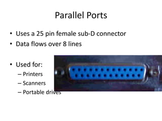
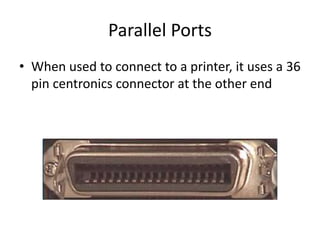
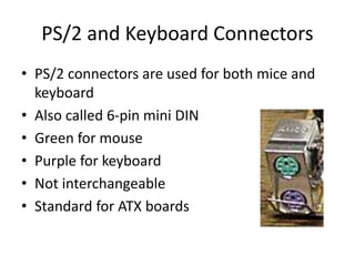
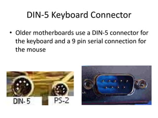
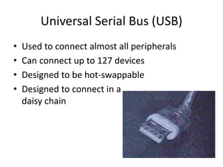
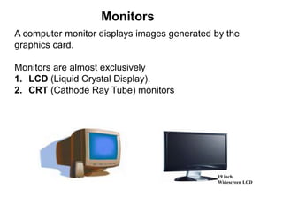
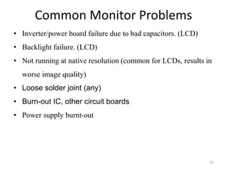
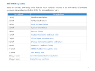
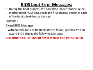
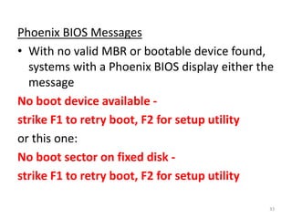
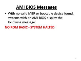
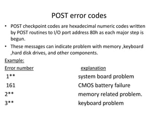
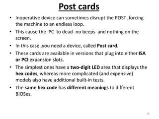
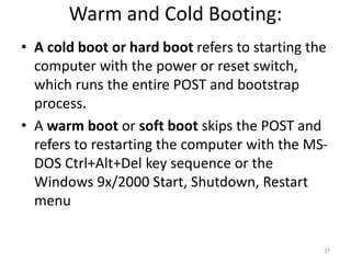
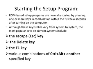
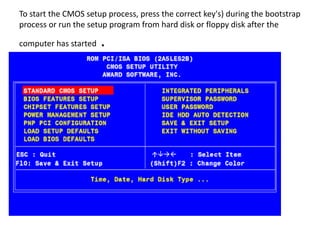
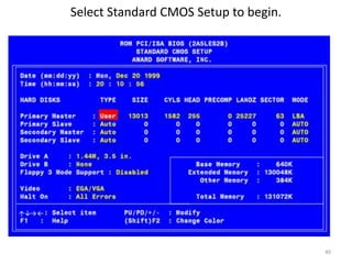
Computer Maintenance and Technical
Support
Chapter eight
I/O Connectors, BIOS
1
Chapter eight
I/O Connectors
•I/O Connectors
The Serial Port
The Parallel Port
I/O connectors
•The Monitor
Introduction to Monitor
Types of Displays
Health and Safety Concerns
Monitor Connections
Troubleshooting the Video System
2
• BIOS
Basic Input/ Output System
Error messages and solutions
Advanced BIOS Features
• Printer
Printer Types and Printer Technology
Printer Field Replaceable Units
Printer Maintenance Techniques
Serial Connectors
• Can use a 9 or 25 pin male sub-D connector
• Slowest ports
• Used for:
– Mice
– Keyboards
– Modems
Serial Ports
• Also called COM1, COM2, COM3, and COM4
• Can be referred to as a RS-232 port
• This is a standard that defines serial
communication
Parallel Ports
• Uses a 25 pin female sub-D connector
• Data flows over 8 lines
• Used for:
– Printers
– Scanners
– Portable drives
Parallel Ports
• When used to connect to a printer, it uses a 36
pin centronics connector at the other end
Parallel Ports
• Also called LPT1, LPT2, LPT3
• Bi-directional communication
– Called Enhanced Printer Port (EPP)
• Transmission mode can be set in the BIOS
• Maximum cable length is 15 feet
PS/2 and Keyboard Connectors
• PS/2 connectors are used for both mice and
keyboard
• Also called 6-pin mini DIN
• Green for mouse
• Purple for keyboard
• Not interchangeable
• Standard for ATX boards
DIN-5 Keyboard Connector
• Older motherboards use a DIN-5 connector for
the keyboard and a 9 pin serial connection for
the mouse
Universal Serial Bus (USB)
• Used to connect almost all peripherals
• Can connect up to 127 devices
• Designed to be hot-swappable
• Designed to connect in a
daisy chain
USB Standards
• USB 1.1 – 12 Mbps
• USB 2.0 – 480 Mbps
• USB 3.0 - 5gbps over ten times as fast as the 2.0
• A-Style connector is used on the computer or
hub
• B-Style connector is used on the device
• Must have Windows 98, 2000 or XP and
• Not supported in Windows 95 or NT 4.0
USB Cable Lengths
• Hi Powered devices – 5 meters max
– Also called hi-speed
• Low Powered devices – 3 meters max
– Also called low-speed
• Can be extended if you use a self-powered
hub
A computer monitor displays images generated by the
graphics card.
Monitors are almost exclusively
1. LCD (Liquid Crystal Display).
2. CRT (Cathode Ray Tube) monitors
Monitors
19 inch
Widescreen LCD
14
15
Common Monitor Problems
16
• Inverter/power board failure due to bad capacitors. (LCD)
• Backlight failure. (LCD)
• Not running at native resolution (common for LCDs, results in
worse image quality)
• Loose solder joint (any)
• Burn-out IC, other circuit boards
• Power supply burnt-out
Common Monitor Problems Solution
17
• Backlight failure can solve Replacing the CCFT (Cold-
Cathode Fluorescent Tubes.
• Find and replacing bad capacitors.
• Not running at native resolution problems can fix reinstalling
Drivers software.
• Soldering the board using hot gun.
• Check the brightness control button working properly
• Replacing burnt IC with the equivalent code.
• Check and maintain the power supply
BIOS
• BIOS stands for Basic Input/Output System ,which consists of low-
level software that controls the system hardware and act as an
interface between the operating system and the hardware.
• It is the lowest-level program that runs on your computer.
• The BIOS is what runs when you turn on your computer, and what
loads your operating.
• The BIOS also allows you to set or change many different
parameters that control how your computer will function. For
example, you tell the BIOS what sort of hard drives you have so it
knows how to access them.
• Most people know the term BIOS by another name—device drivers,
or just drivers
• In other words, the BIOS is drivers, meaning all of them. The BIOS is
essentially the link between hardware and software in a system.
• The BIOS itself is software running in memory that consists of all
the various drivers that interface the hardware to the operating
system.
18
BIOS in a PC comes from three possible sources
• Mother board
• Adapter card(such as that found on video card)
• Loaded into RAM from Disk
ROM chip also contained a power-on self test (POST)
program and a bootstrap loader.
• The bootstrap program was designed to initiate the
loading of an OS by checking for and loading the boot
sector from a floppy disk or, if one was not present, a
hard disk
• After the OS was loaded, it could call on the low-level
routines (device drivers) in the BIOS to interact with
the system hardware.
19
Tasks that the BIOS chip performs include:
• Configuration and control of standard devices:
• The power-on self test (POST)
• The location of an operating system, to which it turns
over control of the system by using the Bootstrap
loader
20
The BIOS and Standard Devices:
The BIOS is a complex piece of firmware ("software on a chip")
that provides support for the following devices and features
of your system:
• Selection and configuration of storage devices, such as hard
drives, floppy drives, and CD-ROM drives
• Configuration of main and cache memory:
• Configuration of built-in ports, such as IDE hard disk, floppy
disk, serial, parallel, PS/2 mouse, and USB
• Selection and configuration of special motherboard features,
such as memory error correction, antivirus protection, and
fast memory access
21
• Support for different CPU types, speeds, and special
features
• Support for advanced operating systems, including
networks, Windows 9x, and Windows 2000 (Plug and
Play)
• Power management
• Storing System Settings:
To enable the BIOS to perform these tasks, two other
components on the mother- board work with the
BIOS, these are :
22
• The CMOS chip, also known as the RTC/NVRAM
(Real-Time-Clock/Non-Volatile RAM),
• The battery
CMOS (Complementary Metal-Oxide semiconductor) chip
stores the settings that you make with the BIOS configuration
program.
It stores information such as system time,system settings for
your PC. It is modified and changed by entering the the
CMOS setup.
 The CMOS stores the settings that you make with the BIOS
configuration program and contains the system's Real-Time-
Clock circuit.
 Power from a battery attached to the motherboard is used
by the CMOS to keep its settings
23
Fig below shows typical socketed BIOS and battery
24
POST
• The POST (power-on self test) portion of the
BIOS allows the BIOS to find and report errors
in the computer's hardware.
• For the POST to work correctly, the system
must be configured correctly
25
The POST checks the following parts of the computer:
• The CPU and the POST ROM portion of the BIOS
• The system timer
• Video display card
• Memory
• The keyboard
• The disk drives
 The system will stop the boot process if it encounters a
serious or fatal error
26
During the POST process, the BIOS uses any one of
several methods to report problems:
•Beep codes
•Onscreen error messages
•POST error codes
Beep Codes:
•are used by most BIOS versions to indicate
either a fatal error or a very serious error.
•are used by most BIOS versions to indicate
either a fatal error or a very serious error.
27
• A fatal error would include a problem with the CPU, the POST
ROM, the system timer, or memory
• Beep codes vary by the BIOS maker.
• Some companies, such as IBM, Acer, and Compaq, create
their own BIOS chips and firmware
• most other major brands of computers and virtually all
"clones" use BIOS made by one of the "Big Three" BIOS
vendors:
 American Megatrends (AMI),
 Phoenix Technologies
 Award Software (now owned by Phoenix Technologies).
28
Below are IBM BIOS Beep codes that can occur. However, because of the
wide variety of models shipping with this BIOS, the beep codes may vary.
29
30
31
BIOS boot Error Messages:
• During the boot process, the bootstrap loader routine in the
motherboard ROM BIOS reads the first physical sector of each
of the bootable drives or devices.
Example :
Award BIOS Messages
With no valid MBR or bootable device found, systems with an
Award BIOS display the following Message:
DISK BOOT FAILURE, INSERT SYSTEM DISK AND PRESS ENTER
32
Phoenix BIOS Messages
• With no valid MBR or bootable device found,
systems with a Phoenix BIOS display either the
message
No boot device available -
strike F1 to retry boot, F2 for setup utility
or this one:
No boot sector on fixed disk -
strike F1 to retry boot, F2 for setup utility
33
AMI BIOS Messages
• With no valid MBR or bootable device found,
systems with an AMI BIOS display the
following message:
NO ROM BASIC - SYSTEM HALTED
34
POST error codes
• POST checkpoint codes are hexadecimal numeric codes written
by POST routines to I/O port address 80h as each major step is
begun.
• These messages can indicate problem with memory ,keyboard
,hard disk drives, and other components.
Example:
Error number explanation
1** system board problem
161 CMOS battery failure
2** memory related problem.
3** keyboard problem
Post cards
• Inoperative device can sometimes disrupt the POST ,forcing
the machine to an endless loop.
• This cause the PC to dead- no beeps and nothing on the
screen.
• In this case ,you need a device, called Post card.
• These cards are available in versions that plug into either ISA
or PCI expansion slots.
• The simplest ones have a two-digit LED area that displays the
hex codes, whereas more complicated (and expensive)
models also have additional built-in tests.
• The same hex code has different meanings to different
BIOSes.
36
Warm and Cold Booting:
• A cold boot or hard boot refers to starting the
computer with the power or reset switch,
which runs the entire POST and bootstrap
process.
• A warm boot or soft boot skips the POST and
refers to restarting the computer with the MS-
DOS Ctrl+Alt+Del key sequence or the
Windows 9x/2000 Start, Shutdown, Restart
menu
37
Starting the Setup Program:
• ROM-based setup programs are normally started by pressing
one or more keys in combination within the first few seconds
after turning on the computer.
• Although these keystrokes vary from system to system, the
most popular keys on current systems include:
the escape (Esc) key
 the Delete key
the F1 key
various combinations of Ctrl+Alt+ another
specified key
To start the CMOS setup process, press the correct key's) during the bootstrap
process or run the setup program from hard disk or floppy disk after the
computer has started .
Select Standard CMOS Setup to begin.
40
To clear an unknown BIOS password
• On the motherboard locate the BIOS clear /password
jumper or DIP switch and change its position . Once
cleared ,turn the computer off and return the
jumper or DIP switch to its original position.
• Remove the CMOS Battery for at least 10 minutes.
• If none of these works ,contact the computer
/motherboard manufacturer for steps on clearing the
computer password.
• Precaution: When inside the computer please be
sure of the potential of ESD.
41
42
Printer
• An external hardware device responsible for
taking computer data and generating a hard
copy of that data. Printers are one of the most
commonly used peripherals and they print
text and still images on the paper.
Thermal
Inkjet
Dot-Matrix Laser
43
Printers
Impact Printers Non-Impact Printers
Daisy
wheel
Dot-
Matrix
Inkjet Thermal Laser
Common printer problems
44
• paper jams
• Windows is sending print jobs to the wrong printer.
• your printer may run out of memory.
• Printer is too slow
• Toner does not stick to the page or smears
• Printer is displaying a 50.4 error message
Printer Problems Solution
45
• Periodically wipe the feeder tires clean and from time to time,
vacuum away dust build up inside the printer
• Load quality paper in the try.
• Select the working printer as a default.
• Expand/insert additional printer memory size.
• Reinstalling the driver.
46
a. The fuser assembly may be defective or it is at the end of life. The
solution is to replace the fuser . The fuser is considered a
consumable and can be replaced
b. You may have a defective toner cartridge. Simply replace the
cartridge and see if this fixes the problem, or
c. Toner may have spilled into the printer. Clean out the printer.
Toner does not stick to the page or smears
a. Periodically clean the printer
b. Replacing rollers/gears
c. Use the correct paper type
paper jams
47
a. If the printer is plugged into a UPS, or a power strip, unplug it
and plug the printer directly into the wall.
b. A laser printer should never be plugged into a UPS because of
the power surges required by the printer. These surges are
required by the printer to keep the fuser assembly warm.
Printer is displaying a 50.4 error message
a. The printer is low on toner, so Remove the toner cartridge,
and shake.
b. The print density is set too low, or change the setting
c. The printer may have the Economode turned on. So you
need Turn Economode off
Part of or all of the printed page is faded
48
As new operating systems are released/installed , new drivers
need to be loaded for your exiting printers in the computer .
Can’t find a driver for a particular operating system
a. correct it with the application by clicking on Printer
Properties and find the tray selection source.
b. check the printer. Make sure that the paper size on the
control panel matches what is actually in the paper tray.
Printer is not printing from the expected tray
End of Class
49
Thank You

Lecture_Chapter_8.ppt

  • 1.
    Computer Maintenance andTechnical Support Chapter eight I/O Connectors, BIOS 1
  • 2.
    Chapter eight I/O Connectors •I/OConnectors The Serial Port The Parallel Port I/O connectors •The Monitor Introduction to Monitor Types of Displays Health and Safety Concerns Monitor Connections Troubleshooting the Video System 2 • BIOS Basic Input/ Output System Error messages and solutions Advanced BIOS Features • Printer Printer Types and Printer Technology Printer Field Replaceable Units Printer Maintenance Techniques
  • 3.
    Serial Connectors • Canuse a 9 or 25 pin male sub-D connector • Slowest ports • Used for: – Mice – Keyboards – Modems
  • 4.
    Serial Ports • Alsocalled COM1, COM2, COM3, and COM4 • Can be referred to as a RS-232 port • This is a standard that defines serial communication
  • 5.
    Parallel Ports • Usesa 25 pin female sub-D connector • Data flows over 8 lines • Used for: – Printers – Scanners – Portable drives
  • 6.
    Parallel Ports • Whenused to connect to a printer, it uses a 36 pin centronics connector at the other end
  • 7.
    Parallel Ports • Alsocalled LPT1, LPT2, LPT3 • Bi-directional communication – Called Enhanced Printer Port (EPP) • Transmission mode can be set in the BIOS • Maximum cable length is 15 feet
  • 8.
    PS/2 and KeyboardConnectors • PS/2 connectors are used for both mice and keyboard • Also called 6-pin mini DIN • Green for mouse • Purple for keyboard • Not interchangeable • Standard for ATX boards
  • 9.
    DIN-5 Keyboard Connector •Older motherboards use a DIN-5 connector for the keyboard and a 9 pin serial connection for the mouse
  • 10.
    Universal Serial Bus(USB) • Used to connect almost all peripherals • Can connect up to 127 devices • Designed to be hot-swappable • Designed to connect in a daisy chain
  • 11.
    USB Standards • USB1.1 – 12 Mbps • USB 2.0 – 480 Mbps • USB 3.0 - 5gbps over ten times as fast as the 2.0 • A-Style connector is used on the computer or hub • B-Style connector is used on the device • Must have Windows 98, 2000 or XP and • Not supported in Windows 95 or NT 4.0
  • 12.
    USB Cable Lengths •Hi Powered devices – 5 meters max – Also called hi-speed • Low Powered devices – 3 meters max – Also called low-speed • Can be extended if you use a self-powered hub
  • 13.
    A computer monitordisplays images generated by the graphics card. Monitors are almost exclusively 1. LCD (Liquid Crystal Display). 2. CRT (Cathode Ray Tube) monitors Monitors 19 inch Widescreen LCD
  • 14.
  • 15.
  • 16.
    Common Monitor Problems 16 •Inverter/power board failure due to bad capacitors. (LCD) • Backlight failure. (LCD) • Not running at native resolution (common for LCDs, results in worse image quality) • Loose solder joint (any) • Burn-out IC, other circuit boards • Power supply burnt-out
  • 17.
    Common Monitor ProblemsSolution 17 • Backlight failure can solve Replacing the CCFT (Cold- Cathode Fluorescent Tubes. • Find and replacing bad capacitors. • Not running at native resolution problems can fix reinstalling Drivers software. • Soldering the board using hot gun. • Check the brightness control button working properly • Replacing burnt IC with the equivalent code. • Check and maintain the power supply
  • 18.
    BIOS • BIOS standsfor Basic Input/Output System ,which consists of low- level software that controls the system hardware and act as an interface between the operating system and the hardware. • It is the lowest-level program that runs on your computer. • The BIOS is what runs when you turn on your computer, and what loads your operating. • The BIOS also allows you to set or change many different parameters that control how your computer will function. For example, you tell the BIOS what sort of hard drives you have so it knows how to access them. • Most people know the term BIOS by another name—device drivers, or just drivers • In other words, the BIOS is drivers, meaning all of them. The BIOS is essentially the link between hardware and software in a system. • The BIOS itself is software running in memory that consists of all the various drivers that interface the hardware to the operating system. 18
  • 19.
    BIOS in aPC comes from three possible sources • Mother board • Adapter card(such as that found on video card) • Loaded into RAM from Disk ROM chip also contained a power-on self test (POST) program and a bootstrap loader. • The bootstrap program was designed to initiate the loading of an OS by checking for and loading the boot sector from a floppy disk or, if one was not present, a hard disk • After the OS was loaded, it could call on the low-level routines (device drivers) in the BIOS to interact with the system hardware. 19
  • 20.
    Tasks that theBIOS chip performs include: • Configuration and control of standard devices: • The power-on self test (POST) • The location of an operating system, to which it turns over control of the system by using the Bootstrap loader 20
  • 21.
    The BIOS andStandard Devices: The BIOS is a complex piece of firmware ("software on a chip") that provides support for the following devices and features of your system: • Selection and configuration of storage devices, such as hard drives, floppy drives, and CD-ROM drives • Configuration of main and cache memory: • Configuration of built-in ports, such as IDE hard disk, floppy disk, serial, parallel, PS/2 mouse, and USB • Selection and configuration of special motherboard features, such as memory error correction, antivirus protection, and fast memory access 21
  • 22.
    • Support fordifferent CPU types, speeds, and special features • Support for advanced operating systems, including networks, Windows 9x, and Windows 2000 (Plug and Play) • Power management • Storing System Settings: To enable the BIOS to perform these tasks, two other components on the mother- board work with the BIOS, these are : 22
  • 23.
    • The CMOSchip, also known as the RTC/NVRAM (Real-Time-Clock/Non-Volatile RAM), • The battery CMOS (Complementary Metal-Oxide semiconductor) chip stores the settings that you make with the BIOS configuration program. It stores information such as system time,system settings for your PC. It is modified and changed by entering the the CMOS setup.  The CMOS stores the settings that you make with the BIOS configuration program and contains the system's Real-Time- Clock circuit.  Power from a battery attached to the motherboard is used by the CMOS to keep its settings 23
  • 24.
    Fig below showstypical socketed BIOS and battery 24
  • 25.
    POST • The POST(power-on self test) portion of the BIOS allows the BIOS to find and report errors in the computer's hardware. • For the POST to work correctly, the system must be configured correctly 25
  • 26.
    The POST checksthe following parts of the computer: • The CPU and the POST ROM portion of the BIOS • The system timer • Video display card • Memory • The keyboard • The disk drives  The system will stop the boot process if it encounters a serious or fatal error 26
  • 27.
    During the POSTprocess, the BIOS uses any one of several methods to report problems: •Beep codes •Onscreen error messages •POST error codes Beep Codes: •are used by most BIOS versions to indicate either a fatal error or a very serious error. •are used by most BIOS versions to indicate either a fatal error or a very serious error. 27
  • 28.
    • A fatalerror would include a problem with the CPU, the POST ROM, the system timer, or memory • Beep codes vary by the BIOS maker. • Some companies, such as IBM, Acer, and Compaq, create their own BIOS chips and firmware • most other major brands of computers and virtually all "clones" use BIOS made by one of the "Big Three" BIOS vendors:  American Megatrends (AMI),  Phoenix Technologies  Award Software (now owned by Phoenix Technologies). 28
  • 29.
    Below are IBMBIOS Beep codes that can occur. However, because of the wide variety of models shipping with this BIOS, the beep codes may vary. 29
  • 30.
  • 31.
  • 32.
    BIOS boot ErrorMessages: • During the boot process, the bootstrap loader routine in the motherboard ROM BIOS reads the first physical sector of each of the bootable drives or devices. Example : Award BIOS Messages With no valid MBR or bootable device found, systems with an Award BIOS display the following Message: DISK BOOT FAILURE, INSERT SYSTEM DISK AND PRESS ENTER 32
  • 33.
    Phoenix BIOS Messages •With no valid MBR or bootable device found, systems with a Phoenix BIOS display either the message No boot device available - strike F1 to retry boot, F2 for setup utility or this one: No boot sector on fixed disk - strike F1 to retry boot, F2 for setup utility 33
  • 34.
    AMI BIOS Messages •With no valid MBR or bootable device found, systems with an AMI BIOS display the following message: NO ROM BASIC - SYSTEM HALTED 34
  • 35.
    POST error codes •POST checkpoint codes are hexadecimal numeric codes written by POST routines to I/O port address 80h as each major step is begun. • These messages can indicate problem with memory ,keyboard ,hard disk drives, and other components. Example: Error number explanation 1** system board problem 161 CMOS battery failure 2** memory related problem. 3** keyboard problem
  • 36.
    Post cards • Inoperativedevice can sometimes disrupt the POST ,forcing the machine to an endless loop. • This cause the PC to dead- no beeps and nothing on the screen. • In this case ,you need a device, called Post card. • These cards are available in versions that plug into either ISA or PCI expansion slots. • The simplest ones have a two-digit LED area that displays the hex codes, whereas more complicated (and expensive) models also have additional built-in tests. • The same hex code has different meanings to different BIOSes. 36
  • 37.
    Warm and ColdBooting: • A cold boot or hard boot refers to starting the computer with the power or reset switch, which runs the entire POST and bootstrap process. • A warm boot or soft boot skips the POST and refers to restarting the computer with the MS- DOS Ctrl+Alt+Del key sequence or the Windows 9x/2000 Start, Shutdown, Restart menu 37
  • 38.
    Starting the SetupProgram: • ROM-based setup programs are normally started by pressing one or more keys in combination within the first few seconds after turning on the computer. • Although these keystrokes vary from system to system, the most popular keys on current systems include: the escape (Esc) key  the Delete key the F1 key various combinations of Ctrl+Alt+ another specified key
  • 39.
    To start theCMOS setup process, press the correct key's) during the bootstrap process or run the setup program from hard disk or floppy disk after the computer has started .
  • 40.
    Select Standard CMOSSetup to begin. 40
  • 41.
    To clear anunknown BIOS password • On the motherboard locate the BIOS clear /password jumper or DIP switch and change its position . Once cleared ,turn the computer off and return the jumper or DIP switch to its original position. • Remove the CMOS Battery for at least 10 minutes. • If none of these works ,contact the computer /motherboard manufacturer for steps on clearing the computer password. • Precaution: When inside the computer please be sure of the potential of ESD. 41
  • 42.
    42 Printer • An externalhardware device responsible for taking computer data and generating a hard copy of that data. Printers are one of the most commonly used peripherals and they print text and still images on the paper. Thermal Inkjet Dot-Matrix Laser
  • 43.
    43 Printers Impact Printers Non-ImpactPrinters Daisy wheel Dot- Matrix Inkjet Thermal Laser
  • 44.
    Common printer problems 44 •paper jams • Windows is sending print jobs to the wrong printer. • your printer may run out of memory. • Printer is too slow • Toner does not stick to the page or smears • Printer is displaying a 50.4 error message
  • 45.
    Printer Problems Solution 45 •Periodically wipe the feeder tires clean and from time to time, vacuum away dust build up inside the printer • Load quality paper in the try. • Select the working printer as a default. • Expand/insert additional printer memory size. • Reinstalling the driver.
  • 46.
    46 a. The fuserassembly may be defective or it is at the end of life. The solution is to replace the fuser . The fuser is considered a consumable and can be replaced b. You may have a defective toner cartridge. Simply replace the cartridge and see if this fixes the problem, or c. Toner may have spilled into the printer. Clean out the printer. Toner does not stick to the page or smears a. Periodically clean the printer b. Replacing rollers/gears c. Use the correct paper type paper jams
  • 47.
    47 a. If theprinter is plugged into a UPS, or a power strip, unplug it and plug the printer directly into the wall. b. A laser printer should never be plugged into a UPS because of the power surges required by the printer. These surges are required by the printer to keep the fuser assembly warm. Printer is displaying a 50.4 error message a. The printer is low on toner, so Remove the toner cartridge, and shake. b. The print density is set too low, or change the setting c. The printer may have the Economode turned on. So you need Turn Economode off Part of or all of the printed page is faded
  • 48.
    48 As new operatingsystems are released/installed , new drivers need to be loaded for your exiting printers in the computer . Can’t find a driver for a particular operating system a. correct it with the application by clicking on Printer Properties and find the tray selection source. b. check the printer. Make sure that the paper size on the control panel matches what is actually in the paper tray. Printer is not printing from the expected tray
  • 49.