SlideShare a Scribd company logo
1 of 54
Download to read offline
SERVICE MANUAL                               BA-5 CHASSIS
    MODEL               COMMANDER     DEST   CHASSIS NO.


    KV-20FS12           RM-Y173       US     SCC-S40A-A
    KV-20FS12           RM-Y173       CND    SCC-S41A-A
    KV-20FV12           RM-Y168       US     SCC-S40B-A
    KV-20FV12           RM-Y168       CND    SCC-S41B-A
    KV-21FE12           RM-Y173       E      SCC-S38A-A
    KV-21FE12A          RM-Y173       E      SCC-S38F-A
    KV-21FE12C          RM-Y173       E      SCC-S38B-A
    KV-21FM12           RM-Y172       MX     SCC-S39A-A
    KV-21FV12           RM-Y168       E      SCC-S38C-A
    KV-21FV12C          RM-Y168       E      SCC-S38D-A


            KV-21FV12                               RM-Y168


                                    TRINITRON® COLOR TV
KV-20FS12/20FV12/21FE12/A/C/21FM12/21FV12/C
                                                                                                      SPECIFICATIONS

                                                     KV-21FE12
                                                    KV-21FE12A
                                                    KV- 21FE12C                 KV-21FM12                       KV-20FS12                     KV-20FV12                  KV-21FV12                   KV-21FV12C
      Power requirements                       120-220V, 50/60 Hz            120-220V, 50/60 Hz                 120V,60Hz                     120V,60Hz               120-220V, 50/60 Hz          120-220V, 50/60 Hz
      Number of inputs/outputs
                       Video 1)                            2                           2                             2                              2                          2                           2
                    S Video 2)                             1                           1                             1                              1                          1                           1
                       Audio 3)                            2                           2                             2                              2                          2                           2
                  Audio Out 4)                             --                          --                            --                             1                          1                           1
      Speaker output(W)                                  5W x 2                      3W x 2                        3W x 2                         5W x 2                     10W x 2                     10W x 2
      Power Consumption(W)
                   In use(Max)                           115W                         115W                          115W                          150W                        155W                        150W
                     In standby                           1W                           1W                            1W                            1W                          1W                          1W
      Dimensions(W/H/D)
                           (mm)                 512 x 475 x 493mm             512 x 475 x 493mm             512 x 475 x 493mm              562 x 466 x 503mm           562 x 466 x 503mm           562 x 466 x 503mm
                              (in)             20 1/8 x 18 11/16 x 19 7/16   20 1/8 x 18 11/16 x 19 7/16   20 1/8 x 18 11/16 x 19 7/16     22 1/4 x 18 3/8 x 19 7/8    22 1/4 x 18 3/8 x 19 7/8    22 1/4 x 18 3/8 x 19 7/8
—2—


      Mass
                            (kg)                         24.5kg                      24.5kg                        24.5kg                        27 kg                       27 kg                       27 kg
                            (lbs)                         54 lbs                      54 lbs                        54 lbs                    59 lbs. 8 oz.               59 lbs. 8 oz.               59 lbs. 8 oz.

      1)   Vp-p 75 ohms unbalanced, sync negative
      2)   Y: 1 Vp-p 75 ohms unbalanced, sync negative                       Television system                                      Supplied accessories
           C: 0.286 Vp-p (Burst signal), 75 ohms
                                                                                 American TV standard/NTSC                               Remote Commander RM-Y168 (KV-20FV12/21FV12/21FV12C ONLY)
      3)   500mVrms (100% modulation), impedance: 47kilohms
                                                                                 PAL M, N (KV-21FE12A ONLY)                              Remote Commander RM-Y172 (KV-21FM12 ONLY)
      4)   More than 408 mVrms at the maximum volume setting (variable).
           More than 408 mVrms (fix).                                                                                                    Remote Commander RM-Y173 (KV-20FS12/21FE12/21FE12A/21FE12C ONLY)
                                                                             Channel coverage                                            Size AA (R6) batteries (2)
                                                                                 VHF:2-13/UHF:14-69/CATV:1-125
                                                                                                                                    Optional accessories
                                                                             Visible screen size                                         Connecting cables: VMC-810S/820S, VMC-720M,
                                                                                                                                         YC-15V/30V, RK74A
                                                                                 20” picture measured diagonally
                                                                                                                                         U/V mixer EAC-66
                                                                             Actual screen size
                                                                                 21” picture measured diagonally

                                                                             Antenna
                                                                                 75 ohm external antenna terminal for VHF/UHF

                                                                                                                                                 Design and specifications are subject to change without notice.
KV-20FS12/20FV12/21FE12/A/C/21FM12/21FV12/C

                                                                           TABLE OF CONTENTS

Section                                             Title                                                                                                                                         Page

          Warnings and Cautions ............................................................................................................................................................... 4
          Self-Diagnostic Function ............................................................................................................................................................. 4
          Safety Check-Out Instructions .................................................................................................................................................... 7

  1.      GENERAL ........................................................................................................................................................... 8

  2.      DISASSEMBLY
          2-1.       Rear Cover Removal ..................................................................................................................................................... 13
          2-2.       Chassis Assembly Removal ......................................................................................................................................... 13
          2-3.       Service Position ............................................................................................................................................................ 13
          2-4.       Picture Tube Removal ................................................................................................................................................... 14

  3.      SET-UP ADJUSTMENTS
          3-1.       Beam Landing ............................................................................................................................................................... 15
          3-2.       Convergence ................................................................................................................................................................. 16
          3-3.       Focus ............................................................................................................................................................................. 17
          3-4.       Screen (G2) ................................................................................................................................................................... 17
          3-5.       Method of Setting the Service Adjustment Mode .............................................................................. ........................... 18
          3-6.       White Balance Adjustments .......................................................................................................................................... 18

  4.      SAFETY RELATED ADJUSTMENTS
          4-1.          R562 Confirmation Method (HV Hold-Down Confirmation and Readjustments) .................................................... 19
          4-2.       B+ Voltage Confirmation and Adjustment ..................................................................................................................... 19

  5.      CIRCUIT ADJUSTMENTS
          5-1.       Setting the Service Adjustment Mode .......................................................................................................................... 21
          5-2.       Memory Write Confirmation Method ............................................................................................................................. 21
          5-3.       Adjustment Buttons and Indicators ............................................................................................................................... 21
          5-4.       MB Board Adjustments ................................................................................................................................................. 23

  6.      DIAGRAMS
          6-1.       Block Diagram ............................................................................................................................................................... 27
          6-2.       Circuit Board Location .................................................................................................................................................. 30
          6-3.       Printed Wiring Boards and Schematic Diagrams ......................................................................................................... 30
                     • A Board .................................................................................................................................................................... 31
                     • K Board .................................................................................................................................................................... 38
                     • MB Board ................................................................................................................................................................. 39
                     • CB Board .................................................................................................................................................................. 47
                     • VB Board .................................................................................................................................................................. 49
                     • HZ Board .................................................................................................................................................................. 50
          6-4.       Semiconductors ............................................................................................................................................................ 51

  7.      EXPLODED VIEW
          7-1.       Chassis (KV-21FE12/C ONLY) .................................................................................................................................... 52
          7-2.       Chassis (KV-21FE12A MODEL ONLY) ......................................................................................................................... 53
          7-3.       Chassis (KV-20FV12/21FV12/C ONLY) ....................................................................................................................... 54
          7-4.       Chassis (KV-20FS12/21FM12 ONLY) .......................................................................................................................... 55

  8.      ELECTRICAL PARTS LIST ................................................................................................................................................. 56


                                                                                                 —3—
KV-20FS12/20FV12/21FE12/A/C/21FM12/21FV12/C
                                                           WARNINGS AND CAUTIONS

                               CAUTION                                                                                 ATTENTION!!
   SHORT CIRCUIT THE ANODE OF THE PICTURE TUBE                                 APRES AVOIR DECONNECTE LE CAP DE L'ANODE, COURT-CIRCUITER
   AND THE ANODE CAP TO THE METAL CHASSIS, CRT                                 L'ANODE DU TUBE CATHODIQUE ET CELUI DE L'ANODE DU CAP AU
   SHIELD, OR CARBON PAINTED ON THE CRT, AFTER                                 CHASSIS METALLIQUE DE L'APPAREIL, OU AU COUCHE DE CARBONE
   REMOVING THE ANODE.                                                         PEINTE SUR LE TUBE CATHODIQUE OU AU BLINDAGE DU TUBE
                                                                               CATHODIQUE.
                             WARNING!!
                                                                                                                       ATTENTION!!
   AN ISOLATION TRANSFORMER SHOULD BE USED
   DURING ANY SERVICE TO AVOID POSSIBLE SHOCK                                  AFIN D'EVITER TOUT RESQUE D'ELECTROCUTION PROVENANT D'UN
   HAZARD, BECAUSE OF LIVE CHASSIS. THE CHASSIS                                CHÁSSIS SOUS TENSION, UN TRANSFORMATEUR D'ISOLEMENT DOIT ETRE
   OF THIS RECEIVER IS DIRECTLY CONNECTED TO THE                               UTILISÉ LORS DE TOUT DÉPANNAGE. LE CHÁSSIS DE CE RÉCEPTEUR EST
   AC POWER LINE.                                                              DIRECTEMENT RACCORDÉ À L'ALIMENTATION SECTEUR.

    SAFETY-RELATED COMPONENT WARNING!!                                           ATTENTION AUX COMPOSANTS RELATIFS A LA SECURITE!!

   COMPONENTS IDENTIFIED BY SHADING AND MARK                                   LES COMPOSANTS IDENTIFIES PAR UNE TRAME ET PAR UNE MARQUE
      ON THE SCHEMATIC DIAGRAMS, EXPLODED VIEWS,                                  SUR LES SCHEMAS DE PRINCIPE, LES VUES EXPLOSEES ET LES
   AND IN THE PARTS LIST ARE CRITICAL FOR SAFE                                 LISTES DE PIECES SONT D'UNEIMPORTANCE CRITIQUE POUR LA
   OPERATION. REPLACE THESE COMPONENTS WITH                                    SECURITE DU FONCTIONNEMENT. NE LES REMPLACER QUE PAR DES
   SONY PARTS WHOSE PART NUMBERS APPEAR AS                                     COMPOSANTS SONY DONT LE NUMERO DE PIECE EST INDIQUE DANS
   SHOWN IN THIS MANUAL OR IN SUPPLEMENTS                                      LE PRESENT MANUEL OU DANS DES SUPPLEMENTS PUBLIES PAR SONY.
   PUBLISHED BY SONY. CIRCUIT ADJUSTMENTS THAT                                 LES REGLAGES DE CIRCUIT DONT L'IMPORTANCE EST CRITIQUE POUR
   ARE CRITICAL FOR SAFE OPERATION ARE IDENTIFIED                              LA SECURITE DU FONCTIONNEMENT SONT IDENTIFIES DANS LE
   IN THIS MANUAL. FOLLOW THESE PROCEDURES                                     PRESENT MANUEL. SUIVRE CES PROCEDURES LORS DE CHAQUE
   WHENEVER CRITICAL COMPONENTS ARE REPLACED                                   REMPLACEMENT DE COMPOSANTS CRITIQUES, OU LORSQU'UN
   OR IMPROPER OPERATION IS SUSPECTED.                                         MAUVAIS FONTIONNEMENT SUSPECTE.


                                                         SELF-DIAGNOSTIC FUNCTION
   The units in this manual contain a self-diagnostic function. If an error occurs, the STANDBY/TIMER LED will automatically begin to flash.
   The number of times the LED flashes translates to a probable source of the problem. A definition of the STANDBY/TIMER LED flash
   indicators is listed in the instruction manual for the user’s knowledge and reference. If an error symptom cannot be reproduced, the Remote
   Commander can be used to review the failure occurrence data stored in memory to reveal past problems and how often these problems occur.


   Diagnostic Test Indicators
   When an error occurs, the STANDBY/TIMER LED will flash a set number of times to indicate the possible cause of the problem. If there is
   more than one error, the LED will identify the first of the problem areas.
   Results for all of the following diagnostic items are displayed on screen. No error has occurred if the screen displays a “0”.


                                     No. of Times
         Diagnostic Item                          Self-Diagnostic Display/                  Probable Cause
                                   STANDBY/TIMER                                                                                          Detected Symptoms
           Description                               Diagnostic Result                         Location
                                     LED Flashes

    Power does not turn on           Does not light                          • Power cord is not plugged in.               • Power does not come on.
                                                                             • Fuse is burned out. (F601) (A Board)        • No power is supplied to the TV.
                                                                                                                           • AC power supply is faulty.

    +B overcurrent (OCP)*               2 times            2:0 or 2:1        • H.OUT (Q502) is shorted. (A Board)          • Power does not come on.
                                                                             • IC702 is shorted. (CB Board)                • Load on power line is shorted.

    Vertical deflection stopped*        4 times            4:0 or 4:1        • +12V is not supplied. (A Board)             • Has entered standby state after horizontal raster.
                                                                             • IC502 is faulty. (A Board)                  • Vertical deflection pulse is stopped.
                                                                                                                           • Power line is shorted or power supply is stopped.

    White balance failure               5 times            5:0 or 5:1        • Video OUT (IC502) is faulty. (A Board)      • No raster is generated.
    (not balanced)                                                           • IC1301 is faulty. (MB Board)                • CRT cathode current detection reference
                                                                             • Screen (G2) is improperly adjusted.**         pulse output is small.


     * If a +B overcurrent is detected, stoppage of the vertical deflection is detected simultaneously.
       The symptom that is diagnosed first by the microcontroller is displayed on the screen.
   ** Refer to Screen (G2) Adjustments in Section 3-4 of this manual.


                                                                              —4—
KV-20FS12/20FV12/21FE12/A/C/21FM12/21FV12/C


Display of Standby/Timer LED Flash Count

                    2 times
                    4 times
                    5 times


    LED ON 0.3 sec.
                                                                                                       STANDBY/TIMER LED
    LED OFF 0.3 sec.                       LED OFF
                                             3 sec.


           Diagnostic Item                    Flash Count*
           +B overcurrent                       2 times
           Vertical deflection stopped          4 times
           White balance failure                5 times
           *One flash count is not used for self-diagnostic.


Stopping the Standby/Timer LED Flash
Turn off the power switch on the TV main unit or unplug the power cord from the outlet to stop the STANDBY/TIMER LAMP from flashing.


Self-Diagnostic Screen Display
For errors with symptoms such as “power sometimes shuts off” or “screen sometimes goes out” that cannot be confirmed, it is possible
to bring up past occurrences of failure on the screen for confirmation.


To Bring Up Screen Test
In standby mode, press buttons on the Remote Commander sequentially, in rapid succession, as shown below:

 Display          Channel 5          Sound volume              Power ON


                                                       Note that this differs from entering the service mode (sound volume + ).
Self-Diagnostic Screen Display


   SELF DIAGNOSTIC
   2:             0                          Numeral “0” means that no fault was detected.
   3:     N/A     0
   4:             0
   5:             1                          Numeral “1” means a fault was detected one time only.
   101:   N/A     0


                                                                —5—
KV-20FS12/20FV12/21FE12/A/C/21FM12/21FV12/C


   Handling of Self-Diagnostic Screen Display
   Since the diagnostic results displayed on the screen are not automatically cleared, always check the self-diagnostic screen during repairs.
   When you have completed the repairs, clear the result display to “0”.
   Unless the result display is cleared to “0”, the self-diagnostic function will not be able to detect subsequent faults after completion of the
   repairs.

   Clearing the Result Display
   To clear the result display to “0”, press buttons on the Remote Commander sequentially when the diagnostic screen is displayed,
   as shown below:

        Channel 8            ENTER

   Quitting the Self-Diagnostic Screen
   To quit the entire self-diagnostic screen, turn off the power switch on the Remote Commander or the main unit.


   Self-Diagnostic Circuit


                               MB BOARD               A BOARD                           MB BOARD                            MB BOARD
                                IC1301                  IC507                             IC1001                              IC1003
                           Y/CHROMA JUNGLE             V. OUT                            SYSTEM                              MEMORY


              FROM
                           21 IK IN                                                         IO-BDAT 36                  5   B-DAT
               CRT
                                                           REF   3                 17 I-PROT

            A BOARD
             FROM
                          18 HP/PROTECT
              IC502
              PIN 7                                                                             O-LED 18
                                      SDA 35                                       37 IO-SDAT                        DISPLAY


   +B overcurrent (OCP)                    Occurs when an overcurrent on the +B (135V) line is detected by pin 18 of IC1301 (MB Board).
                                           If the voltage of pin 18 of IC1301 (MB Board) is less than 1V when V.SYNC is more than seven
                                           verticals in a period, the unit will automatically turn off.

   Vertical deflection stopped             Occurs when an absence of the vertical deflection pulse is detected by pin 17 of IC1001 (MB
                                           Board). Power supply will shut down when waveform interval exceeds 2 seconds.

   White balance failure                   If the RGB levels* do not balance within 2 seconds after the power is turned on, this error will be
                                           detected by IC1301 (MB Board). TV will stay on, but there will be no picture.

                                           *(Refers to the RGB levels of the AKB detection Ref pulse that detects 1K).


                                                                     —6—
KV-20FS12/20FV12/21FE12/A/C/21FM12/21FV12/C
                                               SAFETY CHECK-OUT

After correcting the original service problem, perform the      Leakage Test
following safety checks before releasing the set to the         The AC leakage from any exposed metal part to earth
customer:                                                       ground and from all exposed metal parts to any exposed
                                                                metal part having a return to chassis, must not exceed
1. Check the area of your repair for unsoldered or poorly       0.5 mA (500 microamperes). Leakage current can be
   soldered connections. Check the entire board surface         measured by any one of three methods.
   for solder splashes and bridges.
                                                                1. A commercial leakage tester, such as the Simpson
2. Check the interboard wiring to ensure that no wires             229 or RCA WT-540A. Follow the manufacturers'
   are “pinched” or touching high-wattage resistors.               instructions to use these instructions.
3. Check that all control knobs, shields, covers, ground        2. A battery-operated AC milliammeter. The Data
   straps, and mounting hardware have been replaced.               Precision 245 digital multimeter is suitable for this job.
   Be absolutely certain that you have replaced all the
                                                                3. Measuring the voltage drop across a resistor by
   insulators.
                                                                   means of a VOM or battery-operated AC voltmeter.
4. Look for unauthorized replacement parts, particularly           The “limit” indication is 0.75 V, so analog meters must
   transistors, that were installed during a previous repair.      have an accurate low voltage scale. The Simpson’s
   Point them out to the customer and recommend their              250 and Sanwa SH-63TRD are examples of passive
   replacement.                                                    VOMs that are suitable. Nearly all battery-operated
5. Look for parts which, though functioning, show                  digital multimeters that have a 2 VAC range are
   obvious signs of deterioration. Point them out to the           suitable (see Figure A).
   customer and recommend their replacement.
6. Check the line cords for cracks and abrasion.                How to Find a Good Earth Ground
   Recommend the replacement of any such line cord              A cold-water pipe is a guaranteed earth ground; the cover-
   to the customer.                                             plate retaining screw on most AC outlet boxes is also at
7. Check the B+ and HV to see if they are specified             earth ground. If the retaining screw is to be used as your
   values. Make sure your instruments are accurate;             earth ground, verify that it is at ground by measuring the
   be suspicious of your HV meter if sets always have           resistance between it and a cold-water pipe with an
   low HV.                                                      ohmmeter. The reading should be zero ohms. If a cold-water
8. Check the antenna terminals, metal trim, “metallized”        pipe is not accessible, connect a 60- to 100-watt trouble-
   knobs, screws, and all other exposed metal parts for         light (not a neon lamp) between the hot side of the
   AC leakage. Check leakage as described below.                receptacle and the retaining screw. Try both slots, if
                                                                necessary, to locate the hot side on the line; the lamp should
                                                                light at normal brilliance if the screw is at ground potential
                                                                (see Figure B).


                                                                  Trouble Light
                                                                                              Ohmmeter
                                                                              AC Outlet Box


                                                                                                            Cold-water Pipe


   Figure A. Using an AC voltmeter to check AC leakage.                     Figure B. Checking for earth ground.


                                                           —7—
KV-20FS12/20FV12/21FE12/A/C/21FM12/21FV12/C
                                                                                            SECTION 1   GENERAL

      The instructions mentioned here are partial abstracts from the Operating Instruction Manual.         Operating Instructions
              The page numbers shown reflect those of the Operating Instruction Manual.


                                                                                                           Connecting Additional Equipment
                  Connecting Your TV                                                                       TV and VCR
                                                                                                                                                                       Rear of TV
                  Read this section before setting up your TV for the first time. This section
                  covers basic connections in addition to any optional equipment you may
                  be connecting.
                                                                                                                                     2
                  Basic Connections
                                                                                                               Coaxial         VCR
                  TV with indoor or outdoor antenna, or CATV cable                                             Cable
                  Depending on the cable available in your home, choose one of the                         1
                                                                                                               From
                  connections below:                                                                           cable/
                                                                                                               antenna


                                                                                                                                                3 (Optional connection)
—8—


                                                                                                           1    Connect the coaxial cable from your TV antenna or cable service to
                                                                                                                the IN jack on your VCR.
                                                                                                           2    Connect a coaxial cable (not supplied) from the OUT jack on your
                                                                                                                VCR to the VHF/UHF jack on the TV.

                                                                                                                 To watch video programs from your VCR, tune your TV to channel 3 or 4 (as
                                                                                                                  set on the rear of your VCR).

                                                                                                           (Optional connection)
                                                                                                           3    If your VCR is equipped with video outputs, you can get better
                                                                                                                picture quality by connecting A/V cables (not supplied) from
                                                                                                                AUDIO and VIDEO OUT on your VCR to AUDIO/VIDEO IN on
                                                                                                                your TV.

                                                                                                                 You can use the        button to switch between the VHF/UHF and VIDEO
                                                                                                                  inputs.


                      If you are connecting to an indoor or outdoor antenna, you may need to
                       adjust the orientation of the antenna for best reception.

                                                                                                3          4
Connecting Your TV         Operating Instructions


      TV and Cable Box                                                                         TV, VCR, and Cable box
                                           Cable Box
                                                                                                                                                                 Rear of TV
                   Coaxial
                   Cable
               1
                   From
                   cable
                                                                                                                     3


                                                                                                                                   VCR

                                                 Coaxial
                                           2     Cable

                                                       Rear of TV                                                    2

                                                                                                             Cable box
                                                                                                   Coaxial
                                                                                                   Cable                               4 (Optional connection)
                                                                                               1
                                                                                                   From
                                                                                                   cable
—9—


                                                                                               1    Connect the coaxial cable from your cable service to the IN jack on
                                                                                                    your cable box.
      1    Connect the coaxial cable from your cable service to the IN jack on                 2    Connect a coaxial cable (not supplied) from the OUT jack on your
           your cable box.                                                                          cable box to the IN jack on your VCR.
      2    Connect a coaxial cable (not supplied) from the OUT jack on your                    3    Connect a coaxial cable (not supplied) from the OUT jack on your


                                                                                                                                                                                     KV-20FS12/20FV12/21FE12/A/C/21FM12/21FV12/C
           cable box to the VHF/UHF jack on the TV.                                                 VCR to the VHF/UHF jack on the TV.

           To view channels from your cable box, tune your TV to channel 3 or 4 (as set             If you will be controlling all channel selection through your cable box, you
            on the rear panel of your cable box) and use the cable box’s remote control to            should consider using the Channel Fix feature, (see page 19).
            change channels.

                                                                                               (Optional connection)
           If you will be controlling all channel selection through your cable box, you
            should consider using the Channel Fix feature, (see page 19).                      4    If your VCR is equipped with video outputs, you can get better
                                                                                                    picture quality by connecting A/V cables (not supplied) from
                                                                                                    AUDIO and VIDEO OUT on your VCR to AUDIO/VIDEO IN on
                                                                                                    your TV.

                                                                                                     You can use the         button to switch between the VHF/UHF and VIDEO
                                                                                                      inputs.


                                                                                           5   6
KV-20FS12/20FV12/21FE12/A/C/21FM12/21FV12/C
                                                                            Connecting Your TV      Operating Instructions


         TV and Satellite Receiver                                                                  TV, Satellite Receiver, and VCR
                                                                            Rear of TV              Satellite
                                                                                                    antenna
                                                            2    From                               cable                                                                                                    Rear of TV
                                                                 cable/
                                                                 antenna                            1                  4                                                                  From
                                                                                                                                                                                          cable/
                                                                                                                                                                                          antenna
                                                                                                                                                       VCR
                                                                                                    SATELLITE IN
                           Satellite receiver                                                                                               VHF/UHF
                                                                                                                    AUDIO R AUDIO L VIDEO        IN               AUDIO R AUDIO L VIDEO                  2
                1         SATELLITE IN
                                                                 VHF/UHF
                                                                                                        LINE OUT
                                                                                                                                                 OUT   LINE IN                            VHF/UHF
                                                                                                                                                                                               IN
                                         AUDIO R AUDIO L VIDEO        IN
             Satellite                                                                              Satellite receiver                                 LINE OUT
                                                                                                                                                                                               OUT
                                                                      OUT
             antenna       LINE OUT
             cable                                                                                                                                                                                   3

                                                                                                                                                                  5

                                              3

                                                                                                    1        Connect the cable from your satellite antenna to SATELLITE IN on
                                                                                                             your satellite receiver.
— 10 —


                                                                                                    2        Connect the coaxial cable from your cable service or antenna to the
         1    Connect the cable from your satellite antenna to SATELLITE IN on                               IN jack on your VCR.
              your satellite receiver.
                                                                                                    3        Using a coaxial cable, connect the OUT jack on your VCR to the
         2    Connect the coaxial cable from your cable service or antenna to the                            VHF/UHF jack on your TV.
              VHF/UHF jack on your TV.
                                                                                                    4        Using A/V cables, connect AUDIO and VIDEO OUT on your
         3    Using A/V cables, connect AUDIO and VIDEO OUT on your                                          satellite receiver to AUDIO and VIDEO IN on your VCR.
              satellite receiver to AUDIO and VIDEO IN on your TV.
                                                                                                    5        Using A/V cables, connect AUDIO and VIDEO OUT on your VCR to
                                                                                                             AUDIO and VIDEO IN on your TV.
              You can use the                 button to switch between the VHF/UHF and VIDEO
               inputs.
                                                                                                                  To view from the satellite receiver or VCR, select the video input to which
                                                                                                                   your VCR is connected by pressing           on the remote control.


                                                                                                7   8
Operating Instructions
         Using the Remote Control and
         Basic Functions                                                                                                              MENU    Displays the on-screen menu.
                                                                                                                                              Press again to exit the menu at
         This section shows you how to use the more advanced buttons on the                                                                   any time.
         remote control and how to use the on-screen menus.
                                                                                                                                      RESET   Press to return to factory settings
                                                                                                                                              while in an on-screen menu.
         Using the Remote Control
                                                       Button     Description
                                                       POWER      Press when you want to turn the
                                                                  TV on and off.
                                                       MUTING     Instantly turns off the sound.
                                                                  Press again or press     to restore
                MUTING
                            SLEEP
                                       POWER
                                                                  sound.
                MTS/SAP     DISPLAY   TV/VIDEO
                                                       TV/VIDEO   Cycles through available video
                                                                  inputs.
                  1           2            3                      Moves the cursor in the on-
                                                                  screen menus. Press the arrow
                  4           5            6
                                                                  buttons to move the cursor. Press
— 11 —


                  7           8            9                      the center button to select or
                 JUMP                   ENTER                     access an option.
                              0
                      VOL             CH               SLEEP      Turns the TV off automatically in
                                                                  approximately 15, 30, 45, 60, or
                                                                  90 minutes. Cancel by pressing
                                                                  until SLEEP OFF appears.
              RESET                             MENU   MTS/SAP    Cycles through the Multi-


                                                                                                                                                                                    KV-20FS12/20FV12/21FE12/A/C/21FM12/21FV12/C
                                                                  channel TV Sound (MTS)
                                                                  options: Stereo, Mono, and
                                                                  Auto-SAP (Second Audio
                                                                  Programming) (KV-21FE12
                                      RM-Y173
                                                                  models only).
                                                       DISPLAY    Press to display the current time,
                             TV                                   (if set) and channel number.
                                                       JUMP       Alternates between the last two
                                                                  channels selected with the
                                                                   0   9 buttons.


              The remote control illustrated (RM-Y173) is for KV-21FE12 models. For
               KV-21FM12 and KV-14FM12 models, your remote control does not have the
               MTS/SAP button.

                                                                                              (Continued)

                                                                                                        11   12
KV-20FS12/20FV12/21FE12/A/C/21FM12/21FV12/C
         Operating Instructions                                                                                                                 Other Information


         Other Information                                                              Cannot receive
                                                                                        higher number
                                                                                                         t   Make sure Cable is set to OFF in the Options menu
                                                                                                             under Setup (page 23).
                                                                                        channels (UHF)   t   Perform Auto Program to add channels that are not
                                                                                        when using an
         Troubleshooting                                                                antenna
                                                                                                             presently in the memory (page 23).

         If you are having a problem with your TV, try the suggestions below. If        Cable stations   t   Make sure Cable is set to ON in the Options menu
         the problem persists, contact your nearest Sony dealer.                        don’t seem to        under Setup (page 23).
                                                                                        work             t   Perform Auto Program to add channels that are not
         No picture, no    t   Make sure the power cord is plugged in.                                       presently in the memory (page 23).
         sound             t   If a red light is flashing on the front of your TV for   Remote control   t   Batteries could be weak. Replace them (page 2).
                               more than a few minutes, disconnect and reconnect        does not         t   Move the TV 3-4 feet or more away from fluorescent
                               the power cord to restore the TV. If the problem         operate              lights.
                               continues, call your local service center.
                           t   Check the TV/VIDEO settings: when watching TV, set       The TV needs     t   Clean the TV with a soft dry cloth. Never use strong
                               to TV; when watching video equipment, set to VIDEO       to be cleaned        solvents such as thinner or benzine, which might
                               (page 11).                                                                    damage the finish of the cabinet.
                           t   Make sure the batteries have been inserted correctly
                               into the remote control.
                           t   Try another channel, it could be station trouble.
— 12 —


         Poor or no        t   Adjust Picture in the Video menu (page 17).
         picture, good     t   Adjust Brightness in the Video menu (page 17).
         sound             t   Check the antenna and/or cable connections (page 3).
                                    MUTING

         Good picture,     t   Press     so that MUTING disappears from the
         no sound              screen (page 11).
                           t   Check your Audio settings. Your TV may be set to
                               Auto-SAP (page 18).
         No color          t   Adjust Color in the Video menu (page 17).
         No signal         t   Check the Cable setting in the Options menu under
                               Setup (page 23).
                           t   Check the antenna and/or cable connections (page 3).
                           t   Make sure the channel selected is currently
                               broadcasting.
         Dotted lines or   t   Adjust the antenna.
         stripes           t   Move the TV away from other electronic equipment.
                               Some electronic equipment can create electrical noise,
                               which can interfere with TV reception.
         Double images     t   Check your outdoor antenna or call your cable service.
         or ghosts


         24                                                                                                                                                         25
KV-20FS12/20FV12/21FE12/A/C/21FM12/21FV12/C


                                            SECTION 2
                                          DISASSEMBLY


2-1. REAR COVER REMOVAL


                                                                                    Screw +BVTP 4x16
   Screw +BVTP 4x16


                                                                                    Rear Cover


                                                                                   Screw +BVTP 4x16
     Screw +BVTP 4x16
                                                                        2 Screws +BVTP 4x12


2-2. CHASSIS ASSEMBLY REMOVAL                          2-3. SERVICE POSITION


                                                             CB Board


                                                       VB Board
                                         CB Board


                                                       MB Board


                                          VB Board


 MB Board
                                                    Extension Cable                           A Board
    Claw                             A Board
                                                    for Service
                                                    p/n S-1294-965-A      K Board
             K Board                                                      (KV-20FV12/21FV12/C ONLY)
             (KV-20FV12/21FV12/C ONLY)

                                               — 13 —
KV-20FS12/20FV12/21FE12/A/C/21FM12/21FV12/C


   2-4. PICTURE TUBE REMOVAL

                  WARNING:
               BEFORE REMOVING                             10                                                                             1
                THE ANODE CAP

        High voltage remains in the CRT
        even after the power is disconnected.                                                                                             2
        To avoid electric shock, discharge
        CRT before attempting to remove the
        anode cap. Short between anode and                  9                                                                             3
        CRT coated earth ground strap.
                                                            8

                                                            7

                                                            6
         Coated
          Earth                                             5
         Ground
          Strap


                                                                                       4


   1.     Discharge the anode of the CRT and remove the anode cap.               6.   Loosen the deflection yoke fixing screw and remove.
   2.     Unplug all interconnecting leads from the deflection yoke, neck        7.   Place the set with the CRT face down on a cushion and remove
          assembly, degaussing coils and CRT grounding strap.                         the degaussing coil holders.
   3.     Remove the CB Board from the CRT.                                      8.   Remove the degaussing coils.
   4.     Remove the chassis assembly.                                           9.   Remove the CRT grounding strap and spring tentioners.
   5.     Loosen the neck assembly fixing screw and remove.                      10. Unscrew the four CRT fixing screws [located on each CRT
                                                                                     corner] and remove the CRT [Take care not to handle the
                                                                                     CRT by the neck].


                                                           ANODE CAP REMOVAL
   WARNING: High voltage remains in the CRT even after the power is disconnected. To avoid electrical shock, discharge the CRT before
            attempting to remove the anode cap. Short between anode and coated earth ground strap of CRT.

   NOTE:          After removing the anode, short circuit the anode of the picture tube and the anode cap to either the metal chassis, CRT shield,
                  or carbon painted on the CRT.

   REMOVAL PROCEDURES
                                                                                                                                    c

                                                                b
    a


                                                                                                                     Anode Button

   1    Turn up one side of the rubber cap in         2   Use your thumb to pull the rubber          3   When one side of the rubber cap
        the direction indicated by arrow a .              cap firmly in the direction indicated          separates from the anode button,
                                                          by arrow b .                                   the anode cap can be removed by
                                                                                                         turning the rubber cap and pulling
                                                                                                         it in the direction of arrow c .
   HOW TO HANDLE AN ANODE CAP
   1    Do not use sharp objects which may cause damage to the
        surface of the anode cap.
   2    To avoid damaging the anode cap, do not squeeze the rubber
        covering too hard. A material fitting called a shatter-hook terminal
        is built into the rubber.
   3    Do not force turn the foot of the rubber cover. This may cause
        the shatter-hook terminal to protrude and damage the rubber.

                                                                        — 14 —
KV-20FS12/20FV12/21FE12/A/C/21FM12/21FV12/C
                                                        SECTION 3
                                                   SET-UP ADJUSTMENTS

     The following adjustments should be made when                        Perform the adjustments in order as follows:
     a complete realignment is required or when a new                         1. Beam Landing
     picture tube is installed.                                               2. Convergence
                                                                              3. Focus
     These adjustments should be performed with rated                         4. Screen (G2)
     power supply voltage unless otherwise noted.                             5. White Balance

     Set the controls as follows unless otherwise noted:                  Note: Test equipment required:
     VIDEO MODE: STANDARD                                                     •   Color Bar Pattern Generator
        PICTURE control: ................ Normal                              •   Degausser
        BRIGHTNESS control: ........ Normal                                   •   DC Power Supply
                                                                              •   Digital Multimeter


3-1. BEAM LANDING                                                    5. Move the deflection yoke forward and adjust so that the entire
                                                                        screen becomes green.
Before beginning adjustment procedure:
1. Degauss the entire screen.
2. Feed in the white pattern signal.


Adjustment Procedure
1. Input a raster signal with the pattern generator.
2. Loosen the deflection yoke mounting screw and set the purity
   control to the center as shown below.


                          Purity Control


                                                                     6. Switch over the raster signal to red and blue and confirm
                                                                        the condition.
                                                                     7. When the position of the deflection yoke is determined,
                                                                        tighten it with the deflection yoke mounting screw.
                                                                     8. If landing at the corner is not right, adjust by using the disk
                                                                        magnets.
                                                                                                           Purity control
                                                                                                         corrects this area

3. Turn the raster signal of the pattern generator to green.
                                                                                      Disk magnets         a           b
4. Move the deflection yoke backward and adjust the purity                           or rotatable disk
                                                                                     magnets correct
   control so that green is in the center and red and blue are                      these areas (a-d)      c           d
   at the sides evenly.
                                                                                                    Deflection yoke positioning
                                                                                                       corrects these areas


                             Blue   Red
                                                                                         b

                                Green                                                d

                                                                                                                                      a


                                                                                                                                  c


                                                                 — 15 —
KV-20FS12/20FV12/21FE12/A/C/21FM12/21FV12/C


   3-2. CONVERGENCE                                                                Horizontal Static Convergence
   Before starting convergence adjustments:                                        If the blue dot does not converge with the red and green dots,
   1. Perform FOCUS, V.LIN AND V.SIZE adjustments.                                 perform the following:
   2. Set BRIGHTNESS control to minimum.                                           1. Move BMC magnet (a) to correct insufficient H. Static
                                                                                      convergence.
   3. Feed in dot pattern.
                                                                                   2. Rotate BMC magnet (b) to correct insufficient V. Static
                                                                                      convergence.
   Vertical Static Convergence
                                                                                   3. After adjusting the BMC magnet, repeat Beam Landing
   1. Adjust V.STAT magnet to converge red, green and blue dots in                    Adjustment.
      the center of the screen (Vertical movement adjust V.STAT RV
      to converge).

                                                                                                                                V-STAT
                              Center dot            R
                                                    G
                                                    B


                                                                                                                                            BMC MAGNET
                  R G B            RV701
                                   V.STAT


                                                                                                     PURITY


                                                            V.STAT magnet

                                                                                                              b
   2. Tilt the V.STAT magnet and adjust static convergence to open
      or close the V.STAT magnet.


      When the V.STAT magnet is moved in the direction of arrows a
      and b, red, green, and blue dots move as shown below:
                                                                                                                              BMC magnet

              (1)
                          a                     a                     b
                  b            b
                                           B                      B               Dynamic Convergence Adjustment
                                           G                      G               Before performing this adjustment, perform Horizontal
                                           R                      R               and Vertical Static Convergence Adjustment.
              (2)
                                                                                  1. Slightly loosen deflection yoke screw.
              a
                                           R    G B                               2. Remove deflection yoke spacers.
                                                                                  3. Move the deflection yoke for best convergence
                                                                                     as shown on the following page.
                                   b
                                           B    G R


              (3)
                               a
                      b
                                       R                      B

                                            G                     G
                               b
                                                        B                 R


                                                                              — 16 —
KV-20FS12/20FV12/21FE12/A/C/21FM12/21FV12/C


                                                                6. Adjust vertical red and blue convergence with V.TILT
                                                                   (TLV VR).
                            R B G R B                                  Perform adjustments while tracking items 1 and 2.
                            G       G
                            B R G B R
     R G B   B G R                                              Screen-Corner Convergence
                                                                1. Affix a permalloy assembly corresponding to the
                                            B G R R G B            misconverged areas.

                                                                                b
                                                                                                  a


                                                                                                            a              b
                                                                                                         a-d: screen-corner
                                                                                                          misconvergence
                                                                                                            c              d
                           B R G B R
                           G       G
                           R B G R B
                                                                                                  c
                                                                                 d

4. Tighten the deflection yoke screw.
                                                                3-3. FOCUS
5. Install the deflection yoke spacers.
                                                                1. Adjust FOCUS control for best picture.

TLH Plate Adjustment
1. Input crosshatch pattern.
2. Adjust PICTURE QUALITY to standard, PICTURE and
   BRIGHTNESS to 50%, and OTHER to standard.
3. Adjust the Horizontal Convergence of red and blue dots
   by tilting the TLH plate on the deflection yoke.
                                                                     Focus (FV)


                                                                     Screen (G2)


                                                                3-4. SCREEN (G2)
                                                                1. Input a dots pattern.
                                                                2. Set the PICTURE and BRIGHTNESS controls at minimum
                                                                   and COLOR control at normal.
                                                                3. Adjust SBRT, GCUT, BCUT in service mode with an
                                                                   oscilloscope as shown below so that voltages on the red,
                                                                   green, and blue cathodes are 170 VDC.


                  BR       RB      TLH+                                                                  Pedestal
                 (R)(B)   (B)(R)   TLH-
                                                                                           170 VDC
                                                                               Ground


4. Adjust XCV core to balance X axis.
                                                                4. Observe the screen and adjust SCREEN (G2) VR in FBT
5. Adjust YCH VR to balance Y axis.                                to obtain the faintly visible background of dot signal.

                                                            — 17 —
KV-20FS12/20FV12/21FE12/A/C/21FM12/21FV12/C


   3-5. METHOD OF SETTING THE SERVICE
        ADJUSTMENT MODE

   Service Mode Procedure
   1. Standby mode (power off).
   2. Display        Channel 5              Sound volume +             Power
      on the Remote Commander (press each button within a
      second).


   Service Adjustment Mode In
   1. The CRT displays the item being adjusted.

                                  Disp.   Item
                                 (Item)   Data

                       SERVICE       HSIZ    0


   2. Press     or    on the Remote Commander to select the item.
   3. Press     or    on the Remote Commander to change the
      data.
   4. Press               then                   to save into the memory.


   Service Adjustment Mode Memory
   Turn set off then on to exit service adjustment mode.

                SERVICE      WRITE           MUTING            Green


                                                 ENTER         Red


   3-6. WHITE BALANCE ADJUSTMENTS
   1. Input an entire white signal with burst.
   2. Set to Service Adjustment Mode.
   3. Set DCOL to “0”.
   4. Set the PICTURE and BRIGHTNESS to minimum.
   5. Adjust with SBRT if necessary.
   6. Select GCUT and BCUT with                   and    .
   7. Adjust with      and       for the best white balance.
   8. Set PICTURE and BRIGHTNESS to maximum.
   9. Select GDRV and BDRV with                   and    .
   10. Adjust with     and       for the best white balance.
   11. Reset DCOL to “1”.
   12. To write into memory, press                      then           .


                                                                            — 18 —
KV-20FS12/20FV12/21FE12/A/C/21FM12/21FV12/C
                                                    SECTION 4
                                           SAFETY RELATED ADJUSTMENTS
4-1.     R562 CONFIRMATION METHOD                                  Hold-Down Readjustment
       (HV HOLD-DOWN CONFIRMATION) AND
                                                                   If the setting indicated in step 2 of Hold-Down Operation
       READJUSTMENTS
                                                                   Confirmation cannot be met, readjustment should be performed by
                                                                   altering the resistance value of R562 component marked with .
The following adjustments should always be performed when
replacing the following components which are marked with on                                                   T505
                                                                                                              FBT
the schematic diagram:
                                                                                                     ammeter
                                                                                                     3.0 mA DC
         Part Replaced ( )                   Adjustment ( )                                          range

                                                                                                    ABL
  DY, T505, CRT, IC1301, IC501,            HV HOLD-DOWN                                                   +
                                                                                                               A     -
  C507, C520, C505, C509, C515,            R562
  T504, L508, C551, L510, C546,                                                                               IABL
  C537, C547, D517, D518, D519,
  R560, R561, R562, R563, R565,
  R566, R567, R525 ..........A Board
                                                                   4-2. B+ VOLTAGE CONFIRMATION AND
                                                                        ADJUSTMENT
Preparation Before Confirmation                                    Note: The following adjustments should always be performed
1. Using a Variac, apply AC input voltage: 120-220 ± 2 VAC.        when replacing the following components, which are marked with
                                                                     on the schematic diagram on the G Board.
2. Turn the POWER switch ON.
3. Input a white signal and set the PICTURE and
   BRIGHTNESS controls to maximum.                                  A BOARD:         IC601, PH601
4. Confirm that the voltage between C546 (+) or TP503
   and ground is more than 97 VDC.                                 1. Using a Variac, apply AC input voltage: 130 ± 2 VAC.
                                                                   2. Input a dot signal.
Hold-Down Operation Confirmation                                   3. Set the PICTURE and BRIGHTNESS controls to minimum.
1. Connect the current meter between Pin 11 of the FBT             4. Confirm that the voltage of A Board TP-600 is 136 VDC.
   (T505) and the PWB land where Pin 11 would normally
                                                                   5. If step 3 is not satisfied, replace the components listed above,
   attach. (See Figure 1 on the next page.)
                                                                      then repeat steps 1–3.
2. Input a dot signal and set PICTURE and BRIGHTNESS
   to minimum: IABL = 100 ± 100 µA.
3. Confirm the voltage of A Board TP-600 is 135 ± 1 VDC.
4. Connect the digital voltmeter and the DC power supply
   via diode 1SS119 to C546 (+) and ground. (See Figure 1
   on the next page.)
5. Increase the DC power voltage gradually until the picture
   blanks out.
6. Turn DC power source off immediately.
7. Read the digital voltmeter indication
   (standard  115.7 VDC).
8. Input a white signal and set PICTURE and BRIGHTNESS to
   maximum: IABL = 1350 ± 100 µA.
9. Repeat steps 4 to 7.


                                                               — 19 —
KV-20FS12/20FV12/21FE12/A/C/21FM12/21FV12/C

                                  DIGITAL                 POWER
                                MULTIMETER                SUPPLY


                                       +                      +
                                       –                      –       1SS119

                        R562


                                                   C546


                                                                   T505
                                                                   FBT


                                                                      ABL11


                                                   AMMETER
                                                  3mA dc range

                                                         A
                                                          +
                                                          –

                                              Figure 1


                                              — 20 —
KV-20FS12/20FV12/21FE12/A/C/21FM12/21FV12/C
                                                             SECTION 5
                                                        CIRCUIT ADJUSTMENTS

     ELECTRICAL ADJUSTMENTS BY REMOTE COMMANDER
     Use the Remote Commander (RM-Y168, RM-Y172 or RM-Y173) to perform the circuit adjustments in this section.
     NOTE: Test Equipment Required:
           •   Pattern generator
           •   Frequency counter
           •   Digital multimeter
           •   Audio oscillator


5-1. SETTING THE SERVICE ADJUSTMENT MODE                                     5-2. MEMORY WRITE CONFIRMATION METHOD
1. Standby mode (power off).                                                 1. After adjustment, remove the power plug from the AC
                                                                                outlet, then plug it in again.
2. Display            Channel 5              Sound volume +        Power
                                                                             2. Turn the power switch ON and set to service mode.
   on the Remote Commander (press each button within a
   second).                                                                  3. Call the adjusted items again to confirm they were adjusted.


Service Adjustment Mode On                                                   5-3. ADJUSTMENT BUTTONS AND INDICATORS
                                                                             (Use remote commander RM-Y168, RM-Y172 or RM-Y173.)
1. The CRT displays the item being adjusted.

                                     Disp.    Item
                                    (Item)    Data
                                                                                      MUTING                                  POWER
                             SERVICE    HSIZ     0


2. Press        or     on the Remote Commander to select an item.
3. Press        or    on the Remote Commander to change the data.                                                             3
4. Press                  then                to save into the memory.
                                                                                                                              5
                                                                                      DISPLAY
Service Adjustment Mode Memory                                                                                                6

                                                                                           1

                SERVICE       WRITE           MUTING     Green
                                                                                           4                                  ENTER

                                                                                           8

                                              ENTER      Red


1. Press       then              on the Remote Commander to
   initialize.
                                                                                     VOLUME

     SERVICE         RESET


                                  Carry out step 1 when adjusting
                                  IDs 0–4 and when replacing
                                  and adjusting IC1003.

2. Turn set off then on to exit service adjustment mode.


                                                                                                        RM-Y168


                                                                         — 21 —
KV-20FS12/20FV12/21FE12/A/C/21FM12/21FV12/C
   Adjustment Items
                                                                FIX                                                   AVERAGE
   Reg #   ITEM                 FUNCTION                 RANGE DATA NTSC PAL M               PAL N       VIDEO   RF     DATA
     1     HSIZ    Horizontal Size Adjustment             0-63                35     35        35                       40
     2     HPOS    Horizontal Position Adjustment         0-63                33     33        33                       25
     3     VBOW    Vertical Line Bowing Adj.              0-15                 5      5         5                        7
     4     VANG    Vertical line Bowing Slant Adj.        0-15                 7      7         7                        9
     5     TRAP    Horizontal Trapezoid Adj.              0-15                 7      7        7                         7
     6     PAMP    Horizontal PIN Distortion Adj.         0-63                 7      7         7                       12
     7     UPIN    Upper PIN Distortion Adj.              0-63                36     36        36                       34
     8     LPIN    Lower PIN Distortion Adj.              0-63                36     36        36                       37
     9     VM      Velocity Modulation On/Off              0,1            Palette mode controls this register            0
     10    BLKO    Vertical Blanking On/Off                0,1      0                                                    0
     11    VMLV    Velocity Modulation Level               0-3            Palette mode controls this register            2
     12    AGN2    Aging 2                                 0,1      0                                                    0
     13    REFP    Reference Pulse Position                0,1      0                                                    0
     14    VBLK    Vertical Blanking On/Off                0,3      0                                                    0
     15    JPSW                                            0,1      0                                                    0
     16    VSIZ    Vertical Size Adjustment               0-63                40      47       47                       26
     17    VPOS    Vertical Position Adj.                 0-63                32      32       32                       35
     18    VLIN    Vertical Linearity Adj.                0-15      7                                                    5
     19    SCOR    Vertical S Correction Adjustment     0-15      6                                                    4
     20    VZOM    16:9 CRT Z Mode On/Off                  0,1      0                                                    0
     21    EHT     Vertical High-Voltage Correction       0-15      15                                                  15
     22    ASP     Aspect Ratio Control                   0-63      47                                                  47
     23    SCRL    16:9 CRT Z Mode Trans. Scroll          0-63      31                                                  31
     24    HBLK    Horizontal Blanking On/Off              0,1       1                                                   1
     25    LBLK    Left Blanking Adjustment               0-15      11                                                  11
     26    RBLK    Right Blanking Adjustment              0-15       8                                                   8
     27    VUSN    V Saw Waveform Compress                 0,1       0                                                   0
     28    HDW     Horizontal Drive Pulse Width            0,1       1                                                   1
     29    EWDC    Parabola EW/ D.C. Adjustment          0.1      0                                                    0
     30    LVLN    Lower Screen BTM Vertical Line Adj.    0-15      0                                                    0
     31    UVLN    Upper Screen BTM Vertical Line Adj.    0-15       0                                                   0
     32    HTRAP   Horizontal Trapezoid Adj.               0,1     ****                                                  0
     33    RDRV    R Output Drive Control                 0-63      31                                                  21
     34    GDRV    G Output Drive Control                 0-63      21                                                  14
     35    BDRV    B Output Drive Control                 0-63      21                                                  14
     36    RCUT    R Output Cutoff Control                0-15      10                                                  10
     37    GCUT    G Output Cutoff Control                0-15      6                                                    7
     38    BCUT    B Output Cutoff Control                0-15       6                                                   7
     39    DCOL    Dynamic Color On/Off                    0,1       0                                                   1
     40    SHUE    Sub HUE                                0-31      12                                                  14
     41    SCOL    Sub Color                              0-31                14      14        14                      14
     42    SBRT    Sub BRIGHTNESS                         0-31     13                                                   13
     43    RON     R Output On/Off                         0,1     1                                                     1
     44    GON     G Output On/Off                         0,1     1                                                     1
     45    BON     B Output On/Off                         0,1     1                                                     1
     46    AXPL    Axis PAL                                0,1      0                                                    0
     47    AXNT    Axis NTSC                               0,1      0                                                    1
     48    CBPF    Chroma BPF On/Off                       0,1      1                                                    1
     49    CTRP    Y TRAP FILTER On/Off                    0,1      1                                                    1
     50    COFF    Color On/Off                            0,1      0                                                    0
     51    KOFF    Set Color Killer                        0,1      0                                                    0
     52    SSHP    Sub SHARPNESS                          0-15      5                                                    5
     53    SHPF    SHARPNESS Circuit Fo                    0,1            Palette mode controls this register            1
     54    PREL    Pre-Shoot / Over-Shoot                  0,1      1                                                    1
     55    Y-DC    DC Transmission Ratio Switching         0,1          Palette mode controls this register              1
     56    GAMM    Gamma Correction Amnt                   0-3          Palette mode controls this register              1
     57    ABLM    ABL Mode Switching                      0,1      1                                                    1
     58    VTH     ABL CD VHT Switching                    0,1      1                                                    1
     59    YDEL    Y Delay Time Control                   0-15      7                                                    7
     60    NCOL    No Color ID                             0,1      1                                                    1
     61    FSC     FSC Out On/Off                          0,1      1                                                    1
     62    K-ID    Killer ID Control On/Off                0,1      0                                                    0
     63    HOSC    Horizontal VCO Oscillation Freq.       0-15     12                                                   12

                                                                 — 22 —
KV-20FS12/20FV12/21FE12/A/C/21FM12/21FV12/C

                                                              FIX                                                    AVERAGE
 Reg #    ITEM                FUNCTION                 RANGE DATA NTSC PAL M            PAL N      VIDEO    RF         DATA
   64    VSS      Vertical Sync Slice Level                0,1    **                                                    0
   65    HSS      Horizontal Sync Slice Level              0,1    0                                                     0
   66    HMSK                                              0,1    0                                                     0
   67    VTMS Select Signal VTIM Pin                       0-3    0                                                     0
   68    CDMD Vertical Count Down Mode Switching           0-3                                        3    ***
   69    AFC      AFC Loop Gain Switching                  0-3    0                                   0       0         0
   70    FIFR     Field Frequency                          0-3     *                                                    3
   71    SBAL     Sub Balance                             0-15    5                                                     7
   72    SBAS Sub Bass                                     0-7    0                                                     9
   73    STRE Sub Treble                                   0-7    3                                                     9
   74    BBEH BBE High                                    0-15  *****
   75    BBEL     BBE Low                                 0-15    5                                                     12
   76    SRND Surround                                     0,1    0                                                     13
   77    AUX      SRS, Simulated                           0-3    0
   78    DISP     O.S.D Display Position                 0-130   15                                                     15
   79    TROT Tilt Correction                             0-63   31       31                                            31
   80    HCLW Horizontal Count Lower Limit               0-255   16                                  16                 16
   81    HCHG Horizontal Count High Limit                0-255   64                                  64                 64
   82    SYSC Color System                                 0-7    4                                                      6
   83    VENH Vertical Enhancement                         0-7       Palette mode controls this register                 4
   84    PDSO                                              0,1    0
   85    CK                                                0,1    0
   86    VNL                                              0-15    3                                                     3
   87    HPK                                               0,1    0                                                     0
   88    HPKO                                              0,1       Palette mode controls this register
   89    CORE                                              0-3    1                                                    1
   90    TRAP                                              0,1    1                                                    1
   91    CHTR                                              0,1    0                                                    0
   92    CHPF                                              0,1    1                                                    1
   93    ENHO                                              0,1    0                                                    0
   94    ID0                                             0-225   25                                               SEE ID MAP
   95    ID1                                             0-225    3                                               SEE ID MAP
   96    ID2                                             0-225   91                                               SEE ID MAP
   97    ID3                                             0-225    2                                               SEE ID MAP
   98    ID4                                             0-225   233                                              SEE ID MAP
   99    ID5                                             0-225   17                                               SEE ID MAP
  100    ID6                                             0-225    0                                               SEE ID MAP
         * FIFR = 3 for NTSC models, FIFR=1 for Trinorma models
         ** VSS = 1 for US  CND, VSS=0 for Other                                                          SERVICE     ID0   25
         *** CDMD = 3 for US  CND, CDMD = 0 for Other
         **** KV-21FE12A,KV-21FE12C,KV-21FV12C=1; Others = 0
         ***** BBE HIGH FIX DATA: KV-21FV12/21FV12C= 8; Others = 4
Notes:
No. 1–100 show the order that each adjustment mode may be selected while in service mode.
Data Range shows the range of possible settings for each adjustment mode.
Initial Data shows the standard settings for each adjustment mode.


ID MAP
    MODEL          Destination    ID-0     ID-1    ID-2     ID-3    ID-4     ID-5     ID-6
  KV-21FM12           (MX)         17       3       88       2       233      17        0
   KV-20FS12          (US)         89       3       75       50      137      17        0
   KV-20FS12         (CND)         89       3       75       50      137      17        0
   KV-21FE12           (E)         17       3       91       2       233      17        0
  KV-21FE12A           (E)         23       3       91       2       233      17       128
  KV-21FE12C           (E)         17       3       91       2       233      17        0
   KV-20FV12          (US)         89       19      207      50      137      19        0
   KV-20FV12         (CND)         89       19      207      50      137      19        0
   KV-21FV12           (E)         17       19      223      2       233      19        0
  KV-21FV12C           (E)         17       19      223      2       233      19        0


                                                             — 23 —
Kv 21fe12-9
Kv 21fe12-9
Kv 21fe12-9
Kv 21fe12-9
Kv 21fe12-9
Kv 21fe12-9
Kv 21fe12-9
Kv 21fe12-9
Kv 21fe12-9
Kv 21fe12-9
Kv 21fe12-9
Kv 21fe12-9
Kv 21fe12-9
Kv 21fe12-9
Kv 21fe12-9
Kv 21fe12-9
Kv 21fe12-9
Kv 21fe12-9
Kv 21fe12-9
Kv 21fe12-9
Kv 21fe12-9
Kv 21fe12-9
Kv 21fe12-9
Kv 21fe12-9
Kv 21fe12-9
Kv 21fe12-9
Kv 21fe12-9
Kv 21fe12-9
Kv 21fe12-9
Kv 21fe12-9
Kv 21fe12-9

More Related Content

What's hot

Electrocraft pro a08_v48_datasheet
Electrocraft pro a08_v48_datasheetElectrocraft pro a08_v48_datasheet
Electrocraft pro a08_v48_datasheetElectromate
 
Electrocraft pro a04_v36_datasheet
Electrocraft  pro a04_v36_datasheetElectrocraft  pro a04_v36_datasheet
Electrocraft pro a04_v36_datasheetElectromate
 
Iai rcp2 rtb_rtbl_specsheet
Iai rcp2 rtb_rtbl_specsheetIai rcp2 rtb_rtbl_specsheet
Iai rcp2 rtb_rtbl_specsheetElectromate
 
Alan 8001
Alan 8001Alan 8001
Alan 8001rambo03
 
Iai rc slider_type_catalog
Iai rc slider_type_catalogIai rc slider_type_catalog
Iai rc slider_type_catalogElectromate
 
Torque systems 4100_series_specsheet
Torque systems 4100_series_specsheetTorque systems 4100_series_specsheet
Torque systems 4100_series_specsheetElectromate
 
TI’s Next Great Leap: Introducing the NexFET™ 100V Power MOSFETs!
TI’s Next Great Leap: Introducing the NexFET™ 100V Power MOSFETs!TI’s Next Great Leap: Introducing the NexFET™ 100V Power MOSFETs!
TI’s Next Great Leap: Introducing the NexFET™ 100V Power MOSFETs!Design World
 
180470235 45106998-plc-programming-course2-3-pdf (1)
180470235 45106998-plc-programming-course2-3-pdf (1)180470235 45106998-plc-programming-course2-3-pdf (1)
180470235 45106998-plc-programming-course2-3-pdf (1)Winai Jan
 
VR-8 step voltage regulator
VR-8 step voltage regulatorVR-8 step voltage regulator
VR-8 step voltage regulatorJoeChueng
 
Fed e-quick-start-manual-bientanfuji-dienhathe.com
Fed e-quick-start-manual-bientanfuji-dienhathe.comFed e-quick-start-manual-bientanfuji-dienhathe.com
Fed e-quick-start-manual-bientanfuji-dienhathe.comDien Ha The
 
Iai rc rod_type_catalog
Iai rc rod_type_catalogIai rc rod_type_catalog
Iai rc rod_type_catalogElectromate
 
Aruba 2920 Switch Series Data Sheet
Aruba 2920 Switch Series Data SheetAruba 2920 Switch Series Data Sheet
Aruba 2920 Switch Series Data Sheet美兰 曾
 
Mc cormick mb series tier 2 (limited market) (2005 ) - rt61 - mb75 tractor s...
Mc cormick mb series tier 2 (limited market) (2005  ) - rt61 - mb75 tractor s...Mc cormick mb series tier 2 (limited market) (2005  ) - rt61 - mb75 tractor s...
Mc cormick mb series tier 2 (limited market) (2005 ) - rt61 - mb75 tractor s...ujfjjdkkkkmm
 

What's hot (14)

Electrocraft pro a08_v48_datasheet
Electrocraft pro a08_v48_datasheetElectrocraft pro a08_v48_datasheet
Electrocraft pro a08_v48_datasheet
 
Electrocraft pro a04_v36_datasheet
Electrocraft  pro a04_v36_datasheetElectrocraft  pro a04_v36_datasheet
Electrocraft pro a04_v36_datasheet
 
Codigo circuitos integrados cuadro
Codigo circuitos integrados cuadroCodigo circuitos integrados cuadro
Codigo circuitos integrados cuadro
 
Iai rcp2 rtb_rtbl_specsheet
Iai rcp2 rtb_rtbl_specsheetIai rcp2 rtb_rtbl_specsheet
Iai rcp2 rtb_rtbl_specsheet
 
Alan 8001
Alan 8001Alan 8001
Alan 8001
 
Iai rc slider_type_catalog
Iai rc slider_type_catalogIai rc slider_type_catalog
Iai rc slider_type_catalog
 
Torque systems 4100_series_specsheet
Torque systems 4100_series_specsheetTorque systems 4100_series_specsheet
Torque systems 4100_series_specsheet
 
TI’s Next Great Leap: Introducing the NexFET™ 100V Power MOSFETs!
TI’s Next Great Leap: Introducing the NexFET™ 100V Power MOSFETs!TI’s Next Great Leap: Introducing the NexFET™ 100V Power MOSFETs!
TI’s Next Great Leap: Introducing the NexFET™ 100V Power MOSFETs!
 
180470235 45106998-plc-programming-course2-3-pdf (1)
180470235 45106998-plc-programming-course2-3-pdf (1)180470235 45106998-plc-programming-course2-3-pdf (1)
180470235 45106998-plc-programming-course2-3-pdf (1)
 
VR-8 step voltage regulator
VR-8 step voltage regulatorVR-8 step voltage regulator
VR-8 step voltage regulator
 
Fed e-quick-start-manual-bientanfuji-dienhathe.com
Fed e-quick-start-manual-bientanfuji-dienhathe.comFed e-quick-start-manual-bientanfuji-dienhathe.com
Fed e-quick-start-manual-bientanfuji-dienhathe.com
 
Iai rc rod_type_catalog
Iai rc rod_type_catalogIai rc rod_type_catalog
Iai rc rod_type_catalog
 
Aruba 2920 Switch Series Data Sheet
Aruba 2920 Switch Series Data SheetAruba 2920 Switch Series Data Sheet
Aruba 2920 Switch Series Data Sheet
 
Mc cormick mb series tier 2 (limited market) (2005 ) - rt61 - mb75 tractor s...
Mc cormick mb series tier 2 (limited market) (2005  ) - rt61 - mb75 tractor s...Mc cormick mb series tier 2 (limited market) (2005  ) - rt61 - mb75 tractor s...
Mc cormick mb series tier 2 (limited market) (2005 ) - rt61 - mb75 tractor s...
 

Similar to Kv 21fe12-9

Original IGBT GT40J323 40J323 TO-3P New TOSHIBA
Original IGBT GT40J323 40J323 TO-3P New TOSHIBAOriginal IGBT GT40J323 40J323 TO-3P New TOSHIBA
Original IGBT GT40J323 40J323 TO-3P New TOSHIBAauthelectroniccom
 
22Y EPI MODEL TOOL OPTION.pptx
22Y EPI MODEL TOOL OPTION.pptx22Y EPI MODEL TOOL OPTION.pptx
22Y EPI MODEL TOOL OPTION.pptxEmanuelCardozo12
 
Vol04 tab02
Vol04 tab02Vol04 tab02
Vol04 tab02ROMEALA
 
Mitsubishi cnc drive system general catalog (mds d-dm series, mds-d-svj3-spj3...
Mitsubishi cnc drive system general catalog (mds d-dm series, mds-d-svj3-spj3...Mitsubishi cnc drive system general catalog (mds d-dm series, mds-d-svj3-spj3...
Mitsubishi cnc drive system general catalog (mds d-dm series, mds-d-svj3-spj3...Dien Ha The
 
Lg plasma referencia de ajuste y alineación
Lg plasma   referencia de ajuste y alineaciónLg plasma   referencia de ajuste y alineación
Lg plasma referencia de ajuste y alineaciónCesar Alvarez
 
Tranzeo TR – 5plus Series (quantumwimax.com)
Tranzeo TR – 5plus Series (quantumwimax.com)Tranzeo TR – 5plus Series (quantumwimax.com)
Tranzeo TR – 5plus Series (quantumwimax.com)Ari Zoldan
 
Iai rca rgd4_r_specsheet
Iai rca rgd4_r_specsheetIai rca rgd4_r_specsheet
Iai rca rgd4_r_specsheetElectromate
 
Original PNP Transistor 2SA684L 2SA684 TO-92 New UNISONIC
Original PNP Transistor 2SA684L 2SA684 TO-92 New UNISONICOriginal PNP Transistor 2SA684L 2SA684 TO-92 New UNISONIC
Original PNP Transistor 2SA684L 2SA684 TO-92 New UNISONICAUTHELECTRONIC
 
Configurando vlan, vtp, trunking e vmps em cisco catalyst switches comandos
Configurando vlan, vtp, trunking e vmps em cisco catalyst switches comandosConfigurando vlan, vtp, trunking e vmps em cisco catalyst switches comandos
Configurando vlan, vtp, trunking e vmps em cisco catalyst switches comandos1 2d
 
Introduction to TVS Overvoltage Protection Devices
Introduction to TVS Overvoltage Protection DevicesIntroduction to TVS Overvoltage Protection Devices
Introduction to TVS Overvoltage Protection DevicesPremier Farnell
 
IBM BladeCenter The Right Choice – Open, Easy, Green Interoperability Guide
IBM BladeCenter The Right Choice – Open, Easy, Green Interoperability GuideIBM BladeCenter The Right Choice – Open, Easy, Green Interoperability Guide
IBM BladeCenter The Right Choice – Open, Easy, Green Interoperability GuideIBM India Smarter Computing
 
Bang gia thiet_bi_dien_chint-01-10-2012
Bang gia thiet_bi_dien_chint-01-10-2012Bang gia thiet_bi_dien_chint-01-10-2012
Bang gia thiet_bi_dien_chint-01-10-2012Lãng Quên
 
Product: UPS: UniStar V
Product: UPS: UniStar VProduct: UPS: UniStar V
Product: UPS: UniStar VStaco Energy
 
Dhrturbolistbudget
DhrturbolistbudgetDhrturbolistbudget
Dhrturbolistbudgetguest378698
 

Similar to Kv 21fe12-9 (20)

Original IGBT GT40J323 40J323 TO-3P New TOSHIBA
Original IGBT GT40J323 40J323 TO-3P New TOSHIBAOriginal IGBT GT40J323 40J323 TO-3P New TOSHIBA
Original IGBT GT40J323 40J323 TO-3P New TOSHIBA
 
Kramer VM-50YC
Kramer VM-50YCKramer VM-50YC
Kramer VM-50YC
 
Kramer VM-50YC
Kramer VM-50YCKramer VM-50YC
Kramer VM-50YC
 
22Y EPI MODEL TOOL OPTION.pptx
22Y EPI MODEL TOOL OPTION.pptx22Y EPI MODEL TOOL OPTION.pptx
22Y EPI MODEL TOOL OPTION.pptx
 
Vol04 tab02
Vol04 tab02Vol04 tab02
Vol04 tab02
 
Mitsubishi cnc drive system general catalog (mds d-dm series, mds-d-svj3-spj3...
Mitsubishi cnc drive system general catalog (mds d-dm series, mds-d-svj3-spj3...Mitsubishi cnc drive system general catalog (mds d-dm series, mds-d-svj3-spj3...
Mitsubishi cnc drive system general catalog (mds d-dm series, mds-d-svj3-spj3...
 
Lg plasma referencia de ajuste y alineación
Lg plasma   referencia de ajuste y alineaciónLg plasma   referencia de ajuste y alineación
Lg plasma referencia de ajuste y alineación
 
Tranzeo TR – 5plus Series (quantumwimax.com)
Tranzeo TR – 5plus Series (quantumwimax.com)Tranzeo TR – 5plus Series (quantumwimax.com)
Tranzeo TR – 5plus Series (quantumwimax.com)
 
Iai rca rgd4_r_specsheet
Iai rca rgd4_r_specsheetIai rca rgd4_r_specsheet
Iai rca rgd4_r_specsheet
 
Original PNP Transistor 2SA684L 2SA684 TO-92 New UNISONIC
Original PNP Transistor 2SA684L 2SA684 TO-92 New UNISONICOriginal PNP Transistor 2SA684L 2SA684 TO-92 New UNISONIC
Original PNP Transistor 2SA684L 2SA684 TO-92 New UNISONIC
 
Configurando vlan, vtp, trunking e vmps em cisco catalyst switches comandos
Configurando vlan, vtp, trunking e vmps em cisco catalyst switches comandosConfigurando vlan, vtp, trunking e vmps em cisco catalyst switches comandos
Configurando vlan, vtp, trunking e vmps em cisco catalyst switches comandos
 
Introduction to TVS Overvoltage Protection Devices
Introduction to TVS Overvoltage Protection DevicesIntroduction to TVS Overvoltage Protection Devices
Introduction to TVS Overvoltage Protection Devices
 
IBM BladeCenter The Right Choice – Open, Easy, Green Interoperability Guide
IBM BladeCenter The Right Choice – Open, Easy, Green Interoperability GuideIBM BladeCenter The Right Choice – Open, Easy, Green Interoperability Guide
IBM BladeCenter The Right Choice – Open, Easy, Green Interoperability Guide
 
Bang gia thiet_bi_dien_chint-01-10-2012
Bang gia thiet_bi_dien_chint-01-10-2012Bang gia thiet_bi_dien_chint-01-10-2012
Bang gia thiet_bi_dien_chint-01-10-2012
 
Product: UPS: UniStar V
Product: UPS: UniStar VProduct: UPS: UniStar V
Product: UPS: UniStar V
 
Trio 20.0-27
Trio 20.0-27Trio 20.0-27
Trio 20.0-27
 
Trio 20.0-tl-outd-400
Trio 20.0-tl-outd-400Trio 20.0-tl-outd-400
Trio 20.0-tl-outd-400
 
10004239951
1000423995110004239951
10004239951
 
Sanyo chassis lb5-a
Sanyo chassis lb5-aSanyo chassis lb5-a
Sanyo chassis lb5-a
 
Dhrturbolistbudget
DhrturbolistbudgetDhrturbolistbudget
Dhrturbolistbudget
 

Recently uploaded

08448380779 Call Girls In Friends Colony Women Seeking Men
08448380779 Call Girls In Friends Colony Women Seeking Men08448380779 Call Girls In Friends Colony Women Seeking Men
08448380779 Call Girls In Friends Colony Women Seeking MenDelhi Call girls
 
Slack Application Development 101 Slides
Slack Application Development 101 SlidesSlack Application Development 101 Slides
Slack Application Development 101 Slidespraypatel2
 
Advantages of Hiring UIUX Design Service Providers for Your Business
Advantages of Hiring UIUX Design Service Providers for Your BusinessAdvantages of Hiring UIUX Design Service Providers for Your Business
Advantages of Hiring UIUX Design Service Providers for Your BusinessPixlogix Infotech
 
Automating Google Workspace (GWS) & more with Apps Script
Automating Google Workspace (GWS) & more with Apps ScriptAutomating Google Workspace (GWS) & more with Apps Script
Automating Google Workspace (GWS) & more with Apps Scriptwesley chun
 
Factors to Consider When Choosing Accounts Payable Services Providers.pptx
Factors to Consider When Choosing Accounts Payable Services Providers.pptxFactors to Consider When Choosing Accounts Payable Services Providers.pptx
Factors to Consider When Choosing Accounts Payable Services Providers.pptxKatpro Technologies
 
08448380779 Call Girls In Civil Lines Women Seeking Men
08448380779 Call Girls In Civil Lines Women Seeking Men08448380779 Call Girls In Civil Lines Women Seeking Men
08448380779 Call Girls In Civil Lines Women Seeking MenDelhi Call girls
 
Histor y of HAM Radio presentation slide
Histor y of HAM Radio presentation slideHistor y of HAM Radio presentation slide
Histor y of HAM Radio presentation slidevu2urc
 
Axa Assurance Maroc - Insurer Innovation Award 2024
Axa Assurance Maroc - Insurer Innovation Award 2024Axa Assurance Maroc - Insurer Innovation Award 2024
Axa Assurance Maroc - Insurer Innovation Award 2024The Digital Insurer
 
08448380779 Call Girls In Diplomatic Enclave Women Seeking Men
08448380779 Call Girls In Diplomatic Enclave Women Seeking Men08448380779 Call Girls In Diplomatic Enclave Women Seeking Men
08448380779 Call Girls In Diplomatic Enclave Women Seeking MenDelhi Call girls
 
Artificial Intelligence: Facts and Myths
Artificial Intelligence: Facts and MythsArtificial Intelligence: Facts and Myths
Artificial Intelligence: Facts and MythsJoaquim Jorge
 
IAC 2024 - IA Fast Track to Search Focused AI Solutions
IAC 2024 - IA Fast Track to Search Focused AI SolutionsIAC 2024 - IA Fast Track to Search Focused AI Solutions
IAC 2024 - IA Fast Track to Search Focused AI SolutionsEnterprise Knowledge
 
Powerful Google developer tools for immediate impact! (2023-24 C)
Powerful Google developer tools for immediate impact! (2023-24 C)Powerful Google developer tools for immediate impact! (2023-24 C)
Powerful Google developer tools for immediate impact! (2023-24 C)wesley chun
 
08448380779 Call Girls In Greater Kailash - I Women Seeking Men
08448380779 Call Girls In Greater Kailash - I Women Seeking Men08448380779 Call Girls In Greater Kailash - I Women Seeking Men
08448380779 Call Girls In Greater Kailash - I Women Seeking MenDelhi Call girls
 
How to Troubleshoot Apps for the Modern Connected Worker
How to Troubleshoot Apps for the Modern Connected WorkerHow to Troubleshoot Apps for the Modern Connected Worker
How to Troubleshoot Apps for the Modern Connected WorkerThousandEyes
 
Data Cloud, More than a CDP by Matt Robison
Data Cloud, More than a CDP by Matt RobisonData Cloud, More than a CDP by Matt Robison
Data Cloud, More than a CDP by Matt RobisonAnna Loughnan Colquhoun
 
EIS-Webinar-Prompt-Knowledge-Eng-2024-04-08.pptx
EIS-Webinar-Prompt-Knowledge-Eng-2024-04-08.pptxEIS-Webinar-Prompt-Knowledge-Eng-2024-04-08.pptx
EIS-Webinar-Prompt-Knowledge-Eng-2024-04-08.pptxEarley Information Science
 
A Year of the Servo Reboot: Where Are We Now?
A Year of the Servo Reboot: Where Are We Now?A Year of the Servo Reboot: Where Are We Now?
A Year of the Servo Reboot: Where Are We Now?Igalia
 
Scaling API-first – The story of a global engineering organization
Scaling API-first – The story of a global engineering organizationScaling API-first – The story of a global engineering organization
Scaling API-first – The story of a global engineering organizationRadu Cotescu
 
A Domino Admins Adventures (Engage 2024)
A Domino Admins Adventures (Engage 2024)A Domino Admins Adventures (Engage 2024)
A Domino Admins Adventures (Engage 2024)Gabriella Davis
 
Mastering MySQL Database Architecture: Deep Dive into MySQL Shell and MySQL R...
Mastering MySQL Database Architecture: Deep Dive into MySQL Shell and MySQL R...Mastering MySQL Database Architecture: Deep Dive into MySQL Shell and MySQL R...
Mastering MySQL Database Architecture: Deep Dive into MySQL Shell and MySQL R...Miguel Araújo
 

Recently uploaded (20)

08448380779 Call Girls In Friends Colony Women Seeking Men
08448380779 Call Girls In Friends Colony Women Seeking Men08448380779 Call Girls In Friends Colony Women Seeking Men
08448380779 Call Girls In Friends Colony Women Seeking Men
 
Slack Application Development 101 Slides
Slack Application Development 101 SlidesSlack Application Development 101 Slides
Slack Application Development 101 Slides
 
Advantages of Hiring UIUX Design Service Providers for Your Business
Advantages of Hiring UIUX Design Service Providers for Your BusinessAdvantages of Hiring UIUX Design Service Providers for Your Business
Advantages of Hiring UIUX Design Service Providers for Your Business
 
Automating Google Workspace (GWS) & more with Apps Script
Automating Google Workspace (GWS) & more with Apps ScriptAutomating Google Workspace (GWS) & more with Apps Script
Automating Google Workspace (GWS) & more with Apps Script
 
Factors to Consider When Choosing Accounts Payable Services Providers.pptx
Factors to Consider When Choosing Accounts Payable Services Providers.pptxFactors to Consider When Choosing Accounts Payable Services Providers.pptx
Factors to Consider When Choosing Accounts Payable Services Providers.pptx
 
08448380779 Call Girls In Civil Lines Women Seeking Men
08448380779 Call Girls In Civil Lines Women Seeking Men08448380779 Call Girls In Civil Lines Women Seeking Men
08448380779 Call Girls In Civil Lines Women Seeking Men
 
Histor y of HAM Radio presentation slide
Histor y of HAM Radio presentation slideHistor y of HAM Radio presentation slide
Histor y of HAM Radio presentation slide
 
Axa Assurance Maroc - Insurer Innovation Award 2024
Axa Assurance Maroc - Insurer Innovation Award 2024Axa Assurance Maroc - Insurer Innovation Award 2024
Axa Assurance Maroc - Insurer Innovation Award 2024
 
08448380779 Call Girls In Diplomatic Enclave Women Seeking Men
08448380779 Call Girls In Diplomatic Enclave Women Seeking Men08448380779 Call Girls In Diplomatic Enclave Women Seeking Men
08448380779 Call Girls In Diplomatic Enclave Women Seeking Men
 
Artificial Intelligence: Facts and Myths
Artificial Intelligence: Facts and MythsArtificial Intelligence: Facts and Myths
Artificial Intelligence: Facts and Myths
 
IAC 2024 - IA Fast Track to Search Focused AI Solutions
IAC 2024 - IA Fast Track to Search Focused AI SolutionsIAC 2024 - IA Fast Track to Search Focused AI Solutions
IAC 2024 - IA Fast Track to Search Focused AI Solutions
 
Powerful Google developer tools for immediate impact! (2023-24 C)
Powerful Google developer tools for immediate impact! (2023-24 C)Powerful Google developer tools for immediate impact! (2023-24 C)
Powerful Google developer tools for immediate impact! (2023-24 C)
 
08448380779 Call Girls In Greater Kailash - I Women Seeking Men
08448380779 Call Girls In Greater Kailash - I Women Seeking Men08448380779 Call Girls In Greater Kailash - I Women Seeking Men
08448380779 Call Girls In Greater Kailash - I Women Seeking Men
 
How to Troubleshoot Apps for the Modern Connected Worker
How to Troubleshoot Apps for the Modern Connected WorkerHow to Troubleshoot Apps for the Modern Connected Worker
How to Troubleshoot Apps for the Modern Connected Worker
 
Data Cloud, More than a CDP by Matt Robison
Data Cloud, More than a CDP by Matt RobisonData Cloud, More than a CDP by Matt Robison
Data Cloud, More than a CDP by Matt Robison
 
EIS-Webinar-Prompt-Knowledge-Eng-2024-04-08.pptx
EIS-Webinar-Prompt-Knowledge-Eng-2024-04-08.pptxEIS-Webinar-Prompt-Knowledge-Eng-2024-04-08.pptx
EIS-Webinar-Prompt-Knowledge-Eng-2024-04-08.pptx
 
A Year of the Servo Reboot: Where Are We Now?
A Year of the Servo Reboot: Where Are We Now?A Year of the Servo Reboot: Where Are We Now?
A Year of the Servo Reboot: Where Are We Now?
 
Scaling API-first – The story of a global engineering organization
Scaling API-first – The story of a global engineering organizationScaling API-first – The story of a global engineering organization
Scaling API-first – The story of a global engineering organization
 
A Domino Admins Adventures (Engage 2024)
A Domino Admins Adventures (Engage 2024)A Domino Admins Adventures (Engage 2024)
A Domino Admins Adventures (Engage 2024)
 
Mastering MySQL Database Architecture: Deep Dive into MySQL Shell and MySQL R...
Mastering MySQL Database Architecture: Deep Dive into MySQL Shell and MySQL R...Mastering MySQL Database Architecture: Deep Dive into MySQL Shell and MySQL R...
Mastering MySQL Database Architecture: Deep Dive into MySQL Shell and MySQL R...
 

Kv 21fe12-9

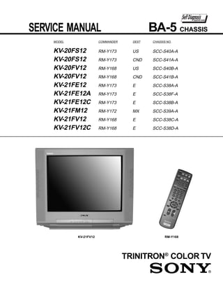
  • 1. SERVICE MANUAL BA-5 CHASSIS MODEL COMMANDER DEST CHASSIS NO. KV-20FS12 RM-Y173 US SCC-S40A-A KV-20FS12 RM-Y173 CND SCC-S41A-A KV-20FV12 RM-Y168 US SCC-S40B-A KV-20FV12 RM-Y168 CND SCC-S41B-A KV-21FE12 RM-Y173 E SCC-S38A-A KV-21FE12A RM-Y173 E SCC-S38F-A KV-21FE12C RM-Y173 E SCC-S38B-A KV-21FM12 RM-Y172 MX SCC-S39A-A KV-21FV12 RM-Y168 E SCC-S38C-A KV-21FV12C RM-Y168 E SCC-S38D-A KV-21FV12 RM-Y168 TRINITRON® COLOR TV
  • 2. KV-20FS12/20FV12/21FE12/A/C/21FM12/21FV12/C SPECIFICATIONS KV-21FE12 KV-21FE12A KV- 21FE12C KV-21FM12 KV-20FS12 KV-20FV12 KV-21FV12 KV-21FV12C Power requirements 120-220V, 50/60 Hz 120-220V, 50/60 Hz 120V,60Hz 120V,60Hz 120-220V, 50/60 Hz 120-220V, 50/60 Hz Number of inputs/outputs Video 1) 2 2 2 2 2 2 S Video 2) 1 1 1 1 1 1 Audio 3) 2 2 2 2 2 2 Audio Out 4) -- -- -- 1 1 1 Speaker output(W) 5W x 2 3W x 2 3W x 2 5W x 2 10W x 2 10W x 2 Power Consumption(W) In use(Max) 115W 115W 115W 150W 155W 150W In standby 1W 1W 1W 1W 1W 1W Dimensions(W/H/D) (mm) 512 x 475 x 493mm 512 x 475 x 493mm 512 x 475 x 493mm 562 x 466 x 503mm 562 x 466 x 503mm 562 x 466 x 503mm (in) 20 1/8 x 18 11/16 x 19 7/16 20 1/8 x 18 11/16 x 19 7/16 20 1/8 x 18 11/16 x 19 7/16 22 1/4 x 18 3/8 x 19 7/8 22 1/4 x 18 3/8 x 19 7/8 22 1/4 x 18 3/8 x 19 7/8 —2— Mass (kg) 24.5kg 24.5kg 24.5kg 27 kg 27 kg 27 kg (lbs) 54 lbs 54 lbs 54 lbs 59 lbs. 8 oz. 59 lbs. 8 oz. 59 lbs. 8 oz. 1) Vp-p 75 ohms unbalanced, sync negative 2) Y: 1 Vp-p 75 ohms unbalanced, sync negative Television system Supplied accessories C: 0.286 Vp-p (Burst signal), 75 ohms American TV standard/NTSC Remote Commander RM-Y168 (KV-20FV12/21FV12/21FV12C ONLY) 3) 500mVrms (100% modulation), impedance: 47kilohms PAL M, N (KV-21FE12A ONLY) Remote Commander RM-Y172 (KV-21FM12 ONLY) 4) More than 408 mVrms at the maximum volume setting (variable). More than 408 mVrms (fix). Remote Commander RM-Y173 (KV-20FS12/21FE12/21FE12A/21FE12C ONLY) Channel coverage Size AA (R6) batteries (2) VHF:2-13/UHF:14-69/CATV:1-125 Optional accessories Visible screen size Connecting cables: VMC-810S/820S, VMC-720M, YC-15V/30V, RK74A 20” picture measured diagonally U/V mixer EAC-66 Actual screen size 21” picture measured diagonally Antenna 75 ohm external antenna terminal for VHF/UHF Design and specifications are subject to change without notice.
  • 3. KV-20FS12/20FV12/21FE12/A/C/21FM12/21FV12/C TABLE OF CONTENTS Section Title Page Warnings and Cautions ............................................................................................................................................................... 4 Self-Diagnostic Function ............................................................................................................................................................. 4 Safety Check-Out Instructions .................................................................................................................................................... 7 1. GENERAL ........................................................................................................................................................... 8 2. DISASSEMBLY 2-1. Rear Cover Removal ..................................................................................................................................................... 13 2-2. Chassis Assembly Removal ......................................................................................................................................... 13 2-3. Service Position ............................................................................................................................................................ 13 2-4. Picture Tube Removal ................................................................................................................................................... 14 3. SET-UP ADJUSTMENTS 3-1. Beam Landing ............................................................................................................................................................... 15 3-2. Convergence ................................................................................................................................................................. 16 3-3. Focus ............................................................................................................................................................................. 17 3-4. Screen (G2) ................................................................................................................................................................... 17 3-5. Method of Setting the Service Adjustment Mode .............................................................................. ........................... 18 3-6. White Balance Adjustments .......................................................................................................................................... 18 4. SAFETY RELATED ADJUSTMENTS 4-1. R562 Confirmation Method (HV Hold-Down Confirmation and Readjustments) .................................................... 19 4-2. B+ Voltage Confirmation and Adjustment ..................................................................................................................... 19 5. CIRCUIT ADJUSTMENTS 5-1. Setting the Service Adjustment Mode .......................................................................................................................... 21 5-2. Memory Write Confirmation Method ............................................................................................................................. 21 5-3. Adjustment Buttons and Indicators ............................................................................................................................... 21 5-4. MB Board Adjustments ................................................................................................................................................. 23 6. DIAGRAMS 6-1. Block Diagram ............................................................................................................................................................... 27 6-2. Circuit Board Location .................................................................................................................................................. 30 6-3. Printed Wiring Boards and Schematic Diagrams ......................................................................................................... 30 • A Board .................................................................................................................................................................... 31 • K Board .................................................................................................................................................................... 38 • MB Board ................................................................................................................................................................. 39 • CB Board .................................................................................................................................................................. 47 • VB Board .................................................................................................................................................................. 49 • HZ Board .................................................................................................................................................................. 50 6-4. Semiconductors ............................................................................................................................................................ 51 7. EXPLODED VIEW 7-1. Chassis (KV-21FE12/C ONLY) .................................................................................................................................... 52 7-2. Chassis (KV-21FE12A MODEL ONLY) ......................................................................................................................... 53 7-3. Chassis (KV-20FV12/21FV12/C ONLY) ....................................................................................................................... 54 7-4. Chassis (KV-20FS12/21FM12 ONLY) .......................................................................................................................... 55 8. ELECTRICAL PARTS LIST ................................................................................................................................................. 56 —3—
  • 4. KV-20FS12/20FV12/21FE12/A/C/21FM12/21FV12/C WARNINGS AND CAUTIONS CAUTION ATTENTION!! SHORT CIRCUIT THE ANODE OF THE PICTURE TUBE APRES AVOIR DECONNECTE LE CAP DE L'ANODE, COURT-CIRCUITER AND THE ANODE CAP TO THE METAL CHASSIS, CRT L'ANODE DU TUBE CATHODIQUE ET CELUI DE L'ANODE DU CAP AU SHIELD, OR CARBON PAINTED ON THE CRT, AFTER CHASSIS METALLIQUE DE L'APPAREIL, OU AU COUCHE DE CARBONE REMOVING THE ANODE. PEINTE SUR LE TUBE CATHODIQUE OU AU BLINDAGE DU TUBE CATHODIQUE. WARNING!! ATTENTION!! AN ISOLATION TRANSFORMER SHOULD BE USED DURING ANY SERVICE TO AVOID POSSIBLE SHOCK AFIN D'EVITER TOUT RESQUE D'ELECTROCUTION PROVENANT D'UN HAZARD, BECAUSE OF LIVE CHASSIS. THE CHASSIS CHÁSSIS SOUS TENSION, UN TRANSFORMATEUR D'ISOLEMENT DOIT ETRE OF THIS RECEIVER IS DIRECTLY CONNECTED TO THE UTILISÉ LORS DE TOUT DÉPANNAGE. LE CHÁSSIS DE CE RÉCEPTEUR EST AC POWER LINE. DIRECTEMENT RACCORDÉ À L'ALIMENTATION SECTEUR. SAFETY-RELATED COMPONENT WARNING!! ATTENTION AUX COMPOSANTS RELATIFS A LA SECURITE!! COMPONENTS IDENTIFIED BY SHADING AND MARK LES COMPOSANTS IDENTIFIES PAR UNE TRAME ET PAR UNE MARQUE ON THE SCHEMATIC DIAGRAMS, EXPLODED VIEWS, SUR LES SCHEMAS DE PRINCIPE, LES VUES EXPLOSEES ET LES AND IN THE PARTS LIST ARE CRITICAL FOR SAFE LISTES DE PIECES SONT D'UNEIMPORTANCE CRITIQUE POUR LA OPERATION. REPLACE THESE COMPONENTS WITH SECURITE DU FONCTIONNEMENT. NE LES REMPLACER QUE PAR DES SONY PARTS WHOSE PART NUMBERS APPEAR AS COMPOSANTS SONY DONT LE NUMERO DE PIECE EST INDIQUE DANS SHOWN IN THIS MANUAL OR IN SUPPLEMENTS LE PRESENT MANUEL OU DANS DES SUPPLEMENTS PUBLIES PAR SONY. PUBLISHED BY SONY. CIRCUIT ADJUSTMENTS THAT LES REGLAGES DE CIRCUIT DONT L'IMPORTANCE EST CRITIQUE POUR ARE CRITICAL FOR SAFE OPERATION ARE IDENTIFIED LA SECURITE DU FONCTIONNEMENT SONT IDENTIFIES DANS LE IN THIS MANUAL. FOLLOW THESE PROCEDURES PRESENT MANUEL. SUIVRE CES PROCEDURES LORS DE CHAQUE WHENEVER CRITICAL COMPONENTS ARE REPLACED REMPLACEMENT DE COMPOSANTS CRITIQUES, OU LORSQU'UN OR IMPROPER OPERATION IS SUSPECTED. MAUVAIS FONTIONNEMENT SUSPECTE. SELF-DIAGNOSTIC FUNCTION The units in this manual contain a self-diagnostic function. If an error occurs, the STANDBY/TIMER LED will automatically begin to flash. The number of times the LED flashes translates to a probable source of the problem. A definition of the STANDBY/TIMER LED flash indicators is listed in the instruction manual for the user’s knowledge and reference. If an error symptom cannot be reproduced, the Remote Commander can be used to review the failure occurrence data stored in memory to reveal past problems and how often these problems occur. Diagnostic Test Indicators When an error occurs, the STANDBY/TIMER LED will flash a set number of times to indicate the possible cause of the problem. If there is more than one error, the LED will identify the first of the problem areas. Results for all of the following diagnostic items are displayed on screen. No error has occurred if the screen displays a “0”. No. of Times Diagnostic Item Self-Diagnostic Display/ Probable Cause STANDBY/TIMER Detected Symptoms Description Diagnostic Result Location LED Flashes Power does not turn on Does not light • Power cord is not plugged in. • Power does not come on. • Fuse is burned out. (F601) (A Board) • No power is supplied to the TV. • AC power supply is faulty. +B overcurrent (OCP)* 2 times 2:0 or 2:1 • H.OUT (Q502) is shorted. (A Board) • Power does not come on. • IC702 is shorted. (CB Board) • Load on power line is shorted. Vertical deflection stopped* 4 times 4:0 or 4:1 • +12V is not supplied. (A Board) • Has entered standby state after horizontal raster. • IC502 is faulty. (A Board) • Vertical deflection pulse is stopped. • Power line is shorted or power supply is stopped. White balance failure 5 times 5:0 or 5:1 • Video OUT (IC502) is faulty. (A Board) • No raster is generated. (not balanced) • IC1301 is faulty. (MB Board) • CRT cathode current detection reference • Screen (G2) is improperly adjusted.** pulse output is small. * If a +B overcurrent is detected, stoppage of the vertical deflection is detected simultaneously. The symptom that is diagnosed first by the microcontroller is displayed on the screen. ** Refer to Screen (G2) Adjustments in Section 3-4 of this manual. —4—
  • 5. KV-20FS12/20FV12/21FE12/A/C/21FM12/21FV12/C Display of Standby/Timer LED Flash Count 2 times 4 times 5 times LED ON 0.3 sec. STANDBY/TIMER LED LED OFF 0.3 sec. LED OFF 3 sec. Diagnostic Item Flash Count* +B overcurrent 2 times Vertical deflection stopped 4 times White balance failure 5 times *One flash count is not used for self-diagnostic. Stopping the Standby/Timer LED Flash Turn off the power switch on the TV main unit or unplug the power cord from the outlet to stop the STANDBY/TIMER LAMP from flashing. Self-Diagnostic Screen Display For errors with symptoms such as “power sometimes shuts off” or “screen sometimes goes out” that cannot be confirmed, it is possible to bring up past occurrences of failure on the screen for confirmation. To Bring Up Screen Test In standby mode, press buttons on the Remote Commander sequentially, in rapid succession, as shown below: Display Channel 5 Sound volume Power ON Note that this differs from entering the service mode (sound volume + ). Self-Diagnostic Screen Display SELF DIAGNOSTIC 2: 0 Numeral “0” means that no fault was detected. 3: N/A 0 4: 0 5: 1 Numeral “1” means a fault was detected one time only. 101: N/A 0 —5—
  • 6. KV-20FS12/20FV12/21FE12/A/C/21FM12/21FV12/C Handling of Self-Diagnostic Screen Display Since the diagnostic results displayed on the screen are not automatically cleared, always check the self-diagnostic screen during repairs. When you have completed the repairs, clear the result display to “0”. Unless the result display is cleared to “0”, the self-diagnostic function will not be able to detect subsequent faults after completion of the repairs. Clearing the Result Display To clear the result display to “0”, press buttons on the Remote Commander sequentially when the diagnostic screen is displayed, as shown below: Channel 8 ENTER Quitting the Self-Diagnostic Screen To quit the entire self-diagnostic screen, turn off the power switch on the Remote Commander or the main unit. Self-Diagnostic Circuit MB BOARD A BOARD MB BOARD MB BOARD IC1301 IC507 IC1001 IC1003 Y/CHROMA JUNGLE V. OUT SYSTEM MEMORY FROM 21 IK IN IO-BDAT 36 5 B-DAT CRT REF 3 17 I-PROT A BOARD FROM 18 HP/PROTECT IC502 PIN 7 O-LED 18 SDA 35 37 IO-SDAT DISPLAY +B overcurrent (OCP) Occurs when an overcurrent on the +B (135V) line is detected by pin 18 of IC1301 (MB Board). If the voltage of pin 18 of IC1301 (MB Board) is less than 1V when V.SYNC is more than seven verticals in a period, the unit will automatically turn off. Vertical deflection stopped Occurs when an absence of the vertical deflection pulse is detected by pin 17 of IC1001 (MB Board). Power supply will shut down when waveform interval exceeds 2 seconds. White balance failure If the RGB levels* do not balance within 2 seconds after the power is turned on, this error will be detected by IC1301 (MB Board). TV will stay on, but there will be no picture. *(Refers to the RGB levels of the AKB detection Ref pulse that detects 1K). —6—
  • 7. KV-20FS12/20FV12/21FE12/A/C/21FM12/21FV12/C SAFETY CHECK-OUT After correcting the original service problem, perform the Leakage Test following safety checks before releasing the set to the The AC leakage from any exposed metal part to earth customer: ground and from all exposed metal parts to any exposed metal part having a return to chassis, must not exceed 1. Check the area of your repair for unsoldered or poorly 0.5 mA (500 microamperes). Leakage current can be soldered connections. Check the entire board surface measured by any one of three methods. for solder splashes and bridges. 1. A commercial leakage tester, such as the Simpson 2. Check the interboard wiring to ensure that no wires 229 or RCA WT-540A. Follow the manufacturers' are “pinched” or touching high-wattage resistors. instructions to use these instructions. 3. Check that all control knobs, shields, covers, ground 2. A battery-operated AC milliammeter. The Data straps, and mounting hardware have been replaced. Precision 245 digital multimeter is suitable for this job. Be absolutely certain that you have replaced all the 3. Measuring the voltage drop across a resistor by insulators. means of a VOM or battery-operated AC voltmeter. 4. Look for unauthorized replacement parts, particularly The “limit” indication is 0.75 V, so analog meters must transistors, that were installed during a previous repair. have an accurate low voltage scale. The Simpson’s Point them out to the customer and recommend their 250 and Sanwa SH-63TRD are examples of passive replacement. VOMs that are suitable. Nearly all battery-operated 5. Look for parts which, though functioning, show digital multimeters that have a 2 VAC range are obvious signs of deterioration. Point them out to the suitable (see Figure A). customer and recommend their replacement. 6. Check the line cords for cracks and abrasion. How to Find a Good Earth Ground Recommend the replacement of any such line cord A cold-water pipe is a guaranteed earth ground; the cover- to the customer. plate retaining screw on most AC outlet boxes is also at 7. Check the B+ and HV to see if they are specified earth ground. If the retaining screw is to be used as your values. Make sure your instruments are accurate; earth ground, verify that it is at ground by measuring the be suspicious of your HV meter if sets always have resistance between it and a cold-water pipe with an low HV. ohmmeter. The reading should be zero ohms. If a cold-water 8. Check the antenna terminals, metal trim, “metallized” pipe is not accessible, connect a 60- to 100-watt trouble- knobs, screws, and all other exposed metal parts for light (not a neon lamp) between the hot side of the AC leakage. Check leakage as described below. receptacle and the retaining screw. Try both slots, if necessary, to locate the hot side on the line; the lamp should light at normal brilliance if the screw is at ground potential (see Figure B). Trouble Light Ohmmeter AC Outlet Box Cold-water Pipe Figure A. Using an AC voltmeter to check AC leakage. Figure B. Checking for earth ground. —7—
  • 8. KV-20FS12/20FV12/21FE12/A/C/21FM12/21FV12/C SECTION 1 GENERAL The instructions mentioned here are partial abstracts from the Operating Instruction Manual. Operating Instructions The page numbers shown reflect those of the Operating Instruction Manual. Connecting Additional Equipment Connecting Your TV TV and VCR Rear of TV Read this section before setting up your TV for the first time. This section covers basic connections in addition to any optional equipment you may be connecting. 2 Basic Connections Coaxial VCR TV with indoor or outdoor antenna, or CATV cable Cable Depending on the cable available in your home, choose one of the 1 From connections below: cable/ antenna 3 (Optional connection) —8— 1 Connect the coaxial cable from your TV antenna or cable service to the IN jack on your VCR. 2 Connect a coaxial cable (not supplied) from the OUT jack on your VCR to the VHF/UHF jack on the TV. To watch video programs from your VCR, tune your TV to channel 3 or 4 (as set on the rear of your VCR). (Optional connection) 3 If your VCR is equipped with video outputs, you can get better picture quality by connecting A/V cables (not supplied) from AUDIO and VIDEO OUT on your VCR to AUDIO/VIDEO IN on your TV. You can use the button to switch between the VHF/UHF and VIDEO inputs. If you are connecting to an indoor or outdoor antenna, you may need to adjust the orientation of the antenna for best reception. 3 4
  • 9. Connecting Your TV Operating Instructions TV and Cable Box TV, VCR, and Cable box Cable Box Rear of TV Coaxial Cable 1 From cable 3 VCR Coaxial 2 Cable Rear of TV 2 Cable box Coaxial Cable 4 (Optional connection) 1 From cable —9— 1 Connect the coaxial cable from your cable service to the IN jack on your cable box. 1 Connect the coaxial cable from your cable service to the IN jack on 2 Connect a coaxial cable (not supplied) from the OUT jack on your your cable box. cable box to the IN jack on your VCR. 2 Connect a coaxial cable (not supplied) from the OUT jack on your 3 Connect a coaxial cable (not supplied) from the OUT jack on your KV-20FS12/20FV12/21FE12/A/C/21FM12/21FV12/C cable box to the VHF/UHF jack on the TV. VCR to the VHF/UHF jack on the TV. To view channels from your cable box, tune your TV to channel 3 or 4 (as set If you will be controlling all channel selection through your cable box, you on the rear panel of your cable box) and use the cable box’s remote control to should consider using the Channel Fix feature, (see page 19). change channels. (Optional connection) If you will be controlling all channel selection through your cable box, you should consider using the Channel Fix feature, (see page 19). 4 If your VCR is equipped with video outputs, you can get better picture quality by connecting A/V cables (not supplied) from AUDIO and VIDEO OUT on your VCR to AUDIO/VIDEO IN on your TV. You can use the button to switch between the VHF/UHF and VIDEO inputs. 5 6
  • 10. KV-20FS12/20FV12/21FE12/A/C/21FM12/21FV12/C Connecting Your TV Operating Instructions TV and Satellite Receiver TV, Satellite Receiver, and VCR Rear of TV Satellite antenna 2 From cable Rear of TV cable/ antenna 1 4 From cable/ antenna VCR SATELLITE IN Satellite receiver VHF/UHF AUDIO R AUDIO L VIDEO IN AUDIO R AUDIO L VIDEO 2 1 SATELLITE IN VHF/UHF LINE OUT OUT LINE IN VHF/UHF IN AUDIO R AUDIO L VIDEO IN Satellite Satellite receiver LINE OUT OUT OUT antenna LINE OUT cable 3 5 3 1 Connect the cable from your satellite antenna to SATELLITE IN on your satellite receiver. — 10 — 2 Connect the coaxial cable from your cable service or antenna to the 1 Connect the cable from your satellite antenna to SATELLITE IN on IN jack on your VCR. your satellite receiver. 3 Using a coaxial cable, connect the OUT jack on your VCR to the 2 Connect the coaxial cable from your cable service or antenna to the VHF/UHF jack on your TV. VHF/UHF jack on your TV. 4 Using A/V cables, connect AUDIO and VIDEO OUT on your 3 Using A/V cables, connect AUDIO and VIDEO OUT on your satellite receiver to AUDIO and VIDEO IN on your VCR. satellite receiver to AUDIO and VIDEO IN on your TV. 5 Using A/V cables, connect AUDIO and VIDEO OUT on your VCR to AUDIO and VIDEO IN on your TV. You can use the button to switch between the VHF/UHF and VIDEO inputs. To view from the satellite receiver or VCR, select the video input to which your VCR is connected by pressing on the remote control. 7 8
  • 11. Operating Instructions Using the Remote Control and Basic Functions MENU Displays the on-screen menu. Press again to exit the menu at This section shows you how to use the more advanced buttons on the any time. remote control and how to use the on-screen menus. RESET Press to return to factory settings while in an on-screen menu. Using the Remote Control Button Description POWER Press when you want to turn the TV on and off. MUTING Instantly turns off the sound. Press again or press to restore MUTING SLEEP POWER sound. MTS/SAP DISPLAY TV/VIDEO TV/VIDEO Cycles through available video inputs. 1 2 3 Moves the cursor in the on- screen menus. Press the arrow 4 5 6 buttons to move the cursor. Press — 11 — 7 8 9 the center button to select or JUMP ENTER access an option. 0 VOL CH SLEEP Turns the TV off automatically in approximately 15, 30, 45, 60, or 90 minutes. Cancel by pressing until SLEEP OFF appears. RESET MENU MTS/SAP Cycles through the Multi- KV-20FS12/20FV12/21FE12/A/C/21FM12/21FV12/C channel TV Sound (MTS) options: Stereo, Mono, and Auto-SAP (Second Audio Programming) (KV-21FE12 RM-Y173 models only). DISPLAY Press to display the current time, TV (if set) and channel number. JUMP Alternates between the last two channels selected with the 0 9 buttons. The remote control illustrated (RM-Y173) is for KV-21FE12 models. For KV-21FM12 and KV-14FM12 models, your remote control does not have the MTS/SAP button. (Continued) 11 12
  • 12. KV-20FS12/20FV12/21FE12/A/C/21FM12/21FV12/C Operating Instructions Other Information Other Information Cannot receive higher number t Make sure Cable is set to OFF in the Options menu under Setup (page 23). channels (UHF) t Perform Auto Program to add channels that are not when using an Troubleshooting antenna presently in the memory (page 23). If you are having a problem with your TV, try the suggestions below. If Cable stations t Make sure Cable is set to ON in the Options menu the problem persists, contact your nearest Sony dealer. don’t seem to under Setup (page 23). work t Perform Auto Program to add channels that are not No picture, no t Make sure the power cord is plugged in. presently in the memory (page 23). sound t If a red light is flashing on the front of your TV for Remote control t Batteries could be weak. Replace them (page 2). more than a few minutes, disconnect and reconnect does not t Move the TV 3-4 feet or more away from fluorescent the power cord to restore the TV. If the problem operate lights. continues, call your local service center. t Check the TV/VIDEO settings: when watching TV, set The TV needs t Clean the TV with a soft dry cloth. Never use strong to TV; when watching video equipment, set to VIDEO to be cleaned solvents such as thinner or benzine, which might (page 11). damage the finish of the cabinet. t Make sure the batteries have been inserted correctly into the remote control. t Try another channel, it could be station trouble. — 12 — Poor or no t Adjust Picture in the Video menu (page 17). picture, good t Adjust Brightness in the Video menu (page 17). sound t Check the antenna and/or cable connections (page 3). MUTING Good picture, t Press so that MUTING disappears from the no sound screen (page 11). t Check your Audio settings. Your TV may be set to Auto-SAP (page 18). No color t Adjust Color in the Video menu (page 17). No signal t Check the Cable setting in the Options menu under Setup (page 23). t Check the antenna and/or cable connections (page 3). t Make sure the channel selected is currently broadcasting. Dotted lines or t Adjust the antenna. stripes t Move the TV away from other electronic equipment. Some electronic equipment can create electrical noise, which can interfere with TV reception. Double images t Check your outdoor antenna or call your cable service. or ghosts 24 25
  • 13. KV-20FS12/20FV12/21FE12/A/C/21FM12/21FV12/C SECTION 2 DISASSEMBLY 2-1. REAR COVER REMOVAL Screw +BVTP 4x16 Screw +BVTP 4x16 Rear Cover Screw +BVTP 4x16 Screw +BVTP 4x16 2 Screws +BVTP 4x12 2-2. CHASSIS ASSEMBLY REMOVAL 2-3. SERVICE POSITION CB Board VB Board CB Board MB Board VB Board MB Board Extension Cable A Board Claw A Board for Service p/n S-1294-965-A K Board K Board (KV-20FV12/21FV12/C ONLY) (KV-20FV12/21FV12/C ONLY) — 13 —
  • 14. KV-20FS12/20FV12/21FE12/A/C/21FM12/21FV12/C 2-4. PICTURE TUBE REMOVAL WARNING: BEFORE REMOVING 10 1 THE ANODE CAP High voltage remains in the CRT even after the power is disconnected. 2 To avoid electric shock, discharge CRT before attempting to remove the anode cap. Short between anode and 9 3 CRT coated earth ground strap. 8 7 6 Coated Earth 5 Ground Strap 4 1. Discharge the anode of the CRT and remove the anode cap. 6. Loosen the deflection yoke fixing screw and remove. 2. Unplug all interconnecting leads from the deflection yoke, neck 7. Place the set with the CRT face down on a cushion and remove assembly, degaussing coils and CRT grounding strap. the degaussing coil holders. 3. Remove the CB Board from the CRT. 8. Remove the degaussing coils. 4. Remove the chassis assembly. 9. Remove the CRT grounding strap and spring tentioners. 5. Loosen the neck assembly fixing screw and remove. 10. Unscrew the four CRT fixing screws [located on each CRT corner] and remove the CRT [Take care not to handle the CRT by the neck]. ANODE CAP REMOVAL WARNING: High voltage remains in the CRT even after the power is disconnected. To avoid electrical shock, discharge the CRT before attempting to remove the anode cap. Short between anode and coated earth ground strap of CRT. NOTE: After removing the anode, short circuit the anode of the picture tube and the anode cap to either the metal chassis, CRT shield, or carbon painted on the CRT. REMOVAL PROCEDURES c b a Anode Button 1 Turn up one side of the rubber cap in 2 Use your thumb to pull the rubber 3 When one side of the rubber cap the direction indicated by arrow a . cap firmly in the direction indicated separates from the anode button, by arrow b . the anode cap can be removed by turning the rubber cap and pulling it in the direction of arrow c . HOW TO HANDLE AN ANODE CAP 1 Do not use sharp objects which may cause damage to the surface of the anode cap. 2 To avoid damaging the anode cap, do not squeeze the rubber covering too hard. A material fitting called a shatter-hook terminal is built into the rubber. 3 Do not force turn the foot of the rubber cover. This may cause the shatter-hook terminal to protrude and damage the rubber. — 14 —
  • 15. KV-20FS12/20FV12/21FE12/A/C/21FM12/21FV12/C SECTION 3 SET-UP ADJUSTMENTS The following adjustments should be made when Perform the adjustments in order as follows: a complete realignment is required or when a new 1. Beam Landing picture tube is installed. 2. Convergence 3. Focus These adjustments should be performed with rated 4. Screen (G2) power supply voltage unless otherwise noted. 5. White Balance Set the controls as follows unless otherwise noted: Note: Test equipment required: VIDEO MODE: STANDARD • Color Bar Pattern Generator PICTURE control: ................ Normal • Degausser BRIGHTNESS control: ........ Normal • DC Power Supply • Digital Multimeter 3-1. BEAM LANDING 5. Move the deflection yoke forward and adjust so that the entire screen becomes green. Before beginning adjustment procedure: 1. Degauss the entire screen. 2. Feed in the white pattern signal. Adjustment Procedure 1. Input a raster signal with the pattern generator. 2. Loosen the deflection yoke mounting screw and set the purity control to the center as shown below. Purity Control 6. Switch over the raster signal to red and blue and confirm the condition. 7. When the position of the deflection yoke is determined, tighten it with the deflection yoke mounting screw. 8. If landing at the corner is not right, adjust by using the disk magnets. Purity control corrects this area 3. Turn the raster signal of the pattern generator to green. Disk magnets a b 4. Move the deflection yoke backward and adjust the purity or rotatable disk magnets correct control so that green is in the center and red and blue are these areas (a-d) c d at the sides evenly. Deflection yoke positioning corrects these areas Blue Red b Green d a c — 15 —
  • 16. KV-20FS12/20FV12/21FE12/A/C/21FM12/21FV12/C 3-2. CONVERGENCE Horizontal Static Convergence Before starting convergence adjustments: If the blue dot does not converge with the red and green dots, 1. Perform FOCUS, V.LIN AND V.SIZE adjustments. perform the following: 2. Set BRIGHTNESS control to minimum. 1. Move BMC magnet (a) to correct insufficient H. Static convergence. 3. Feed in dot pattern. 2. Rotate BMC magnet (b) to correct insufficient V. Static convergence. Vertical Static Convergence 3. After adjusting the BMC magnet, repeat Beam Landing 1. Adjust V.STAT magnet to converge red, green and blue dots in Adjustment. the center of the screen (Vertical movement adjust V.STAT RV to converge). V-STAT Center dot R G B BMC MAGNET R G B RV701 V.STAT PURITY V.STAT magnet b 2. Tilt the V.STAT magnet and adjust static convergence to open or close the V.STAT magnet. When the V.STAT magnet is moved in the direction of arrows a and b, red, green, and blue dots move as shown below: BMC magnet (1) a a b b b B B Dynamic Convergence Adjustment G G Before performing this adjustment, perform Horizontal R R and Vertical Static Convergence Adjustment. (2) 1. Slightly loosen deflection yoke screw. a R G B 2. Remove deflection yoke spacers. 3. Move the deflection yoke for best convergence as shown on the following page. b B G R (3) a b R B G G b B R — 16 —
  • 17. KV-20FS12/20FV12/21FE12/A/C/21FM12/21FV12/C 6. Adjust vertical red and blue convergence with V.TILT (TLV VR). R B G R B Perform adjustments while tracking items 1 and 2. G G B R G B R R G B B G R Screen-Corner Convergence 1. Affix a permalloy assembly corresponding to the B G R R G B misconverged areas. b a a b a-d: screen-corner misconvergence c d B R G B R G G R B G R B c d 4. Tighten the deflection yoke screw. 3-3. FOCUS 5. Install the deflection yoke spacers. 1. Adjust FOCUS control for best picture. TLH Plate Adjustment 1. Input crosshatch pattern. 2. Adjust PICTURE QUALITY to standard, PICTURE and BRIGHTNESS to 50%, and OTHER to standard. 3. Adjust the Horizontal Convergence of red and blue dots by tilting the TLH plate on the deflection yoke. Focus (FV) Screen (G2) 3-4. SCREEN (G2) 1. Input a dots pattern. 2. Set the PICTURE and BRIGHTNESS controls at minimum and COLOR control at normal. 3. Adjust SBRT, GCUT, BCUT in service mode with an oscilloscope as shown below so that voltages on the red, green, and blue cathodes are 170 VDC. BR RB TLH+ Pedestal (R)(B) (B)(R) TLH- 170 VDC Ground 4. Adjust XCV core to balance X axis. 4. Observe the screen and adjust SCREEN (G2) VR in FBT 5. Adjust YCH VR to balance Y axis. to obtain the faintly visible background of dot signal. — 17 —
  • 18. KV-20FS12/20FV12/21FE12/A/C/21FM12/21FV12/C 3-5. METHOD OF SETTING THE SERVICE ADJUSTMENT MODE Service Mode Procedure 1. Standby mode (power off). 2. Display Channel 5 Sound volume + Power on the Remote Commander (press each button within a second). Service Adjustment Mode In 1. The CRT displays the item being adjusted. Disp. Item (Item) Data SERVICE HSIZ 0 2. Press or on the Remote Commander to select the item. 3. Press or on the Remote Commander to change the data. 4. Press then to save into the memory. Service Adjustment Mode Memory Turn set off then on to exit service adjustment mode. SERVICE WRITE MUTING Green ENTER Red 3-6. WHITE BALANCE ADJUSTMENTS 1. Input an entire white signal with burst. 2. Set to Service Adjustment Mode. 3. Set DCOL to “0”. 4. Set the PICTURE and BRIGHTNESS to minimum. 5. Adjust with SBRT if necessary. 6. Select GCUT and BCUT with and . 7. Adjust with and for the best white balance. 8. Set PICTURE and BRIGHTNESS to maximum. 9. Select GDRV and BDRV with and . 10. Adjust with and for the best white balance. 11. Reset DCOL to “1”. 12. To write into memory, press then . — 18 —
  • 19. KV-20FS12/20FV12/21FE12/A/C/21FM12/21FV12/C SECTION 4 SAFETY RELATED ADJUSTMENTS 4-1. R562 CONFIRMATION METHOD Hold-Down Readjustment (HV HOLD-DOWN CONFIRMATION) AND If the setting indicated in step 2 of Hold-Down Operation READJUSTMENTS Confirmation cannot be met, readjustment should be performed by altering the resistance value of R562 component marked with . The following adjustments should always be performed when replacing the following components which are marked with on T505 FBT the schematic diagram: ammeter 3.0 mA DC Part Replaced ( ) Adjustment ( ) range ABL DY, T505, CRT, IC1301, IC501, HV HOLD-DOWN + A - C507, C520, C505, C509, C515, R562 T504, L508, C551, L510, C546, IABL C537, C547, D517, D518, D519, R560, R561, R562, R563, R565, R566, R567, R525 ..........A Board 4-2. B+ VOLTAGE CONFIRMATION AND ADJUSTMENT Preparation Before Confirmation Note: The following adjustments should always be performed 1. Using a Variac, apply AC input voltage: 120-220 ± 2 VAC. when replacing the following components, which are marked with on the schematic diagram on the G Board. 2. Turn the POWER switch ON. 3. Input a white signal and set the PICTURE and BRIGHTNESS controls to maximum. A BOARD: IC601, PH601 4. Confirm that the voltage between C546 (+) or TP503 and ground is more than 97 VDC. 1. Using a Variac, apply AC input voltage: 130 ± 2 VAC. 2. Input a dot signal. Hold-Down Operation Confirmation 3. Set the PICTURE and BRIGHTNESS controls to minimum. 1. Connect the current meter between Pin 11 of the FBT 4. Confirm that the voltage of A Board TP-600 is 136 VDC. (T505) and the PWB land where Pin 11 would normally 5. If step 3 is not satisfied, replace the components listed above, attach. (See Figure 1 on the next page.) then repeat steps 1–3. 2. Input a dot signal and set PICTURE and BRIGHTNESS to minimum: IABL = 100 ± 100 µA. 3. Confirm the voltage of A Board TP-600 is 135 ± 1 VDC. 4. Connect the digital voltmeter and the DC power supply via diode 1SS119 to C546 (+) and ground. (See Figure 1 on the next page.) 5. Increase the DC power voltage gradually until the picture blanks out. 6. Turn DC power source off immediately. 7. Read the digital voltmeter indication (standard 115.7 VDC). 8. Input a white signal and set PICTURE and BRIGHTNESS to maximum: IABL = 1350 ± 100 µA. 9. Repeat steps 4 to 7. — 19 —
  • 20. KV-20FS12/20FV12/21FE12/A/C/21FM12/21FV12/C DIGITAL POWER MULTIMETER SUPPLY + + – – 1SS119 R562 C546 T505 FBT ABL11 AMMETER 3mA dc range A + – Figure 1 — 20 —
  • 21. KV-20FS12/20FV12/21FE12/A/C/21FM12/21FV12/C SECTION 5 CIRCUIT ADJUSTMENTS ELECTRICAL ADJUSTMENTS BY REMOTE COMMANDER Use the Remote Commander (RM-Y168, RM-Y172 or RM-Y173) to perform the circuit adjustments in this section. NOTE: Test Equipment Required: • Pattern generator • Frequency counter • Digital multimeter • Audio oscillator 5-1. SETTING THE SERVICE ADJUSTMENT MODE 5-2. MEMORY WRITE CONFIRMATION METHOD 1. Standby mode (power off). 1. After adjustment, remove the power plug from the AC outlet, then plug it in again. 2. Display Channel 5 Sound volume + Power 2. Turn the power switch ON and set to service mode. on the Remote Commander (press each button within a second). 3. Call the adjusted items again to confirm they were adjusted. Service Adjustment Mode On 5-3. ADJUSTMENT BUTTONS AND INDICATORS (Use remote commander RM-Y168, RM-Y172 or RM-Y173.) 1. The CRT displays the item being adjusted. Disp. Item (Item) Data MUTING POWER SERVICE HSIZ 0 2. Press or on the Remote Commander to select an item. 3. Press or on the Remote Commander to change the data. 3 4. Press then to save into the memory. 5 DISPLAY Service Adjustment Mode Memory 6 1 SERVICE WRITE MUTING Green 4 ENTER 8 ENTER Red 1. Press then on the Remote Commander to initialize. VOLUME SERVICE RESET Carry out step 1 when adjusting IDs 0–4 and when replacing and adjusting IC1003. 2. Turn set off then on to exit service adjustment mode. RM-Y168 — 21 —
  • 22. KV-20FS12/20FV12/21FE12/A/C/21FM12/21FV12/C Adjustment Items FIX AVERAGE Reg # ITEM FUNCTION RANGE DATA NTSC PAL M PAL N VIDEO RF DATA 1 HSIZ Horizontal Size Adjustment 0-63 35 35 35 40 2 HPOS Horizontal Position Adjustment 0-63 33 33 33 25 3 VBOW Vertical Line Bowing Adj. 0-15 5 5 5 7 4 VANG Vertical line Bowing Slant Adj. 0-15 7 7 7 9 5 TRAP Horizontal Trapezoid Adj. 0-15 7 7 7 7 6 PAMP Horizontal PIN Distortion Adj. 0-63 7 7 7 12 7 UPIN Upper PIN Distortion Adj. 0-63 36 36 36 34 8 LPIN Lower PIN Distortion Adj. 0-63 36 36 36 37 9 VM Velocity Modulation On/Off 0,1 Palette mode controls this register 0 10 BLKO Vertical Blanking On/Off 0,1 0 0 11 VMLV Velocity Modulation Level 0-3 Palette mode controls this register 2 12 AGN2 Aging 2 0,1 0 0 13 REFP Reference Pulse Position 0,1 0 0 14 VBLK Vertical Blanking On/Off 0,3 0 0 15 JPSW 0,1 0 0 16 VSIZ Vertical Size Adjustment 0-63 40 47 47 26 17 VPOS Vertical Position Adj. 0-63 32 32 32 35 18 VLIN Vertical Linearity Adj. 0-15 7 5 19 SCOR Vertical S Correction Adjustment 0-15 6 4 20 VZOM 16:9 CRT Z Mode On/Off 0,1 0 0 21 EHT Vertical High-Voltage Correction 0-15 15 15 22 ASP Aspect Ratio Control 0-63 47 47 23 SCRL 16:9 CRT Z Mode Trans. Scroll 0-63 31 31 24 HBLK Horizontal Blanking On/Off 0,1 1 1 25 LBLK Left Blanking Adjustment 0-15 11 11 26 RBLK Right Blanking Adjustment 0-15 8 8 27 VUSN V Saw Waveform Compress 0,1 0 0 28 HDW Horizontal Drive Pulse Width 0,1 1 1 29 EWDC Parabola EW/ D.C. Adjustment 0.1 0 0 30 LVLN Lower Screen BTM Vertical Line Adj. 0-15 0 0 31 UVLN Upper Screen BTM Vertical Line Adj. 0-15 0 0 32 HTRAP Horizontal Trapezoid Adj. 0,1 **** 0 33 RDRV R Output Drive Control 0-63 31 21 34 GDRV G Output Drive Control 0-63 21 14 35 BDRV B Output Drive Control 0-63 21 14 36 RCUT R Output Cutoff Control 0-15 10 10 37 GCUT G Output Cutoff Control 0-15 6 7 38 BCUT B Output Cutoff Control 0-15 6 7 39 DCOL Dynamic Color On/Off 0,1 0 1 40 SHUE Sub HUE 0-31 12 14 41 SCOL Sub Color 0-31 14 14 14 14 42 SBRT Sub BRIGHTNESS 0-31 13 13 43 RON R Output On/Off 0,1 1 1 44 GON G Output On/Off 0,1 1 1 45 BON B Output On/Off 0,1 1 1 46 AXPL Axis PAL 0,1 0 0 47 AXNT Axis NTSC 0,1 0 1 48 CBPF Chroma BPF On/Off 0,1 1 1 49 CTRP Y TRAP FILTER On/Off 0,1 1 1 50 COFF Color On/Off 0,1 0 0 51 KOFF Set Color Killer 0,1 0 0 52 SSHP Sub SHARPNESS 0-15 5 5 53 SHPF SHARPNESS Circuit Fo 0,1 Palette mode controls this register 1 54 PREL Pre-Shoot / Over-Shoot 0,1 1 1 55 Y-DC DC Transmission Ratio Switching 0,1 Palette mode controls this register 1 56 GAMM Gamma Correction Amnt 0-3 Palette mode controls this register 1 57 ABLM ABL Mode Switching 0,1 1 1 58 VTH ABL CD VHT Switching 0,1 1 1 59 YDEL Y Delay Time Control 0-15 7 7 60 NCOL No Color ID 0,1 1 1 61 FSC FSC Out On/Off 0,1 1 1 62 K-ID Killer ID Control On/Off 0,1 0 0 63 HOSC Horizontal VCO Oscillation Freq. 0-15 12 12 — 22 —
  • 23. KV-20FS12/20FV12/21FE12/A/C/21FM12/21FV12/C FIX AVERAGE Reg # ITEM FUNCTION RANGE DATA NTSC PAL M PAL N VIDEO RF DATA 64 VSS Vertical Sync Slice Level 0,1 ** 0 65 HSS Horizontal Sync Slice Level 0,1 0 0 66 HMSK 0,1 0 0 67 VTMS Select Signal VTIM Pin 0-3 0 0 68 CDMD Vertical Count Down Mode Switching 0-3 3 *** 69 AFC AFC Loop Gain Switching 0-3 0 0 0 0 70 FIFR Field Frequency 0-3 * 3 71 SBAL Sub Balance 0-15 5 7 72 SBAS Sub Bass 0-7 0 9 73 STRE Sub Treble 0-7 3 9 74 BBEH BBE High 0-15 ***** 75 BBEL BBE Low 0-15 5 12 76 SRND Surround 0,1 0 13 77 AUX SRS, Simulated 0-3 0 78 DISP O.S.D Display Position 0-130 15 15 79 TROT Tilt Correction 0-63 31 31 31 80 HCLW Horizontal Count Lower Limit 0-255 16 16 16 81 HCHG Horizontal Count High Limit 0-255 64 64 64 82 SYSC Color System 0-7 4 6 83 VENH Vertical Enhancement 0-7 Palette mode controls this register 4 84 PDSO 0,1 0 85 CK 0,1 0 86 VNL 0-15 3 3 87 HPK 0,1 0 0 88 HPKO 0,1 Palette mode controls this register 89 CORE 0-3 1 1 90 TRAP 0,1 1 1 91 CHTR 0,1 0 0 92 CHPF 0,1 1 1 93 ENHO 0,1 0 0 94 ID0 0-225 25 SEE ID MAP 95 ID1 0-225 3 SEE ID MAP 96 ID2 0-225 91 SEE ID MAP 97 ID3 0-225 2 SEE ID MAP 98 ID4 0-225 233 SEE ID MAP 99 ID5 0-225 17 SEE ID MAP 100 ID6 0-225 0 SEE ID MAP * FIFR = 3 for NTSC models, FIFR=1 for Trinorma models ** VSS = 1 for US CND, VSS=0 for Other SERVICE ID0 25 *** CDMD = 3 for US CND, CDMD = 0 for Other **** KV-21FE12A,KV-21FE12C,KV-21FV12C=1; Others = 0 ***** BBE HIGH FIX DATA: KV-21FV12/21FV12C= 8; Others = 4 Notes: No. 1–100 show the order that each adjustment mode may be selected while in service mode. Data Range shows the range of possible settings for each adjustment mode. Initial Data shows the standard settings for each adjustment mode. ID MAP MODEL Destination ID-0 ID-1 ID-2 ID-3 ID-4 ID-5 ID-6 KV-21FM12 (MX) 17 3 88 2 233 17 0 KV-20FS12 (US) 89 3 75 50 137 17 0 KV-20FS12 (CND) 89 3 75 50 137 17 0 KV-21FE12 (E) 17 3 91 2 233 17 0 KV-21FE12A (E) 23 3 91 2 233 17 128 KV-21FE12C (E) 17 3 91 2 233 17 0 KV-20FV12 (US) 89 19 207 50 137 19 0 KV-20FV12 (CND) 89 19 207 50 137 19 0 KV-21FV12 (E) 17 19 223 2 233 19 0 KV-21FV12C (E) 17 19 223 2 233 19 0 — 23 —