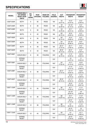
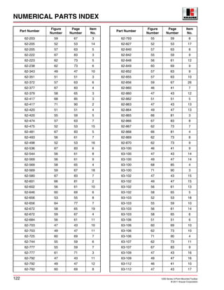
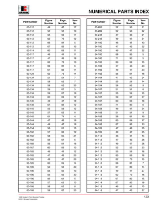
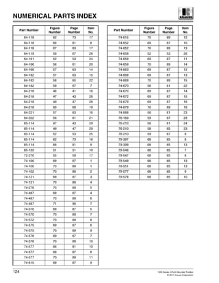
1200 Series
Ta GLADIATOR®
3-POINT MOUNTED
TOOLBAR MODELS
OWNER’S MANUAL
1200 Series 3-Point Mounted Toolbar i
© 2011 Kuhn Krause, Inc.
1200 Series 3-Point Mounted Toolbar
TABLE OF CONTENTS
Table of Contents..................................................................................... i
INTRODUCTION....................................................................................... 1
Congratulations ................................................................................... 1
Model Information................................................................................ 1
A Note to Our Customers, Parts Managers and Dealers: ............. 2
SAFETY .................................................................................................... 5
Safety Information ............................................................................... 5
Safety First .......................................................................................... 5
Safety Symbol Definitions.............................................................. 6
Before You Operate....................................................................... 6
Transporting Implement................................................................. 6
Operating and Maintaining Implement........................................... 7
Non-Operating and Storage of Implement..................................... 8
Safety Decals ...................................................................................... 9
Hand Signals ..................................................................................... 10
Ten Most Common Hand Signals Used in the Field.................... 10
SPECIFICATIONS .................................................................................. 11
1200 GLADIATOR® 3-Point Mounted Specifications ....................... 11
General Information........................................................................... 13
GLADIATOR® ST-PRO™........................................................... 14
GLADIATOR® ST-PRO™ S/R.................................................... 15
OPERATING INSTRUCTIONS............................................................... 17
About Your GLADIATOR®................................................................ 17
Preparing the GLADIATOR® for Field Operation.............................. 17
Preparing the Tractor ........................................................................ 18
Hydraulic System .............................................................................. 18
Hydraulic Safety (Please Read Carefully) ......................................... 18
Avoid Heating Near Pressurized Hydraulic Hoses ............................ 18
Hitching and Unhitching .................................................................... 19
Hitching to the Tractor ................................................................. 19
Unhitching from the Tractor......................................................... 19
Folding the Wings........................................................................ 20
Hydraulic Transport Lock Valves........................................... 21
Unfolding the Wings .................................................................... 21
Transporting ...................................................................................... 21
Adjustments Prior to Field Use.......................................................... 23
Relocating Row Unit Shipping Stop Pins..................................... 23
Setting the Gauge Wheels........................................................... 23
Adjustment and Lubrication of Hinges......................................... 23
Table of Contents
ii 1200 Series 3-Point Mounted Toolbar
© 2011 Kuhn Krause, Inc.
3-Point Top Link Adjustment ....................................................... 24
ST-PRO™ Row Unit Settings ........................................................... 24
Shank Depth Adjustment............................................................. 24
Krause Point, Side Shield and Fertilizer Tubes........................... 25
Shank and Adapter for other Points ............................................ 26
Closing Blade Adjustments ............................................................... 26
Closing Blade Float Limiter Settings ........................................... 26
Closing Blade Angle Settings...................................................... 26
Row Cleaner Weights ....................................................................... 28
Center Coulter Adjustments .............................................................. 28
Coulter Spring Pressure Adjustment........................................... 28
Coulter Depth Adjustment ........................................................... 28
Recommended Fertilizer Hose Routing ............................................ 29
Chain Reel ........................................................................................ 29
Field Operation.................................................................................. 29
Turning in the Field...................................................................... 29
Flexibility...................................................................................... 29
Field Speed ................................................................................. 29
Fertilizer Application.................................................................... 30
GPS Guidance ............................................................................ 30
Shear Bolt on ST-PRO™ Row Unit (Tension Bolt Trip Link)....... 30
Trail Hitch .................................................................................... 31
Hitching ....................................................................................... 31
Hitching to Lift Assist................................................................... 32
Lift Assist Adjustment.................................................................. 32
MAINTENANCE...................................................................................... 33
General Maintenance........................................................................ 33
Closing Blade Lock-Up...................................................................... 33
Ball Bearing Disassembly............................................................ 34
Ball Bearing Assembly ................................................................ 34
Composite Sleeve Disassembly.................................................. 34
Composite Sleeve Assembly....................................................... 34
Changing Fold Angle................................................................... 35
Removing Cylinder for Maintenance ........................................... 35
Cylinder Installation..................................................................... 35
Lubrication................................................................................... 36
Wheel Bearings........................................................................... 36
Storage........................................................................................ 36
Repair Parts ................................................................................ 36
TROUBLESHOOTING............................................................................ 37
Suggested Remedies for Possible Field Problems ........................... 37
PARTS SECTION................................................................................... 39
Hardware Part Name Definitions....................................................... 39
Rigid Toolbar Assemblies ................................................................. 40
Rigid Toolbar Assemblies Parts List............................................ 41
8-Row Folding Toolbar Assemblies .................................................. 42
8-Row Folding Toolbar Assemblies Parts List............................. 43
8-Row Folding Toolbar Assemblies (Cont.) ...................................... 44
8-Row Folding Toolbar Assemblies Parts List (Cont.)................. 45
12-Row Folding Toolbar Assemblies ................................................ 46
12-Row Folding Toolbar Assemblies Parts List........................... 47
Table of Contents
1200 Series 3-Point Mounted Toolbar iii
© 2011 Kuhn Krause, Inc.
12-Row Folding Toolbar Assemblies (Cont.)..................................... 48
12-Row Folding Toolbar Assemblies Parts List (Cont.)............... 49
Hydraulic Cylinder and Linkage Assembly ........................................ 50
Hydraulic Cylinder and Linkage Assembly Parts List .................. 51
Gauge Wheel Assembly.................................................................... 52
Gauge Wheel Assembly Parts List.............................................. 53
Folding Toolbars Hydraulic Diagram ................................................. 54
Folding Toolbars Hydraulic Diagram Parts List ........................... 55
Hydraulic Cylinder ............................................................................. 56
Hydraulic Cylinder Parts List ....................................................... 57
Row Frame & Reel Assy - Illustration................................................ 58
Row Frame & Reel Assy - Parts List ........................................... 59
Shank Pivot & Arm Assy - Illustration................................................ 60
Shank Pivot & Arm Assy - Parts List .......................................... 61
Coulter & Row Cleaner Assy - Illustration ......................................... 62
Coulter & Row Cleaner Assy - Parts List (Cont.)......................... 63
Shear Bolt Link & Closing Arm Assembly - Illustration...................... 64
Shear Bolt Link & Closing Arm Assy - Parts List ......................... 65
Spring Trip & Closing Arm Assy - Illustration .................................... 66
Spring Trip & Closing Arm Assy - Parts List................................ 67
Mounting Clamps, Shanks and Points .............................................. 68
Mounting Clamps, Shanks and Points Parts List......................... 69
Closing Blade Options....................................................................... 70
Closing Blade Options Parts List................................................. 71
Lift Assist Assembly .......................................................................... 72
Lift Assist Assembly Parts List..................................................... 73
Lift Assist Assembly (Cont.) .............................................................. 74
Lift Assist Assembly Parts List (Cont.)......................................... 75
Lift Assist Hydraulic Diagram ............................................................ 76
Lift Assist Hydraulic Diagram Parts List....................................... 77
Prince Hydraulic Cylinder .................................................................. 78
Prince Hydraulic Cylinder Parts List ............................................ 79
Trail Hitch Mounting Frame ............................................................... 80
Trail Hitch Mounting Frame Parts List ......................................... 81
Trail Hitch .......................................................................................... 82
Trail Hitch Parts List .................................................................... 83
Light Harness .................................................................................... 84
Light Harness Parts List .............................................................. 85
Decals and Reflectors ....................................................................... 86
Decals and Reflectors Parts List ................................................ 87
Decals and Reflectors ....................................................................... 88
Decals and Reflectors Parts List ................................................ 89
SMV Sign Assembly.......................................................................... 90
SMV Sign Assembly Parts List ................................................... 90
ASSEMBLY ............................................................................................ 91
Proper Bolt Use ................................................................................. 92
Krause 1200 3-Point Mounted GLADIATOR® .................................. 93
Assembly Instructions ....................................................................... 94
Assembly........................................................................................... 94
Assembly Steps................................................................................. 94
Model Numbers ................................................................................. 94
SPECIFICATIONS
12 1200 Series 3-Point Mounted Toolbar
© 2011 Kuhn Krause, Inc.
MODEL
SHEAR BOLT
OR SPRING
RESET ROW
UNITS
NO.
OF
ROWS
ROW
SPACING
RIGID OR
FOLDING
FOLD
DEGREE
CUT
WIDTH
TRANSPORT
WIDTH
TRANSPORT
HEIGHT
1200T-630R BOTH 6 30 RIGID NA
15'
(4.57 m)
14' 4"
(4.37 m)
8' 2"
(2.49 m)
1200T-636R BOTH 6 36 RIGID NA
18'
(5.49 m)
16' 10"
(5.13 m)
8' 2"
(2.49 m)
1200T-638R
BOTH 6 38 RIGID NA
19'
(5.79 m)
18' 1"
(5.51 m)
8' 2"
(2.49 m)
1200T-640R
BOTH 6 40 RIGID NA
20'
(6.10 m)
18' 6"
(5.64 m)
8' 2"
(2.49 m)
1200T-830R
BOTH 8 30 RIGID NA
20'
(6.10 m)
19' 4"
(5.89 m)
8' 2"
(2.49 m)
1200T-836R
BOTH 8 36 RIGID NA
24'
(7.32 m)
22' 10"
(6.96 m)
8' 2"
(2.49 m)
1200T-838R
BOTH 8 38 RIGID NA
25' 4"
(7.72 m)
25' 1"
(7.65 m)
8' 2"
(2.49 m)
1200T-840R
BOTH 8 40 RIGID NA
26' 8"
(8.13 m)
25' 2"
(7.67 m)
8' 2"
(2.49 m)
1200T-830F
SHEAR BOLT 8 30 FOLDING 160°
20'
(6.10 m)
11' 2"
(3.40 m)
10' 6"
(3.20 m)
SPRING
RESET
125°
15'
(4.57 m)
11'
(3.35 m)
1200T-836F
SHEAR BOLT 8 36 FOLDING 160°
24'
(7.32 m)
13' 7"
(4.14 m)
10' 8"
(3.25 m)
SPRING
RESET
125°
17' 5"
(5.31 m)
11' 5"
(3.48 m)
1200T-838F
SHEAR BOLT 8 38 FOLDING 160°
25' 4"
(7.72 m)
14' 11"
(4.55 m)
10' 8"
(3.25 m)
SPRING
RESET
125°
18' 9"
(5.72 m)
11' 5"
(3.48 m)
1200T-840F
SHEAR BOLT 8 40 FOLDING 160°
26' 8"
(8.13 m)
14' 11"
(4.55 m)
10' 11"
(3.33 m)
SPRING
RESET
125°
18' 9"
(5.72 m)
11' 10"
(3.61 m)
1200T-1230F
SHEAR BOLT 12 30 FOLDING 160°
30'
(9.14 m)
16' 1"
(4.90 m)
11' 4"
(3.45 m)
SPRING
RESET
125°
19' 10"
(6.05 m)
13'
(3.96 m)
1200T-1236F
SHEAR BOLT 12 36 FOLDING 160°
36'
(10.97 m)
19' 7"
(5.97 m)
11' 9"
(3.58 m)
SPRING
RESET
125°
23' 5"
(7.14 m)
13' 10"
(4.22 m)
1200T-1238F
SHEAR BOLT 12 38 FOLDING 160°
38'
(11.58 m)
21'
(6.40 m)
11' 9"
(3.58 m)
SPRING
RESET
125°
24' 9"
(7.54 m)
14'
(4.27 m)
1200T-1240F
SHEAR BOLT 12 40 FOLDING 160°
40'
(12.19 m)
21'
(6.40 m)
12' 1"
(3.68 m)
SPRING
RESET
125°
24' 9"
(7.54 m)
14' 9"
(4.50 m)
WARRANTY POLICY
114 1200 Series 3-Point Mounted Toolbar
© 2011 Kuhn Krause, Inc.
★[Kuhn Krause, Inc. will repair or replace, free of charge, any part of the product found to be defective,
within the specified warranty periods, after an inspection of the part has deemed it to be defective.
Inspection must be performed by an authorized agent of Kuhn Krause, Inc., or returned to the Krause
factory for inspection and disposition. Warranty labor will be considered during the first year of warranty
only. Kuhn Krause, Inc. will establish and publish an hourly flat rate for shop labor and reimbursement
during the first year of the warranty period. Kuhn Krause, Inc. does not allow credit for the cost of travel
time, mileage or hauling as a warranty allowance. During the remaining second and third year, when
applicable, Krause will repair or replace the defective part, without consideration of labor charges.]
4. Routine services (such as inspections, field settings, adjustments, etc.) and replacement of items
which deteriorate from expected normal wear and tear or exposure (such as paint, tires, hoses,
blades, sweeps, etc.) are not covered by this Limited Warranty. Such routine services and
replacements required during the course of operation are not considered to be the result of any
defect in the product.
B. LIMITATIONS APPLICABLE TO KRAUSE’S LIMITED WARRANTY.
1. This Warranty Policy only applies to equipment and parts sold in North America. Krause will be
relieved of all obligations and liability under this warranty if:
(a) The alleged defect in the part is due to misuse or neglect on the part of someone other than
Krause; or
(b) Krause’s identification mark or name or serial number has been removed from the part in question;
or
(c) The product and/or equipment have not been maintained, operated or stored either in accordance
with applicable manuals, communications or other written instructions of Krause or any
manufacturer of the part involved, or in accordance with applicable regulations and advisory
circulars unless buyer shows that such maintenance, operation or storage was not a contributory
cause of the defect; or
(d) The part in question has been modified or altered after delivery other than by the manufacturer or
in accordance with a modification or alternation scheme approved in writing by the manufacturer;
or
(e) The product is used for purposes other than conventional owner/operator usage. Usage not
considered conventional owner/operator includes, but is not limited to, operation conditions that
consist of rocks or other obstructions.
2. For the purpose of this Warranty, no part of the product or equipment will be regarded as breaching
the limited warranty merely because, subsequent to its delivery, some modification or alteration
becomes necessary for product improvements or in order to meet a change in the requirements of
any applicable regulation.
3. TO THE EXTENT ALLOWED BY APPLICABLE LAW, BUYER WAIVES AS TO KRAUSE ALL
OTHER WARRANTIES, WHETHER OF MERCHANTABILITY, FITNESS OR OTHERWISE, THERE
ARE NO WARRANTIES WHICH EXTEND BEYOND THE DESCRIPTION ON THE FACT HEREOF.
4. TO THE EXTENT ALLOWED BY APPLICABLE LAW, THE OBLIGATIONS OF KRAUSE SET
FORTH HEREIN SHALL BE THE EXCLUSIVE REMEDIES FOR ANY BREACH OF WARRANTY
HEREUNDER, AND, TO THE SAME EXTENT, KRAUSE SHALL NOT BE LIABLE FOR ANY
GENERAL, CONSEQUENTIAL OR INCIDENTAL DAMAGES, INCLUDING, WITHOUT LIMITATION,
ANY DAMAGES FOR DIMINUTION OF MARKET VALUE, LOSS OF USE OR LOSS OF PROFITS,
OR ANY DAMAGES TO THE PRODUCT CLAIMED BY BUYER OR ANY OTHER PERSON OR
ENTITY UPON THE THEORIES OF NEGLIGENCE OR STRICT LIABILITY IN TORT.
5. ANY ACTION BY BUYER FOR BREACH OF THISWARRANTY BY EITHER KRAUSE OR SELLER
MUST BE COMMENCED WITHIN (1) YEAR AFTER THE CAUSE OF ACTION ACCRUES.
NUMERICAL PARTS INDEX
118 1200 Series 3-Point Mounted Toolbar
© 2011 Krause Corporation
1010-325-1 46 41 21
1010-325-1 47 43 34
1010-325-1 49 47 32
1010-326-0 46 41 27
1010-327-0 46 41 27
1010-328-0 46 41 27
1010-329-0 46 41 27
1010-33-0 60 69 29
1010-33-0A 60 69 30
1010-33-2 60 69 31
1010-330-0 46 41 27
1010-331-0 48 45 56
1010-332-0 47 43 35
1010-333-0 51 51 11
1010-334-0 47 43 36
1010-334-0 49 47 33
1010-335-0 47 43 37
1010-335-0 49 47 34
1010-336-0 48 45 38
1010-336-0 49 47 35
1010-337-0 48 45 57
1010-338-0 48 45 56
1010-339-0 48 45 57
1010-34-0 56 61 33
1010-340-0 48 45 56
1010-341-0 48 45 57
1010-342-0 50 49 60
1010-342-0 50 49 60
1010-343-0 50 49 61
1010-343-1 49 47 36
1010-343-2 49 47 37
1010-344-0 50 49 62
1010-345-0 50 49 60
1010-345-0 50 49 60
1010-346-0 50 49 61
1010-348-0 50 49 60
1010-349-0 50 49 61
1010-35-0 55 59 22
1010-353-0 48 45 54
1010-354-0 48 45 55
1010-356-0 50 49 38
1010-357-0 50 49 39
1010-358-0 51 51 12
Part Number
Figure
Number
Page
Number
Item
No.
1010-358-0 53 55 9
1010-358-0 54 57 5
1010-358-1 54 57 2
1010-358-2 54 57 3
1010-358-3 54 57 4
1010-358-4 54 57 1
1010-360-0 50 49 58
1010-360-1 50 49 40
1010-360-1 67 83 18
1010-361-0 50 49 59
1010-362-0 50 49 58
1010-362-1 50 49 57
1010-363-0 50 49 59
1010-364-0 48 45 55
1010-364-1 48 45 39
1010-365-0 48 45 54
1010-366-0 48 45 55
1010-367-0 48 45 54
1010-368-0 48 45 55
1010-369-0 48 45 54
1010-370-0 66 81 11
1010-371-0 66 81 12
1010-372-0 66 81 13
1010-372-1 66 81 14
1010-373-0 66 81 15
1010-373-1 62 73 19
1010-373-1 66 81 16
1010-374-0 66 81 17
1010-375-0 66 81 18
1010-376-0 63 75 56
1010-377-0 63 75 56
1010-378-0 63 75 56
1010-379-0 63 75 56
1010-380-0 67 83 19
1010-381-0 67 83 20
1010-382-0 67 83 21
1010-383-0 67 83 22
1010-384-0 67 83 23
1010-386-0 62 73 20
1010-387-0 62 73 21
1010-388-0 62 73 22
1010-389-0 62 73 23
1010-390-0 62 73 24
Part Number
Figure
Number
Page
Number
Item
No.
NUMERICAL PARTS INDEX
1200 Series 3-Point Mounted Toolbar 119
© 2011 Krause Corporation
1010-391-0 62 73 25
1010-392-0 62 73 26
1010-393-0 62 73 27
1010-394-0 62 73 28
1010-395-0 62 73 29
1010-396-0 62 73 30
1010-397-0 62 73 31
1010-398-0 62 73 32
1010-398-1 63 75 33
1010-398-2 63 75 34
1010-398-3 63 75 35
1010-399-0 63 75 36
1010-399-1 63 75 37
1010-41-0 55 59 24
1010-41-1 55 59 25
1010-411-0 52 53 29
1010-411-1 52 53 32
1010-414-0 52 53 30
1010-419-0 52 53 31
1010-42-0 55 59 26
1010-420-1 50 49 41
1010-420-2 50 49 42
1010-420-3 50 49 43
1010-420-4 50 49 44
1010-420-5 48 45 43
1010-420-5 50 49 45
1010-420-5 70 89 17
1010-420-6 48 45 48
1010-420-6 50 49 46
1010-420-6 70 89 18
1010-433-1 67 83 24
1010-433-10 67 83 25
1010-433-2 67 83 26
1010-433-3 67 83 27
1010-433-4 67 83 28
1010-433-5 67 83 29
1010-433-6 67 83 30
1010-433-7 67 83 31
1010-433-8 67 83 32
1010-433-9 67 83 33
1010-439-1 63 75 38
1010-439-10 63 75 39
1010-439-11 63 75 40
Part Number
Figure
Number
Page
Number
Item
No.
1010-439-12 63 75 41
1010-439-13 63 75 42
1010-439-14 63 75 43
1010-439-15 63 75 44
1010-439-16 63 75 45
1010-439-2 63 75 46
1010-439-20 65 79 1
1010-439-21 65 79 7
1010-439-22 65 79 10
1010-439-3 63 75 47
1010-439-3 64 77 9
1010-439-5 63 75 49
1010-439-7 63 75 50
1010-439-8 63 75 51
1010-439-9 63 75 52
1010-44-0 57 63 21
1010-44-3 57 63 22
1010-440-0 63 75 57
1010-440-1 63 75 53
1010-441-0 63 75 57
1010-442-0 63 75 57
1010-443-0 63 75 57
1010-444-0 63 75 57
1010-446-0 63 75 56
1010-447-0 50 49 59
1010-448-0 50 49 58
1010-45-0 58 65 29
1010-45-0 59 67 14
1010-46-0 58 65 30
1010-46-0 59 67 15
1010-460-1 46 41 22
1010-460-1 48 45 40
1010-460-1 50 49 47
1010-460-2 46 41 23
1010-460-2 48 45 41
1010-460-2 50 49 48
1010-460-3 46 41 24
1010-460-3 48 45 42
1010-460-3 50 49 49
1010-460-4 46 41 25
1010-460-4 48 45 44
1010-460-4 50 49 50
1010-460-5 46 41 26
Part Number
Figure
Number
Page
Number
Item
No.
NUMERICAL PARTS INDEX
120 1200 Series 3-Point Mounted Toolbar
© 2011 Krause Corporation
1010-460-5 48 45 45
1010-460-5 50 49 51
1010-483-1 48 45 46
1010-483-10 51 51 13
1010-483-10 53 55 10
1010-483-11 51 51 14
1010-483-11 53 55 11
1010-483-12 48 45 47
1010-483-12 50 49 52
1010-483-13 51 51 15
1010-483-14 51 51 16
1010-483-15 51 51 17
1010-483-16 48 45 49
1010-483-16 50 49 53
1010-483-16 51 51 18
1010-483-16 67 83 34
1010-483-17 48 45 50
1010-483-17 63 75 54
1010-483-18 46 41 8
1010-483-18 48 45 51
1010-483-18 50 49 54
1010-483-2 51 51 19
1010-483-3 51 51 20
1010-483-4 51 51 21
1010-483-5 51 51 22
1010-483-6 51 51 23
1010-483-7 51 51 24
1010-483-8 48 45 52
1010-483-8 50 49 55
1010-483-9 48 45 53
1010-483-9 50 49 56
1010-52-0A 59 67 22
1010-52-2 59 67 30
1010-52-5 59 67 31
1010-52-6 59 67 32
1010-52-7 59 67 33
1010-52-8 59 67 34
1010-52-9A 59 67 35
1010-54-0 55 59 32
1010-54-0A 55 59 27
1010-56-0 55 59 28
1010-58-0 59 67 36
1010-59-0 60 69 32
Part Number
Figure
Number
Page
Number
Item
No.
1010-59-0A 60 69 33
1010-61-0A 60 69 34
1010-74-0 58 65 15
1010-74-0 59 67 23
1010-77-0A 59 67 37
1010-79-0 59 67 38
21-1042 62 73 1
21-1042 64 77 1
21-1042 65 79 A
21-286 65 79 8
21-337 65 79 4
21-404 65 79 11
21-497 65 79 3
21-857 65 79 19
21-878 65 79 5
21-879 65 79 6
21-907 65 79 2
24-2178R 53 55 13
24-2179R 53 55 14
24-2179R 64 77 10
24-2180R 53 55 14
24-2181R 53 55 16
24-2182R 53 55 16
24-2183R 64 77 11
24-5000R 53 55 15
24-5001R 53 55 15
24-5001R 53 55 17
24-5002R 53 55 17
24-576R 53 55 17
24-583R 53 55 15
25-1105 68 85 1
25-126 68 85 2
25-2250 64 77 3
25-2251 53 55 7
25-2251 64 77 4
25-2272 47 43 1
25-2272 49 47 1
25-2272 53 55 1
25-2289 53 55 4
25-2289 64 77 5
25-2290 53 55 5
25-2291 64 77 6
25-2550 53 55 6
Part Number
Figure
Number
Page
Number
Item
No.
NUMERICAL PARTS INDEX
122 1200 Series 3-Point Mounted Toolbar
© 2011 Krause Corporation
62-203 59 67 3
62-205 52 53 14
62-205 57 63 5
62-222 67 83 3
62-223 62 73 5
62-238 62 73 6
62-343 49 47 10
62-351 51 51 3
62-372 57 63 6
62-377 67 83 4
62-379 58 65 3
62-417 68 85 3
62-417 71 90 2
62-420 51 51 4
62-420 55 59 5
62-474 57 63 7
62-475 52 53 15
62-481 67 83 5
62-493 56 61 7
62-498 52 53 16
62-536 67 83 6
62-544 56 61 8
62-569 56 61 9
62-569 58 65 4
62-569 59 67 18
62-580 67 83 7
62-601 66 81 2
62-602 56 61 10
62-646 60 69 6
62-656 53 55 8
62-656 64 77 7
62-672 58 65 19
62-672 59 67 4
62-684 56 61 11
62-703 47 43 10
62-703 49 47 11
62-725 60 69 7
62-744 55 59 6
62-777 55 59 7
62-777 61 71 3
62-792 47 43 11
62-792 49 47 12
62-792 60 69 8
Part Number
Figure
Number
Page
Number
Item
No.
62-793 55 59 8
62-827 52 53 17
62-840 57 63 8
62-842 55 59 9
62-848 56 61 12
62-849 60 69 9
62-852 57 63 9
62-855 57 63 10
62-856 59 67 26
62-860 46 41 7
62-860 47 43 12
62-862 51 51 5
62-863 47 43 13
62-864 49 47 13
62-865 66 81 3
62-866 67 83 8
62-867 62 73 7
62-868 66 81 4
62-869 62 73 8
62-870 62 73 9
63-100 46 41 9
63-100 47 43 14
63-100 49 47 14
63-100 68 85 4
63-100 71 90 3
63-102 47 43 15
63-102 49 47 15
63-102 56 61 13
63-102 58 65 5
63-103 52 53 18
63-103 55 59 10
63-103 56 61 14
63-103 58 65 6
63-106 51 51 6
63-106 60 69 10
63-106 62 73 10
63-106 71 90 4
63-107 62 73 11
63-107 67 83 9
63-109 47 43 16
63-109 49 47 16
63-112 46 41 10
63-112 47 43 17
Part Number
Figure
Number
Page
Number
Item
No.
NUMERICAL PARTS INDEX
1200 Series 3-Point Mounted Toolbar 123
© 2011 Krause Corporation
63-112 49 47 17
63-112 52 53 19
63-112 55 59 11
63-112 62 73 12
63-112 66 81 5
63-112 67 83 10
63-114 60 69 11
63-117 46 41 11
63-117 47 43 18
63-117 62 73 13
63-117 66 81 6
63-117 67 83 11
63-129 62 73 14
63-134 51 51 7
63-134 58 65 7
63-134 58 65 20
63-134 59 67 5
63-134 59 67 19
63-134 60 69 12
63-135 49 47 18
63-139 67 83 12
63-140 55 59 12
63-140 57 63 11
63-140 61 71 4
63-144 47 43 19
63-144 49 47 19
63-154 56 61 15
63-162 57 63 12
63-162 58 65 21
63-162 59 67 6
63-166 56 61 16
63-167 60 69 13
63-185 46 41 12
63-185 47 43 20
63-185 49 47 20
63-185 60 69 14
63-186 52 53 20
63-186 55 59 13
63-186 55 59 30
63-186 56 61 17
63-186 57 63 13
63-186 58 65 8
63-186 59 67 20
Part Number
Figure
Number
Page
Number
Item
No.
63-201 52 53 21
63-209 52 53 22
63-245 47 43 21
63-245 49 47 21
64-100 46 41 13
64-100 47 43 22
64-100 49 47 22
64-100 68 85 5
64-100 71 90 5
64-102 60 69 15
64-103 47 43 23
64-103 49 47 23
64-103 56 61 18
64-104 47 43 24
64-104 55 59 14
64-104 58 65 9
64-107 51 51 8
64-107 55 59 15
64-107 59 67 27
64-107 60 69 16
64-107 71 90 6
64-108 49 47 24
64-108 51 51 9
64-108 56 61 19
64-108 60 69 17
64-108 67 83 13
64-109 47 43 25
64-109 49 47 25
64-112 46 41 14
64-112 47 43 26
64-112 49 47 26
64-112 52 53 23
64-112 55 59 16
64-112 60 69 18
64-112 62 73 15
64-112 66 81 7
64-112 67 83 14
64-113 49 47 27
64-113 62 73 16
64-113 67 83 15
64-114 67 83 16
64-118 46 41 15
64-118 47 43 27
Part Number
Figure
Number
Page
Number
Item
No.
Kuhn 1200 m 1236 Gladiator 3-point mounted toolbar models

Kuhn 1200 m 1236 Gladiator 3-point mounted toolbar models

  • 1.
    1200 Series Ta GLADIATOR® 3-POINTMOUNTED TOOLBAR MODELS OWNER’S MANUAL
  • 3.
    1200 Series 3-PointMounted Toolbar i © 2011 Kuhn Krause, Inc. 1200 Series 3-Point Mounted Toolbar TABLE OF CONTENTS Table of Contents..................................................................................... i INTRODUCTION....................................................................................... 1 Congratulations ................................................................................... 1 Model Information................................................................................ 1 A Note to Our Customers, Parts Managers and Dealers: ............. 2 SAFETY .................................................................................................... 5 Safety Information ............................................................................... 5 Safety First .......................................................................................... 5 Safety Symbol Definitions.............................................................. 6 Before You Operate....................................................................... 6 Transporting Implement................................................................. 6 Operating and Maintaining Implement........................................... 7 Non-Operating and Storage of Implement..................................... 8 Safety Decals ...................................................................................... 9 Hand Signals ..................................................................................... 10 Ten Most Common Hand Signals Used in the Field.................... 10 SPECIFICATIONS .................................................................................. 11 1200 GLADIATOR® 3-Point Mounted Specifications ....................... 11 General Information........................................................................... 13 GLADIATOR® ST-PRO™........................................................... 14 GLADIATOR® ST-PRO™ S/R.................................................... 15 OPERATING INSTRUCTIONS............................................................... 17 About Your GLADIATOR®................................................................ 17 Preparing the GLADIATOR® for Field Operation.............................. 17 Preparing the Tractor ........................................................................ 18 Hydraulic System .............................................................................. 18 Hydraulic Safety (Please Read Carefully) ......................................... 18 Avoid Heating Near Pressurized Hydraulic Hoses ............................ 18 Hitching and Unhitching .................................................................... 19 Hitching to the Tractor ................................................................. 19 Unhitching from the Tractor......................................................... 19 Folding the Wings........................................................................ 20 Hydraulic Transport Lock Valves........................................... 21 Unfolding the Wings .................................................................... 21 Transporting ...................................................................................... 21 Adjustments Prior to Field Use.......................................................... 23 Relocating Row Unit Shipping Stop Pins..................................... 23 Setting the Gauge Wheels........................................................... 23 Adjustment and Lubrication of Hinges......................................... 23
  • 4.
    Table of Contents ii1200 Series 3-Point Mounted Toolbar © 2011 Kuhn Krause, Inc. 3-Point Top Link Adjustment ....................................................... 24 ST-PRO™ Row Unit Settings ........................................................... 24 Shank Depth Adjustment............................................................. 24 Krause Point, Side Shield and Fertilizer Tubes........................... 25 Shank and Adapter for other Points ............................................ 26 Closing Blade Adjustments ............................................................... 26 Closing Blade Float Limiter Settings ........................................... 26 Closing Blade Angle Settings...................................................... 26 Row Cleaner Weights ....................................................................... 28 Center Coulter Adjustments .............................................................. 28 Coulter Spring Pressure Adjustment........................................... 28 Coulter Depth Adjustment ........................................................... 28 Recommended Fertilizer Hose Routing ............................................ 29 Chain Reel ........................................................................................ 29 Field Operation.................................................................................. 29 Turning in the Field...................................................................... 29 Flexibility...................................................................................... 29 Field Speed ................................................................................. 29 Fertilizer Application.................................................................... 30 GPS Guidance ............................................................................ 30 Shear Bolt on ST-PRO™ Row Unit (Tension Bolt Trip Link)....... 30 Trail Hitch .................................................................................... 31 Hitching ....................................................................................... 31 Hitching to Lift Assist................................................................... 32 Lift Assist Adjustment.................................................................. 32 MAINTENANCE...................................................................................... 33 General Maintenance........................................................................ 33 Closing Blade Lock-Up...................................................................... 33 Ball Bearing Disassembly............................................................ 34 Ball Bearing Assembly ................................................................ 34 Composite Sleeve Disassembly.................................................. 34 Composite Sleeve Assembly....................................................... 34 Changing Fold Angle................................................................... 35 Removing Cylinder for Maintenance ........................................... 35 Cylinder Installation..................................................................... 35 Lubrication................................................................................... 36 Wheel Bearings........................................................................... 36 Storage........................................................................................ 36 Repair Parts ................................................................................ 36 TROUBLESHOOTING............................................................................ 37 Suggested Remedies for Possible Field Problems ........................... 37 PARTS SECTION................................................................................... 39 Hardware Part Name Definitions....................................................... 39 Rigid Toolbar Assemblies ................................................................. 40 Rigid Toolbar Assemblies Parts List............................................ 41 8-Row Folding Toolbar Assemblies .................................................. 42 8-Row Folding Toolbar Assemblies Parts List............................. 43 8-Row Folding Toolbar Assemblies (Cont.) ...................................... 44 8-Row Folding Toolbar Assemblies Parts List (Cont.)................. 45 12-Row Folding Toolbar Assemblies ................................................ 46 12-Row Folding Toolbar Assemblies Parts List........................... 47
  • 5.
    Table of Contents 1200Series 3-Point Mounted Toolbar iii © 2011 Kuhn Krause, Inc. 12-Row Folding Toolbar Assemblies (Cont.)..................................... 48 12-Row Folding Toolbar Assemblies Parts List (Cont.)............... 49 Hydraulic Cylinder and Linkage Assembly ........................................ 50 Hydraulic Cylinder and Linkage Assembly Parts List .................. 51 Gauge Wheel Assembly.................................................................... 52 Gauge Wheel Assembly Parts List.............................................. 53 Folding Toolbars Hydraulic Diagram ................................................. 54 Folding Toolbars Hydraulic Diagram Parts List ........................... 55 Hydraulic Cylinder ............................................................................. 56 Hydraulic Cylinder Parts List ....................................................... 57 Row Frame & Reel Assy - Illustration................................................ 58 Row Frame & Reel Assy - Parts List ........................................... 59 Shank Pivot & Arm Assy - Illustration................................................ 60 Shank Pivot & Arm Assy - Parts List .......................................... 61 Coulter & Row Cleaner Assy - Illustration ......................................... 62 Coulter & Row Cleaner Assy - Parts List (Cont.)......................... 63 Shear Bolt Link & Closing Arm Assembly - Illustration...................... 64 Shear Bolt Link & Closing Arm Assy - Parts List ......................... 65 Spring Trip & Closing Arm Assy - Illustration .................................... 66 Spring Trip & Closing Arm Assy - Parts List................................ 67 Mounting Clamps, Shanks and Points .............................................. 68 Mounting Clamps, Shanks and Points Parts List......................... 69 Closing Blade Options....................................................................... 70 Closing Blade Options Parts List................................................. 71 Lift Assist Assembly .......................................................................... 72 Lift Assist Assembly Parts List..................................................... 73 Lift Assist Assembly (Cont.) .............................................................. 74 Lift Assist Assembly Parts List (Cont.)......................................... 75 Lift Assist Hydraulic Diagram ............................................................ 76 Lift Assist Hydraulic Diagram Parts List....................................... 77 Prince Hydraulic Cylinder .................................................................. 78 Prince Hydraulic Cylinder Parts List ............................................ 79 Trail Hitch Mounting Frame ............................................................... 80 Trail Hitch Mounting Frame Parts List ......................................... 81 Trail Hitch .......................................................................................... 82 Trail Hitch Parts List .................................................................... 83 Light Harness .................................................................................... 84 Light Harness Parts List .............................................................. 85 Decals and Reflectors ....................................................................... 86 Decals and Reflectors Parts List ................................................ 87 Decals and Reflectors ....................................................................... 88 Decals and Reflectors Parts List ................................................ 89 SMV Sign Assembly.......................................................................... 90 SMV Sign Assembly Parts List ................................................... 90 ASSEMBLY ............................................................................................ 91 Proper Bolt Use ................................................................................. 92 Krause 1200 3-Point Mounted GLADIATOR® .................................. 93 Assembly Instructions ....................................................................... 94 Assembly........................................................................................... 94 Assembly Steps................................................................................. 94 Model Numbers ................................................................................. 94
  • 18.
    SPECIFICATIONS 12 1200 Series3-Point Mounted Toolbar © 2011 Kuhn Krause, Inc. MODEL SHEAR BOLT OR SPRING RESET ROW UNITS NO. OF ROWS ROW SPACING RIGID OR FOLDING FOLD DEGREE CUT WIDTH TRANSPORT WIDTH TRANSPORT HEIGHT 1200T-630R BOTH 6 30 RIGID NA 15' (4.57 m) 14' 4" (4.37 m) 8' 2" (2.49 m) 1200T-636R BOTH 6 36 RIGID NA 18' (5.49 m) 16' 10" (5.13 m) 8' 2" (2.49 m) 1200T-638R BOTH 6 38 RIGID NA 19' (5.79 m) 18' 1" (5.51 m) 8' 2" (2.49 m) 1200T-640R BOTH 6 40 RIGID NA 20' (6.10 m) 18' 6" (5.64 m) 8' 2" (2.49 m) 1200T-830R BOTH 8 30 RIGID NA 20' (6.10 m) 19' 4" (5.89 m) 8' 2" (2.49 m) 1200T-836R BOTH 8 36 RIGID NA 24' (7.32 m) 22' 10" (6.96 m) 8' 2" (2.49 m) 1200T-838R BOTH 8 38 RIGID NA 25' 4" (7.72 m) 25' 1" (7.65 m) 8' 2" (2.49 m) 1200T-840R BOTH 8 40 RIGID NA 26' 8" (8.13 m) 25' 2" (7.67 m) 8' 2" (2.49 m) 1200T-830F SHEAR BOLT 8 30 FOLDING 160° 20' (6.10 m) 11' 2" (3.40 m) 10' 6" (3.20 m) SPRING RESET 125° 15' (4.57 m) 11' (3.35 m) 1200T-836F SHEAR BOLT 8 36 FOLDING 160° 24' (7.32 m) 13' 7" (4.14 m) 10' 8" (3.25 m) SPRING RESET 125° 17' 5" (5.31 m) 11' 5" (3.48 m) 1200T-838F SHEAR BOLT 8 38 FOLDING 160° 25' 4" (7.72 m) 14' 11" (4.55 m) 10' 8" (3.25 m) SPRING RESET 125° 18' 9" (5.72 m) 11' 5" (3.48 m) 1200T-840F SHEAR BOLT 8 40 FOLDING 160° 26' 8" (8.13 m) 14' 11" (4.55 m) 10' 11" (3.33 m) SPRING RESET 125° 18' 9" (5.72 m) 11' 10" (3.61 m) 1200T-1230F SHEAR BOLT 12 30 FOLDING 160° 30' (9.14 m) 16' 1" (4.90 m) 11' 4" (3.45 m) SPRING RESET 125° 19' 10" (6.05 m) 13' (3.96 m) 1200T-1236F SHEAR BOLT 12 36 FOLDING 160° 36' (10.97 m) 19' 7" (5.97 m) 11' 9" (3.58 m) SPRING RESET 125° 23' 5" (7.14 m) 13' 10" (4.22 m) 1200T-1238F SHEAR BOLT 12 38 FOLDING 160° 38' (11.58 m) 21' (6.40 m) 11' 9" (3.58 m) SPRING RESET 125° 24' 9" (7.54 m) 14' (4.27 m) 1200T-1240F SHEAR BOLT 12 40 FOLDING 160° 40' (12.19 m) 21' (6.40 m) 12' 1" (3.68 m) SPRING RESET 125° 24' 9" (7.54 m) 14' 9" (4.50 m)
  • 98.
    WARRANTY POLICY 114 1200Series 3-Point Mounted Toolbar © 2011 Kuhn Krause, Inc. ★[Kuhn Krause, Inc. will repair or replace, free of charge, any part of the product found to be defective, within the specified warranty periods, after an inspection of the part has deemed it to be defective. Inspection must be performed by an authorized agent of Kuhn Krause, Inc., or returned to the Krause factory for inspection and disposition. Warranty labor will be considered during the first year of warranty only. Kuhn Krause, Inc. will establish and publish an hourly flat rate for shop labor and reimbursement during the first year of the warranty period. Kuhn Krause, Inc. does not allow credit for the cost of travel time, mileage or hauling as a warranty allowance. During the remaining second and third year, when applicable, Krause will repair or replace the defective part, without consideration of labor charges.] 4. Routine services (such as inspections, field settings, adjustments, etc.) and replacement of items which deteriorate from expected normal wear and tear or exposure (such as paint, tires, hoses, blades, sweeps, etc.) are not covered by this Limited Warranty. Such routine services and replacements required during the course of operation are not considered to be the result of any defect in the product. B. LIMITATIONS APPLICABLE TO KRAUSE’S LIMITED WARRANTY. 1. This Warranty Policy only applies to equipment and parts sold in North America. Krause will be relieved of all obligations and liability under this warranty if: (a) The alleged defect in the part is due to misuse or neglect on the part of someone other than Krause; or (b) Krause’s identification mark or name or serial number has been removed from the part in question; or (c) The product and/or equipment have not been maintained, operated or stored either in accordance with applicable manuals, communications or other written instructions of Krause or any manufacturer of the part involved, or in accordance with applicable regulations and advisory circulars unless buyer shows that such maintenance, operation or storage was not a contributory cause of the defect; or (d) The part in question has been modified or altered after delivery other than by the manufacturer or in accordance with a modification or alternation scheme approved in writing by the manufacturer; or (e) The product is used for purposes other than conventional owner/operator usage. Usage not considered conventional owner/operator includes, but is not limited to, operation conditions that consist of rocks or other obstructions. 2. For the purpose of this Warranty, no part of the product or equipment will be regarded as breaching the limited warranty merely because, subsequent to its delivery, some modification or alteration becomes necessary for product improvements or in order to meet a change in the requirements of any applicable regulation. 3. TO THE EXTENT ALLOWED BY APPLICABLE LAW, BUYER WAIVES AS TO KRAUSE ALL OTHER WARRANTIES, WHETHER OF MERCHANTABILITY, FITNESS OR OTHERWISE, THERE ARE NO WARRANTIES WHICH EXTEND BEYOND THE DESCRIPTION ON THE FACT HEREOF. 4. TO THE EXTENT ALLOWED BY APPLICABLE LAW, THE OBLIGATIONS OF KRAUSE SET FORTH HEREIN SHALL BE THE EXCLUSIVE REMEDIES FOR ANY BREACH OF WARRANTY HEREUNDER, AND, TO THE SAME EXTENT, KRAUSE SHALL NOT BE LIABLE FOR ANY GENERAL, CONSEQUENTIAL OR INCIDENTAL DAMAGES, INCLUDING, WITHOUT LIMITATION, ANY DAMAGES FOR DIMINUTION OF MARKET VALUE, LOSS OF USE OR LOSS OF PROFITS, OR ANY DAMAGES TO THE PRODUCT CLAIMED BY BUYER OR ANY OTHER PERSON OR ENTITY UPON THE THEORIES OF NEGLIGENCE OR STRICT LIABILITY IN TORT. 5. ANY ACTION BY BUYER FOR BREACH OF THISWARRANTY BY EITHER KRAUSE OR SELLER MUST BE COMMENCED WITHIN (1) YEAR AFTER THE CAUSE OF ACTION ACCRUES.
  • 102.
    NUMERICAL PARTS INDEX 1181200 Series 3-Point Mounted Toolbar © 2011 Krause Corporation 1010-325-1 46 41 21 1010-325-1 47 43 34 1010-325-1 49 47 32 1010-326-0 46 41 27 1010-327-0 46 41 27 1010-328-0 46 41 27 1010-329-0 46 41 27 1010-33-0 60 69 29 1010-33-0A 60 69 30 1010-33-2 60 69 31 1010-330-0 46 41 27 1010-331-0 48 45 56 1010-332-0 47 43 35 1010-333-0 51 51 11 1010-334-0 47 43 36 1010-334-0 49 47 33 1010-335-0 47 43 37 1010-335-0 49 47 34 1010-336-0 48 45 38 1010-336-0 49 47 35 1010-337-0 48 45 57 1010-338-0 48 45 56 1010-339-0 48 45 57 1010-34-0 56 61 33 1010-340-0 48 45 56 1010-341-0 48 45 57 1010-342-0 50 49 60 1010-342-0 50 49 60 1010-343-0 50 49 61 1010-343-1 49 47 36 1010-343-2 49 47 37 1010-344-0 50 49 62 1010-345-0 50 49 60 1010-345-0 50 49 60 1010-346-0 50 49 61 1010-348-0 50 49 60 1010-349-0 50 49 61 1010-35-0 55 59 22 1010-353-0 48 45 54 1010-354-0 48 45 55 1010-356-0 50 49 38 1010-357-0 50 49 39 1010-358-0 51 51 12 Part Number Figure Number Page Number Item No. 1010-358-0 53 55 9 1010-358-0 54 57 5 1010-358-1 54 57 2 1010-358-2 54 57 3 1010-358-3 54 57 4 1010-358-4 54 57 1 1010-360-0 50 49 58 1010-360-1 50 49 40 1010-360-1 67 83 18 1010-361-0 50 49 59 1010-362-0 50 49 58 1010-362-1 50 49 57 1010-363-0 50 49 59 1010-364-0 48 45 55 1010-364-1 48 45 39 1010-365-0 48 45 54 1010-366-0 48 45 55 1010-367-0 48 45 54 1010-368-0 48 45 55 1010-369-0 48 45 54 1010-370-0 66 81 11 1010-371-0 66 81 12 1010-372-0 66 81 13 1010-372-1 66 81 14 1010-373-0 66 81 15 1010-373-1 62 73 19 1010-373-1 66 81 16 1010-374-0 66 81 17 1010-375-0 66 81 18 1010-376-0 63 75 56 1010-377-0 63 75 56 1010-378-0 63 75 56 1010-379-0 63 75 56 1010-380-0 67 83 19 1010-381-0 67 83 20 1010-382-0 67 83 21 1010-383-0 67 83 22 1010-384-0 67 83 23 1010-386-0 62 73 20 1010-387-0 62 73 21 1010-388-0 62 73 22 1010-389-0 62 73 23 1010-390-0 62 73 24 Part Number Figure Number Page Number Item No.
  • 103.
    NUMERICAL PARTS INDEX 1200Series 3-Point Mounted Toolbar 119 © 2011 Krause Corporation 1010-391-0 62 73 25 1010-392-0 62 73 26 1010-393-0 62 73 27 1010-394-0 62 73 28 1010-395-0 62 73 29 1010-396-0 62 73 30 1010-397-0 62 73 31 1010-398-0 62 73 32 1010-398-1 63 75 33 1010-398-2 63 75 34 1010-398-3 63 75 35 1010-399-0 63 75 36 1010-399-1 63 75 37 1010-41-0 55 59 24 1010-41-1 55 59 25 1010-411-0 52 53 29 1010-411-1 52 53 32 1010-414-0 52 53 30 1010-419-0 52 53 31 1010-42-0 55 59 26 1010-420-1 50 49 41 1010-420-2 50 49 42 1010-420-3 50 49 43 1010-420-4 50 49 44 1010-420-5 48 45 43 1010-420-5 50 49 45 1010-420-5 70 89 17 1010-420-6 48 45 48 1010-420-6 50 49 46 1010-420-6 70 89 18 1010-433-1 67 83 24 1010-433-10 67 83 25 1010-433-2 67 83 26 1010-433-3 67 83 27 1010-433-4 67 83 28 1010-433-5 67 83 29 1010-433-6 67 83 30 1010-433-7 67 83 31 1010-433-8 67 83 32 1010-433-9 67 83 33 1010-439-1 63 75 38 1010-439-10 63 75 39 1010-439-11 63 75 40 Part Number Figure Number Page Number Item No. 1010-439-12 63 75 41 1010-439-13 63 75 42 1010-439-14 63 75 43 1010-439-15 63 75 44 1010-439-16 63 75 45 1010-439-2 63 75 46 1010-439-20 65 79 1 1010-439-21 65 79 7 1010-439-22 65 79 10 1010-439-3 63 75 47 1010-439-3 64 77 9 1010-439-5 63 75 49 1010-439-7 63 75 50 1010-439-8 63 75 51 1010-439-9 63 75 52 1010-44-0 57 63 21 1010-44-3 57 63 22 1010-440-0 63 75 57 1010-440-1 63 75 53 1010-441-0 63 75 57 1010-442-0 63 75 57 1010-443-0 63 75 57 1010-444-0 63 75 57 1010-446-0 63 75 56 1010-447-0 50 49 59 1010-448-0 50 49 58 1010-45-0 58 65 29 1010-45-0 59 67 14 1010-46-0 58 65 30 1010-46-0 59 67 15 1010-460-1 46 41 22 1010-460-1 48 45 40 1010-460-1 50 49 47 1010-460-2 46 41 23 1010-460-2 48 45 41 1010-460-2 50 49 48 1010-460-3 46 41 24 1010-460-3 48 45 42 1010-460-3 50 49 49 1010-460-4 46 41 25 1010-460-4 48 45 44 1010-460-4 50 49 50 1010-460-5 46 41 26 Part Number Figure Number Page Number Item No.
  • 104.
    NUMERICAL PARTS INDEX 1201200 Series 3-Point Mounted Toolbar © 2011 Krause Corporation 1010-460-5 48 45 45 1010-460-5 50 49 51 1010-483-1 48 45 46 1010-483-10 51 51 13 1010-483-10 53 55 10 1010-483-11 51 51 14 1010-483-11 53 55 11 1010-483-12 48 45 47 1010-483-12 50 49 52 1010-483-13 51 51 15 1010-483-14 51 51 16 1010-483-15 51 51 17 1010-483-16 48 45 49 1010-483-16 50 49 53 1010-483-16 51 51 18 1010-483-16 67 83 34 1010-483-17 48 45 50 1010-483-17 63 75 54 1010-483-18 46 41 8 1010-483-18 48 45 51 1010-483-18 50 49 54 1010-483-2 51 51 19 1010-483-3 51 51 20 1010-483-4 51 51 21 1010-483-5 51 51 22 1010-483-6 51 51 23 1010-483-7 51 51 24 1010-483-8 48 45 52 1010-483-8 50 49 55 1010-483-9 48 45 53 1010-483-9 50 49 56 1010-52-0A 59 67 22 1010-52-2 59 67 30 1010-52-5 59 67 31 1010-52-6 59 67 32 1010-52-7 59 67 33 1010-52-8 59 67 34 1010-52-9A 59 67 35 1010-54-0 55 59 32 1010-54-0A 55 59 27 1010-56-0 55 59 28 1010-58-0 59 67 36 1010-59-0 60 69 32 Part Number Figure Number Page Number Item No. 1010-59-0A 60 69 33 1010-61-0A 60 69 34 1010-74-0 58 65 15 1010-74-0 59 67 23 1010-77-0A 59 67 37 1010-79-0 59 67 38 21-1042 62 73 1 21-1042 64 77 1 21-1042 65 79 A 21-286 65 79 8 21-337 65 79 4 21-404 65 79 11 21-497 65 79 3 21-857 65 79 19 21-878 65 79 5 21-879 65 79 6 21-907 65 79 2 24-2178R 53 55 13 24-2179R 53 55 14 24-2179R 64 77 10 24-2180R 53 55 14 24-2181R 53 55 16 24-2182R 53 55 16 24-2183R 64 77 11 24-5000R 53 55 15 24-5001R 53 55 15 24-5001R 53 55 17 24-5002R 53 55 17 24-576R 53 55 17 24-583R 53 55 15 25-1105 68 85 1 25-126 68 85 2 25-2250 64 77 3 25-2251 53 55 7 25-2251 64 77 4 25-2272 47 43 1 25-2272 49 47 1 25-2272 53 55 1 25-2289 53 55 4 25-2289 64 77 5 25-2290 53 55 5 25-2291 64 77 6 25-2550 53 55 6 Part Number Figure Number Page Number Item No.
  • 106.
    NUMERICAL PARTS INDEX 1221200 Series 3-Point Mounted Toolbar © 2011 Krause Corporation 62-203 59 67 3 62-205 52 53 14 62-205 57 63 5 62-222 67 83 3 62-223 62 73 5 62-238 62 73 6 62-343 49 47 10 62-351 51 51 3 62-372 57 63 6 62-377 67 83 4 62-379 58 65 3 62-417 68 85 3 62-417 71 90 2 62-420 51 51 4 62-420 55 59 5 62-474 57 63 7 62-475 52 53 15 62-481 67 83 5 62-493 56 61 7 62-498 52 53 16 62-536 67 83 6 62-544 56 61 8 62-569 56 61 9 62-569 58 65 4 62-569 59 67 18 62-580 67 83 7 62-601 66 81 2 62-602 56 61 10 62-646 60 69 6 62-656 53 55 8 62-656 64 77 7 62-672 58 65 19 62-672 59 67 4 62-684 56 61 11 62-703 47 43 10 62-703 49 47 11 62-725 60 69 7 62-744 55 59 6 62-777 55 59 7 62-777 61 71 3 62-792 47 43 11 62-792 49 47 12 62-792 60 69 8 Part Number Figure Number Page Number Item No. 62-793 55 59 8 62-827 52 53 17 62-840 57 63 8 62-842 55 59 9 62-848 56 61 12 62-849 60 69 9 62-852 57 63 9 62-855 57 63 10 62-856 59 67 26 62-860 46 41 7 62-860 47 43 12 62-862 51 51 5 62-863 47 43 13 62-864 49 47 13 62-865 66 81 3 62-866 67 83 8 62-867 62 73 7 62-868 66 81 4 62-869 62 73 8 62-870 62 73 9 63-100 46 41 9 63-100 47 43 14 63-100 49 47 14 63-100 68 85 4 63-100 71 90 3 63-102 47 43 15 63-102 49 47 15 63-102 56 61 13 63-102 58 65 5 63-103 52 53 18 63-103 55 59 10 63-103 56 61 14 63-103 58 65 6 63-106 51 51 6 63-106 60 69 10 63-106 62 73 10 63-106 71 90 4 63-107 62 73 11 63-107 67 83 9 63-109 47 43 16 63-109 49 47 16 63-112 46 41 10 63-112 47 43 17 Part Number Figure Number Page Number Item No.
  • 107.
    NUMERICAL PARTS INDEX 1200Series 3-Point Mounted Toolbar 123 © 2011 Krause Corporation 63-112 49 47 17 63-112 52 53 19 63-112 55 59 11 63-112 62 73 12 63-112 66 81 5 63-112 67 83 10 63-114 60 69 11 63-117 46 41 11 63-117 47 43 18 63-117 62 73 13 63-117 66 81 6 63-117 67 83 11 63-129 62 73 14 63-134 51 51 7 63-134 58 65 7 63-134 58 65 20 63-134 59 67 5 63-134 59 67 19 63-134 60 69 12 63-135 49 47 18 63-139 67 83 12 63-140 55 59 12 63-140 57 63 11 63-140 61 71 4 63-144 47 43 19 63-144 49 47 19 63-154 56 61 15 63-162 57 63 12 63-162 58 65 21 63-162 59 67 6 63-166 56 61 16 63-167 60 69 13 63-185 46 41 12 63-185 47 43 20 63-185 49 47 20 63-185 60 69 14 63-186 52 53 20 63-186 55 59 13 63-186 55 59 30 63-186 56 61 17 63-186 57 63 13 63-186 58 65 8 63-186 59 67 20 Part Number Figure Number Page Number Item No. 63-201 52 53 21 63-209 52 53 22 63-245 47 43 21 63-245 49 47 21 64-100 46 41 13 64-100 47 43 22 64-100 49 47 22 64-100 68 85 5 64-100 71 90 5 64-102 60 69 15 64-103 47 43 23 64-103 49 47 23 64-103 56 61 18 64-104 47 43 24 64-104 55 59 14 64-104 58 65 9 64-107 51 51 8 64-107 55 59 15 64-107 59 67 27 64-107 60 69 16 64-107 71 90 6 64-108 49 47 24 64-108 51 51 9 64-108 56 61 19 64-108 60 69 17 64-108 67 83 13 64-109 47 43 25 64-109 49 47 25 64-112 46 41 14 64-112 47 43 26 64-112 49 47 26 64-112 52 53 23 64-112 55 59 16 64-112 60 69 18 64-112 62 73 15 64-112 66 81 7 64-112 67 83 14 64-113 49 47 27 64-113 62 73 16 64-113 67 83 15 64-114 67 83 16 64-118 46 41 15 64-118 47 43 27 Part Number Figure Number Page Number Item No.