SlideShare a Scribd company logo
00-1
SEBM035005
© 2007
All Rights Reserved
Printed in Japan 11-07 (01) (5)
MACHINE MODEL SERIAL NUMBER
D31EX-21 50501 and up
D31PX-21 50501 and up
D37EX-21 5501 and up
D37PX-21 5501 and up
D39EX-21 1501 and up
D39PX-21 1501 and up
• This shop manual may contain attachments and optional equipment that are not available
in your area. Please consult your local Komatsu distributor for those items you may
require. Materials and specifications are subject to change without notice.
• D31, D37, D39EX, PX-21 mount the SAA4D102E-2 engine.
For details of the engine, see the 102 Series Engine Shop Manual.
00-2 D31/37/39EX, PX-21
GENERAL
(1)
CONTENTS
No. of page
01 GENERAL ................................................................................................................................ 01-1
10 STRUCTURE AND FUNCTION,
MAINTENANCE STANDARD..................................................... 10-1
20 TESTING AND ADJUSTING................................................................................... 20-1
30 DISASSEMBLY AND ASSEMBLY ................................................................... 30-1
90 OTHERS..................................................................................................................................... 90-1
D31/37/39EX, PX-21 30-9
DISASSEMBLY AND ASSEMBLY FUEL INJECTION PUMP
(1)
REMOVAL AND
INSTALLATION OF FUEL
INJECTION PUMP ASSEMBLY
SPECIAL TOOLS
REMOVAL
1. Open up both engine hoods (1).
2. Remove left engine side cover (2).
3. Close the fuel stop valve.
4. Disconnect fuel control linkage (3). [*1]
5. Disconnect decelerator pedal linkage (4). [*2]
6. Remove engine stop solenoid (5). [*3]
7. Disconnect air tube (6).
8. Disconnect fuel inlet hoses (7) and (8) and
return hose (9).
9. Remove fuel tubes (10) and (11).
10. Remove lubrication tube (12).
11. Disconnect 4 fuel injection tubes (13).
a Disconnect the tube end on the fuel injection
pump side.
Symbol
Part No. Part Name
Necessity
Q'ty
New/remodel
Sketch
A
1 795-799-1131 Gear t 1
2 795-799-1390 Remover t 1
30-10 D31/37/39EX, PX-21
DISASSEMBLY AND ASSEMBLY FUEL INJECTION PUMP
(1)
12. Using tool A1, rotate the crankshaft forward to
match the timing gear to the fuel injection timing.
a See TESTING AND ADJUSTING, Testing
and adjusting fuel injection timing.
13. Remove cap (14). [*4]
a Remove with a filter wrench, etc.
14. Remove injection pump nut (15). [*5]
a Take care not to drop the nut in the case.
15. Using tool A2, disconnect the shaft and drive
gear of the fuel injection pump.
16. Remove brackets (16) and (17).
17. Remove 4 mounting bolts (18) and fuel injection
pump assembly (19).
INSTALLATION
• Carry out installation in the reverse order to
removal.
[*1] [*2]
a Adjust the fuel control linkage and decelera-
tor pedal linkage. For details, see TESTING
AND ADJUSTING, Adjusting fuel control le-
ver linkage and decelerator pedal linkage.
[*3]
a Adjust the engine stop solenoid linkage. For
details, see TESTING AND ADJUSTING,
Adjusting engine stop solenoid linkage.
[*4]
a Tighten the cap by turning it by 180 degrees.
[*5]
a Install the fuel injection pump assembly ac-
cording to the following procedure.
1) Using tool A1, crank the engine forward
slowly and push No. 1 cylinder compression
top dead center positioning pin (20) into the
gear.
D31/37/39EX, PX-21 30-11
DISASSEMBLY AND ASSEMBLY FUEL INJECTION PUMP
(1)
a Referring to the following, push positioning
pin (20) into the gear securely.
• Dimension "a" of pin in free state: 24 mm
• Dimension "b" of pin when it is in contact
with gear: 20 mm
• Dimension "c" of pin when it is pushed
into gear: 16 mm
a Stop barring immediately after the position-
ing pin is pushed in (to prevent the position-
ing pin from being broken).
2) Remove plug (21) and timing pin (22).
3) Reverse the fitting position of timing pin (22)
and match the groove of the timing pin to
pointer (23) in the pump and tighten plug
(21) temporarily.
a If the tooth of pointer (23) is not matched
to the hole of the timing pin, match it by
turning the fuel injection pump shaft.
4) Install fuel injection pump assembly (19)
and tighten nut (18).
3 Nut: 43 ± 6 Nm {4.38 ± 0.61 kgm}
5) Tighten fuel injection pump nut (15).
a When installing the nut, take care ex-
tremely not to drop it in the case.
3 Nut:
12.5 ± 2.5 Nm {1.27 ± 0.25 kgm}
a This value is not the final torque.
a Do not heighten the tightening torque of
the nut more than above value so that
the No. 1 cylinder compression top dead
center positioning pin will not be dam-
aged.
6) Disengage No. 1 cylinder compression top
dead center positioning pin (20).
30-12 D31/37/39EX, PX-21
DISASSEMBLY AND ASSEMBLY FUEL INJECTION PUMP
(1)
7) Remove plug (21) and install timing pin (22)
in the reversed fitting position, then install
the plug to the fuel injection pump.
3 Plug: 14.7 Nm {1.5 kgm}
8) Tighten fuel injection pump nut (15)
securely.
3 Nut: 95 ± 10 Nm {9.7 ± 1.02 kgm}
• After the above work, carry out installation in the
reverse order to removal.
a Adjust the fuel injection timing. For details, see
TESTING AND ADJUSTING, Adjusting fuel in-
jection timing.
• Bleeding air
Bleed air from the fuel circuit. For details, see
TESTING AND ADJUSTING, Bleeding air from
fuel circuit.
D31/37/39EX, PX-21 30-13
DISASSEMBLY AND ASSEMBLY CYLINDER HEAD
(1)
REMOVAL AND
INSTALLATION OF
CYLINDER HEAD ASSEMBLY
SPECIAL TOOLS
REMOVAL
k Disconnect the cable from the negative (–) ter-
minal of the battery.
k If the water temperature in the radiator is high,
you may get scalded. Accordingly, wait until the
water temperature lowers, then drain.
1. Remove the mounting bolts and cover (1).
2. Loosen the radiator cap and drain the cooling
water.
6 Radiator: Approx. 20 llll
3. Close the fuel stop valve.
4. Remove clip of heater hose (2) and disconnect
dust indicator hose (3).
a Disconnect the dust indicator hose end on
the air cleaner side.
5. Using eyebolts, lift off engine hood (4).
4 Engine hood: 45 kg
6. Remove both engine covers (5).
Symbol
Part No. Part Name
Necessity
Q'ty
New/remodel
Sketch
A
3 795-799-1170 Puller q 1
4 790-331-1110 Wrench t 1
30-14 D31/37/39EX, PX-21
DISASSEMBLY AND ASSEMBLY CYLINDER HEAD
(1)
7. Disconnect charge air cooler hose (6). [*1]
8. Disconnect air cleaner hose (7). [*2]
9. Remove air cleaner band (8). [*3]
10. Disconnect the 3 wiring connectors, then dis-
connect the wiring harness clamp.
• (9): (CN1)
• (10): (CN2)
• (11): (CN3)
11. Remove the mounting bolt and air cleaner
assembly (12). [*4]
12. Disconnect 3 wiring connectors (13) and remove
the heater relay. [*5]
• Secured with bolt (CNT5)
• Secured with nut (CNT6), (CNT12)
13. Disconnect compressor wiring connector
(CN23) (14).
14. Disconnect engine stop solenoid wiring har-
nesses (CNT17) and (CNT18) (15).
15. Disconnect wiring harness clamp (16).
16. Disconnect engine water temperature sensor
connector (CN20) (17).
17. Disconnect 2 alternator wiring harnesses. [*6]
• (18): (CNT15)
• (19): (CNT16)
D31/37/39EX, PX-21 30-15
DISASSEMBLY AND ASSEMBLY CYLINDER HEAD
(1)
18. Disconnect charge air cooler hose (20). [*7]
19. Disconnect oil filler tube (21) and oil filler hose
(22).
20. Disconnect harness clamp (23).
21. Remove muffler clamp (24). [*8]
22. Remove the mounting bolts and lift off muffler
assembly (25).
a Remove the 4 upper and 2 lower muffler
mounting bolts.
4 Muffler assembly:
40 kg (Including bracket)
23. Remove reservoir tank (26). [*9]
24. Disconnect radiator hose (27). [*10]
25. Disconnect heater hose (28).
26. Remove compressor bracket (29).
27. Remove fan guard (30).
a Remove only the right fan guard.
28. Remove fan belt (31). [*11]
a Using a wrench, etc., remove the fan belt
from the tension pulley.
29. Remove 2 mounting bolts (32) and alternator
assembly (33).
30. Remove the brackets and clamps from 2 places
and disconnect 4 fuel tubes (34). [*12]
a Disconnect the fuel tubes in order from the
No. 1 tube (on the fan side).
31. Disconnect the linkage of engine stop solenoid
(35) and remove the engine stop solenoid. [*13]
32. Remove the clamp and 2 delivery tubes (36).
[*14]
33. Remove the mounting bolt and bracket (37).
[*15]
a Remover the bracket and the fuel filter to-
gether.
34. Remove air tube (38).
35. Remove bracket (39) and spill tube (40).
36. Disconnect boost hose (41) and remove clamp
(42).
a Disconnect boost hose end on the intake
side.
30-16 D31/37/39EX, PX-21
DISASSEMBLY AND ASSEMBLY CYLINDER HEAD
(1)
37. Remove water drain tube (43).
a Remove the 2 mounting bolts, and the tube
is removed and divided into 2 pieces.
38. Disconnect charge air cooler hose (44). [*16]
39. Disconnect turbocharger lubrication inlet tube
(45) and outlet tube (46). [*17]
a Disconnect end of tube (45) on the oil filter
side.
40. Remove bracket (47) and cover (48).
41. Remove turbocharger assembly (49) and
exhaust manifold (50). [*18]
42. Remove 4 head covers (51). [*19]
43. Remove the intake air heater ground wire, con-
nector (52), intake air heater (53), and cover
(54). [*20]
44. Remove 4 nozzle holder assemblies (55).
a If the nozzle holder is difficult to remove, use
tool A3.
a Take care that dirt and foreign matter will not
enter the mounting part of the nozzle holder.
D31/37/39EX, PX-21 30-17
DISASSEMBLY AND ASSEMBLY CYLINDER HEAD
(1)
45. Remove rocker arm assembly (56). [*21]
a Loosen the locknut, then loosen the adjust-
ment screw by 2 – 3 turns.
46. Remove push rod (57).
47. Lift off cylinder head assembly (58).
4 Cylinder head assembly: 40 kg
48. Remove cylinder head gasket (59).
INSTALLATION
• Carry out installation in the reverse order to
removal.
[*1]
a When connecting the hose, apply spray
grease to the mating part (tube).
3 Charge air cooler hose clamp:
5.9 ± 0.5 Nm {0.6 ± 0.05 kgm}
[*2]
3 Air cleaner hose clamp:
5.9 ± 0.5 Nm {0.6 ± 0.05 kgm}
[*3]
3 Band: 9.8 ± 1.0 Nm {1.0 ± 0.1 kgm}
[*4]
a Install the air cleaner cover with the top mark
up.
[*5]
3 Bolt: 1.86 – 2.45 Nm {0.19 – 0.25 kgm}
3 Nut: 2.45 – 2.94 Nm {0.25 – 0.3 kgm}
[*6]
3 Nut: 23.5 – 29.4 Nm {2.4 – 3 kgm}
[*7]
a When connecting the hose, apply spray
grease to the mating part (tube).
3 Charge air cooler hose clamp:
5.9 ± 0.5 Nm {0.6 ± 0.05 kgm}
[*8]
a Use a new clamp.
3 Clamp: 8.8 ± 0.5 Nm {0.9 ± 0.05 kgm}
[*9]
a Pass the reservoir tank drain hose through
the guide pipe of the shroud.
[*10]
3 Radiator hose clamp:
8.8 ± 0.5 Nm {0.9 ± 0.05 kgm}
[*11]
3 Tension pulley bolt:
43 ± 6 Nm {4.38 ± 0.61 kgm}
[*12]
3 Bracket mounting bolt:
24 ± 4 Nm {2.45 ± 0.41 kgm}
[*13]
a Adjust the engine stop solenoid linkage. For
details, see TESTING AND ADJUSTING,
Adjusting engine stop solenoid linkage.
30-18 D31/37/39EX, PX-21
DISASSEMBLY AND ASSEMBLY CYLINDER HEAD
(1)
[*14]
3 Bracket mounting bolt:
24 ± 4 Nm {2.45 ± 0.41 kgm}
[*15]
3 Bracket mounting bolt:
24 ± 4 Nm {2.45 ± 0.41 kgm}
[*16]
a When connecting the hose, apply spray
grease to the mating part (tube).
3 Charge air cooler hose clamp:
5.9 ± 0.5 Nm {0.6 ± 0.05 kgm}
[*17]
3 Nipple: 34 ± 5 Nm {3.5 ± 0.5 kgm}
3 Bolt: 10 ± 2 Nm {1.0 ± 2.0 kgm}
[*18]
3 Nut: 29.4 – 44.2 Nm {3 – 4.5 kgm}
[*19]
3 Bolt: 24 ± 4 Nm {2.45 ± 0.41 kgm}
[*20]
a Secure clearance of at least 10 mm between
the ground wire and fuel tube.
[*21]
• Install the rocker arm assembly and cylinder
head assembly according to the following
procedure.
a Check that there is not dirt or foreign
matter on the mating face of the cylinder
head and in the cylinders.
1) Set cylinder head gasket (59) to the cylinder
block.
a Check that the gasket is matched to the
holes of the block.
2) Sling cylinder head assembly (58) and set it
to the cylinder block.
3) Install push rod (57).
4) Install rocker arm assembly (56) and tighten
the bolt with your fingers.
a Check that the adjustment screw ball is
fitted to the socket of the push rod.
5) Tighten the cylinder head mounting bolts in
the order shown in the following figure.
2 Apply engine oil (SAE15W-40) to
the threads and seats of the
mounting bolts.
3 Cylinder head mounting bolt:
1st time: Tighten to 90 ± 5 Nm
{9.18 ± 0.51 kgm} in the
order of [1] – [18].
2nd time: Tighten to 120 ± 5 Nm
{12.24 ± 0.51 kgm} in
the order of [3], [6], [11],
and [14].
3rd time:
i) When using tool A4
• Tighten bolts by 90 ± 5° in the
order of [1] – [18] with an angle
tightening wrench (Tool A4).
ii) When not using tool A4
• Make marks on the bolts and
head with a marker pen, then
tighten each bolt by 90 ± 5°.
D31/37/39EX, PX-21 30-19
DISASSEMBLY AND ASSEMBLY CYLINDER HEAD
(1)
6) Tighten rocker arm assembly (56).
3 Rocker arm mounting bolt:
24 ± 4 Nm {2.45 ± 0.41 kgm}
a Adjust the valve clearance. For details, see
TESTING AND ADJUSTING, Adjusting
valve clearance.
• Refilling with water
a Add water through the water filler to the
specified level. Run the engine until the wa-
ter is heated, then check the water level
again.
• Bleeding air
a Bleed air from the fuel circuit. For details,
see TESTING AND ADJUSTING, Bleeding
air from fuel circuit.
30-20 D31/37/39EX, PX-21
DISASSEMBLY AND ASSEMBLY ENGINE FRONT SEAL
(1)
REMOVAL AND
INSTALLATION OF ENGINE
FRONT SEAL
SPECIAL TOOLS
REMOVAL
k Disconnect the cable from the negative (–) ter-
minal of the battery.
1. Remove the radiator guard assembly. For
details, see REMOVAL OF RADIATOR GUARD
ASSEMBLY.
2. Remove 4 mounting bolts and fan (1).
3. Using lever [1], remove fan belt (2).
k Take care not catch your fingers between
the tensioner and fan pulley.
4. Remove fan pulley (3).
5. Remove 4 mounting bolts (4) and crankshaft
pulley/vibration damper (5). [*1]
6. Remove 27 mounting bolts (6) and cover (7).
[*2]
7. Remove dust seal (8).
8. Remove seal (9). [*3]
Symbol
Part No. Part Name
Necessity
Q'ty
New/remodel
Sketch
B
1 795-799-2610 Installer t 1
2 795-799-2620 Installer t 1
D31/37/39EX, PX-21 30-21
DISASSEMBLY AND ASSEMBLY ENGINE FRONT SEAL
(1)
INSTALLATION
• Carry out installation in the reverse order to
removal.
[*1]
3 Mounting bolt of crankshaft pulley/
vibration damper:
125 ± 5 Nm {12.75 ± 0.51 kgm}
a Install the crankshaft pulley/vibration damper
lightly, then install the fan belt and tighten the
mounting bolts to the specified torque.
[*2]
a Install the front cover according to the follow-
ing procedure.
1) Apply ThreeBond 1207D or equivalent
in the form of a string 1 – 2 mm thick to
the gasket fitting face of the front cover.
a Limit the projection of the gasket
from the oil pan fitting face to 0.25
mm.
2) Install the gasket to the front cover, and
then install them to the engine.
3) Tighten the 7 mounting bolts in the fol-
lowing order.
3 Mounting bolt:
24 ± 4 Nm {2.45 ± 0.41 kgm}
4) Tighten the 20 mounting bolts in the fol-
lowing order.
3 Mounting bolt:
24 ± 4 Nm {2.45 ± 0.41 kgm}
30-22 D31/37/39EX, PX-21
DISASSEMBLY AND ASSEMBLY ENGINE FRONT SEAL
(1)
[*3]
a Install the dust seal to the crankshaft accord-
ing to the following procedure.
a Even if a dust seal has not been installed, in-
stall the dust seal contained in the front seal
kit.
1) Install dust seal (8) to the end of the
crankshaft.
2) Using tool B2, press fit dust seal (8).
a Press fit the dust seal until the inside
end of tool B2 touches the end of the
crankshaft.
[*4]
a Install the engine front seal to the front cover
according to the following procedure.
1) Set engine front seal (7) to tool B1.
a Since plastic part [2] on the inside of the
engine front seal is used to guide the
front cover to the crankshaft, do not re-
move it from the engine front seal.
2) Press fit engine front seal (7) to front cover
(6).
a Press fit the engine front seal until the
shoulder of tool B1 touches the inside
end of the front cover.
D31/37/39EX, PX-21 30-23
DISASSEMBLY AND ASSEMBLY ENGINE REAR SEAL
(1)
REMOVAL AND
INSTALLATION OF ENGINE
REAR SEAL
SPECIAL TOOLS
REMOVAL
1. Remove the coupling. For details, see REMOVAL
AND INSTALLATION OF DAMPER.
2. Remove the mounting bolts, set guide bolts [1],
and lift off flywheel assembly (1). [*1]
4 Flywheel assembly: 35 kg
3. Remove engine rear seal (2). [*2]
a Method of removing with seal puller
1) Make a hole about 3 mm in diameter on the
seal carrier with a drill.
2) Screw the tip of seal puller C into the drilled
hole and slide the hammer to remove
engine rear seal (2).
a Method of removing with screwdriver
• Break the seal carrier of engine rear seal
(2) with a screwdriver to remove the en-
gine rear seal.
a Take care not to damage the seal fitting
part of the flywheel housing and the seal
contact surface of the crankshaft.
Symbol
Part No. Part Name
Necessity
Q'ty
New/remodel
Sketch
C 795-931-1100 Seal puller q 1
Thank you very much for
your reading. Please Click
Here. Then Get COMPLETE
MANUAL. NO WAITING
NOTE:
If there is no response to
click on the link above,
please download the PDF
document first and then
click on it.
30-24 D31/37/39EX, PX-21
DISASSEMBLY AND ASSEMBLY ENGINE REAR SEAL
(1)
INSTALLATION
• Carry out installation in the reverse order to
removal.
[*1]
a Tighten the mounting bolts in the order show
below.
3 Flywheel mounting bolt:
137 ± 7 Nm {13.97 ± 0.71 kgm}
[*2]
a Install the engine rear seal according to the
following procedure.
1) Insert pilot [2] in new seal (3).
a Before inserting the pilot, clean, de-
grease, and dry the lip surface of the
seal.
2) Insert seal (3) and pilot [2] together in the
crankshaft and push the seal carrier into the
flywheel housing.
a Before inserting the seal, clean, de-
grease, and dry the seal contact surface
of the crankshaft.
3) Pull out pilot [2] and push in seal (3) further.
4) Using aligning tool [3], insert the seal to the
proper depth.
a Lightly hit the top, bottom, right, and left
of the aligning tool with a hammer to
push in the seal, taking care that the seal
carrier will not be bent.
D31/37/39EX, PX-21 30-25
DISASSEMBLY AND ASSEMBLY RADIATOR GUARD
(1)
REMOVAL AND
INSTALLATION OF
RADIATOR GUARD
ASSEMBLY
REMOVAL
k Disconnect the cable from the negative (–) ter-
minal of the battery.
k Lower the work equipment to the ground and
stop the engine. Then, loosen the hydraulic oil
filler cap slowly to release the internal pressure
of the hydraulic tank.
k If the water temperature in the radiator is high,
you may get scalded. Accordingly, wait until the
water temperature lowers, then drain.
1. Remove the mounting bolts and cover (1).
2. Loosen the radiator cap and drain the cooling
water.
6 Radiator: Approx. 15 llll
3. Remove clip of heater hose (2) and disconnect
dust indicator hose (3).
a Disconnect the dust indicator hose end on
the air cleaner side.
4. Using eyebolts, lift off engine hood (4).
4 Engine hood: 80 kg
5. Remove both engine covers (5).
6. Remove reservoir tank bracket (6) and discon-
nect reservoir tank hose (7). [*1]
7. Disconnect charge air cooler outlet hose (8).
8. Disconnect radiator inlet hose (9).
9. Disconnect horn wiring connector (CN22) (10).
10. Remove both fan guards (11).
30-26 D31/37/39EX, PX-21
DISASSEMBLY AND ASSEMBLY RADIATOR GUARD
(1)
11. Disconnect oil cooler outlet hose (12).
a Prepare a blind plug before disconnecting
the hose.
12. Disconnect radiator outlet hose (13).
13. Disconnect charge air cooler inlet hose (14).
14. Disconnect oil cooler inlet hose (15).
a Prepare a blind plug before disconnecting
the hose.
15. Sling radiator guard assembly (17) temporarily
and remove 8 mounting bolts (16) from both
sides and 2 from the underside. [*2]
16. Lift off radiator guard assembly (17).
4 Radiator guard assembly: 370 kg

More Related Content

Similar to Komatsu d39 px 21 bulldozer service repair manual sn 1501 and up

Caterpillar Cat 215B EXCAVATOR (Prefix 2XC) Service Repair Manual Instant Dow...
Caterpillar Cat 215B EXCAVATOR (Prefix 2XC) Service Repair Manual Instant Dow...Caterpillar Cat 215B EXCAVATOR (Prefix 2XC) Service Repair Manual Instant Dow...
Caterpillar Cat 215B EXCAVATOR (Prefix 2XC) Service Repair Manual Instant Dow...
fujskekkdm8ik
 
Caterpillar Cat 215B EXCAVATOR (Prefix 2XC) Service Repair Manual Instant Dow...
Caterpillar Cat 215B EXCAVATOR (Prefix 2XC) Service Repair Manual Instant Dow...Caterpillar Cat 215B EXCAVATOR (Prefix 2XC) Service Repair Manual Instant Dow...
Caterpillar Cat 215B EXCAVATOR (Prefix 2XC) Service Repair Manual Instant Dow...
fiksemdmdme3
 
Caterpillar Cat 943 TRACK LOADER (Prefix 19Z) Service Repair Manual Instant D...
Caterpillar Cat 943 TRACK LOADER (Prefix 19Z) Service Repair Manual Instant D...Caterpillar Cat 943 TRACK LOADER (Prefix 19Z) Service Repair Manual Instant D...
Caterpillar Cat 943 TRACK LOADER (Prefix 19Z) Service Repair Manual Instant D...
ting1499041267
 
Caterpillar Cat 943 TRACK LOADER (Prefix 19Z) Service Repair Manual Instant D...
Caterpillar Cat 943 TRACK LOADER (Prefix 19Z) Service Repair Manual Instant D...Caterpillar Cat 943 TRACK LOADER (Prefix 19Z) Service Repair Manual Instant D...
Caterpillar Cat 943 TRACK LOADER (Prefix 19Z) Service Repair Manual Instant D...
ti76cui
 
Caterpillar Cat 943 TRACK LOADER (Prefix 19Z) Service Repair Manual Instant D...
Caterpillar Cat 943 TRACK LOADER (Prefix 19Z) Service Repair Manual Instant D...Caterpillar Cat 943 TRACK LOADER (Prefix 19Z) Service Repair Manual Instant D...
Caterpillar Cat 943 TRACK LOADER (Prefix 19Z) Service Repair Manual Instant D...
gua6982552kun
 
Caterpillar cat 245 excavator (prefix 84 x) service repair manual (84x00001 a...
Caterpillar cat 245 excavator (prefix 84 x) service repair manual (84x00001 a...Caterpillar cat 245 excavator (prefix 84 x) service repair manual (84x00001 a...
Caterpillar cat 245 excavator (prefix 84 x) service repair manual (84x00001 a...
fujsjefkksekmme
 
Caterpillar cat 245 excavator (prefix 84 x) service repair manual (84x00001 a...
Caterpillar cat 245 excavator (prefix 84 x) service repair manual (84x00001 a...Caterpillar cat 245 excavator (prefix 84 x) service repair manual (84x00001 a...
Caterpillar cat 245 excavator (prefix 84 x) service repair manual (84x00001 a...
fujsfskekem
 
Caterpillar cat 245 excavator (prefix 84 x) service repair manual (84x00001 a...
Caterpillar cat 245 excavator (prefix 84 x) service repair manual (84x00001 a...Caterpillar cat 245 excavator (prefix 84 x) service repair manual (84x00001 a...
Caterpillar cat 245 excavator (prefix 84 x) service repair manual (84x00001 a...
uudfjjjskkemmd
 
Caterpillar cat 245 excavator (prefix 84 x) service repair manual (84x00001 a...
Caterpillar cat 245 excavator (prefix 84 x) service repair manual (84x00001 a...Caterpillar cat 245 excavator (prefix 84 x) service repair manual (84x00001 a...
Caterpillar cat 245 excavator (prefix 84 x) service repair manual (84x00001 a...
ujjfdjkjskkmdm
 
John deere 27 d compact excavator service repair technical manual (tm2356)
John deere 27 d compact excavator service repair technical manual (tm2356)John deere 27 d compact excavator service repair technical manual (tm2356)
John deere 27 d compact excavator service repair technical manual (tm2356)
fjjsfkskemem
 
John deere 27 d compact excavator service repair technical manual (tm2356)
John deere 27 d compact excavator service repair technical manual (tm2356)John deere 27 d compact excavator service repair technical manual (tm2356)
John deere 27 d compact excavator service repair technical manual (tm2356)
fjkseksmefmm
 
John deere 27 d compact excavator service repair technical manual (tm2356)
John deere 27 d compact excavator service repair technical manual (tm2356)John deere 27 d compact excavator service repair technical manual (tm2356)
John deere 27 d compact excavator service repair technical manual (tm2356)
fujskekskemm
 
Hyundai r110 7 a crawler excavator service repair manual
Hyundai r110 7 a crawler excavator service repair manualHyundai r110 7 a crawler excavator service repair manual
Hyundai r110 7 a crawler excavator service repair manual
fksjksmmde
 
Komatsu pw160 7 k hydraulic excavator service repair manual (sn k40001 and up)
Komatsu pw160 7 k hydraulic excavator service repair manual (sn k40001 and up)Komatsu pw160 7 k hydraulic excavator service repair manual (sn k40001 and up)
Komatsu pw160 7 k hydraulic excavator service repair manual (sn k40001 and up)
fujsjefjskkem
 
Komatsu pw160 7 k hydraulic excavator service repair manual (sn k40001 and up)
Komatsu pw160 7 k hydraulic excavator service repair manual (sn k40001 and up)Komatsu pw160 7 k hydraulic excavator service repair manual (sn k40001 and up)
Komatsu pw160 7 k hydraulic excavator service repair manual (sn k40001 and up)
fjjskdmnenemm
 
Komatsu pw160 7 k hydraulic excavator service repair manual (sn k40001 and up)
Komatsu pw160 7 k hydraulic excavator service repair manual (sn k40001 and up)Komatsu pw160 7 k hydraulic excavator service repair manual (sn k40001 and up)
Komatsu pw160 7 k hydraulic excavator service repair manual (sn k40001 and up)
ufjjdjkkskemmd
 
Komatsu pw160 7 k hydraulic excavator service repair manual (sn k40001 and up)
Komatsu pw160 7 k hydraulic excavator service repair manual (sn k40001 and up)Komatsu pw160 7 k hydraulic excavator service repair manual (sn k40001 and up)
Komatsu pw160 7 k hydraulic excavator service repair manual (sn k40001 and up)
dfujsjefjkskemm
 
Komatsu pw160 7 k hydraulic excavator service repair manual (sn k40001 and up)
Komatsu pw160 7 k hydraulic excavator service repair manual (sn k40001 and up)Komatsu pw160 7 k hydraulic excavator service repair manual (sn k40001 and up)
Komatsu pw160 7 k hydraulic excavator service repair manual (sn k40001 and up)
fjjsekmsmmes
 

Similar to Komatsu d39 px 21 bulldozer service repair manual sn 1501 and up (18)

Caterpillar Cat 215B EXCAVATOR (Prefix 2XC) Service Repair Manual Instant Dow...
Caterpillar Cat 215B EXCAVATOR (Prefix 2XC) Service Repair Manual Instant Dow...Caterpillar Cat 215B EXCAVATOR (Prefix 2XC) Service Repair Manual Instant Dow...
Caterpillar Cat 215B EXCAVATOR (Prefix 2XC) Service Repair Manual Instant Dow...
 
Caterpillar Cat 215B EXCAVATOR (Prefix 2XC) Service Repair Manual Instant Dow...
Caterpillar Cat 215B EXCAVATOR (Prefix 2XC) Service Repair Manual Instant Dow...Caterpillar Cat 215B EXCAVATOR (Prefix 2XC) Service Repair Manual Instant Dow...
Caterpillar Cat 215B EXCAVATOR (Prefix 2XC) Service Repair Manual Instant Dow...
 
Caterpillar Cat 943 TRACK LOADER (Prefix 19Z) Service Repair Manual Instant D...
Caterpillar Cat 943 TRACK LOADER (Prefix 19Z) Service Repair Manual Instant D...Caterpillar Cat 943 TRACK LOADER (Prefix 19Z) Service Repair Manual Instant D...
Caterpillar Cat 943 TRACK LOADER (Prefix 19Z) Service Repair Manual Instant D...
 
Caterpillar Cat 943 TRACK LOADER (Prefix 19Z) Service Repair Manual Instant D...
Caterpillar Cat 943 TRACK LOADER (Prefix 19Z) Service Repair Manual Instant D...Caterpillar Cat 943 TRACK LOADER (Prefix 19Z) Service Repair Manual Instant D...
Caterpillar Cat 943 TRACK LOADER (Prefix 19Z) Service Repair Manual Instant D...
 
Caterpillar cat 245 excavator (prefix 84 x) service repair manual (84x00001 a...
Caterpillar cat 245 excavator (prefix 84 x) service repair manual (84x00001 a...Caterpillar cat 245 excavator (prefix 84 x) service repair manual (84x00001 a...
Caterpillar cat 245 excavator (prefix 84 x) service repair manual (84x00001 a...
 
Caterpillar cat 245 excavator (prefix 84 x) service repair manual (84x00001 a...
Caterpillar cat 245 excavator (prefix 84 x) service repair manual (84x00001 a...Caterpillar cat 245 excavator (prefix 84 x) service repair manual (84x00001 a...
Caterpillar cat 245 excavator (prefix 84 x) service repair manual (84x00001 a...
 
John deere 27 d compact excavator service repair technical manual (tm2356)
John deere 27 d compact excavator service repair technical manual (tm2356)John deere 27 d compact excavator service repair technical manual (tm2356)
John deere 27 d compact excavator service repair technical manual (tm2356)
 
John deere 27 d compact excavator service repair technical manual (tm2356)
John deere 27 d compact excavator service repair technical manual (tm2356)John deere 27 d compact excavator service repair technical manual (tm2356)
John deere 27 d compact excavator service repair technical manual (tm2356)
 
Hyundai r110 7 a crawler excavator service repair manual
Hyundai r110 7 a crawler excavator service repair manualHyundai r110 7 a crawler excavator service repair manual
Hyundai r110 7 a crawler excavator service repair manual
 
Komatsu pw160 7 k hydraulic excavator service repair manual (sn k40001 and up)
Komatsu pw160 7 k hydraulic excavator service repair manual (sn k40001 and up)Komatsu pw160 7 k hydraulic excavator service repair manual (sn k40001 and up)
Komatsu pw160 7 k hydraulic excavator service repair manual (sn k40001 and up)
 
Komatsu pw160 7 k hydraulic excavator service repair manual (sn k40001 and up)
Komatsu pw160 7 k hydraulic excavator service repair manual (sn k40001 and up)Komatsu pw160 7 k hydraulic excavator service repair manual (sn k40001 and up)
Komatsu pw160 7 k hydraulic excavator service repair manual (sn k40001 and up)
 

More from fusefjjskekemm

Mc cormick cx synchro tier 3 restyling (2009 2011) - rpc3 - 100 tractor servi...
Mc cormick cx synchro tier 3 restyling (2009 2011) - rpc3 - 100 tractor servi...Mc cormick cx synchro tier 3 restyling (2009 2011) - rpc3 - 100 tractor servi...
Mc cormick cx synchro tier 3 restyling (2009 2011) - rpc3 - 100 tractor servi...
fusefjjskekemm
 
Mc cormick cx series (2001 2007) - cx01-cx02 - cx50, cx60 tractor service rep...
Mc cormick cx series (2001 2007) - cx01-cx02 - cx50, cx60 tractor service rep...Mc cormick cx series (2001 2007) - cx01-cx02 - cx50, cx60 tractor service rep...
Mc cormick cx series (2001 2007) - cx01-cx02 - cx50, cx60 tractor service rep...
fusefjjskekemm
 
Mc cormick c max tier 2 (2003- ) - rs20 - 75 tractor service repair manual
Mc cormick c max tier 2 (2003- ) - rs20 - 75 tractor service repair manualMc cormick c max tier 2 (2003- ) - rs20 - 75 tractor service repair manual
Mc cormick c max tier 2 (2003- ) - rs20 - 75 tractor service repair manual
fusefjjskekemm
 
Mc cormick c max rps tier 3 (2008- ) - rs24 - 110 tractor service repair manual
Mc cormick c max rps tier 3 (2008- ) - rs24 - 110 tractor service repair manualMc cormick c max rps tier 3 (2008- ) - rs24 - 110 tractor service repair manual
Mc cormick c max rps tier 3 (2008- ) - rs24 - 110 tractor service repair manual
fusefjjskekemm
 
Mc cormick c max rps tier 3 (2008- ) - rs24 - 105 tractor service repair manual
Mc cormick c max rps tier 3 (2008- ) - rs24 - 105 tractor service repair manualMc cormick c max rps tier 3 (2008- ) - rs24 - 105 tractor service repair manual
Mc cormick c max rps tier 3 (2008- ) - rs24 - 105 tractor service repair manual
fusefjjskekemm
 
Mc cormick c max rps tier 3 (2008- ) - rs24 - 90 tractor service repair manual
Mc cormick c max rps tier 3 (2008- ) - rs24 - 90 tractor service repair manualMc cormick c max rps tier 3 (2008- ) - rs24 - 90 tractor service repair manual
Mc cormick c max rps tier 3 (2008- ) - rs24 - 90 tractor service repair manual
fusefjjskekemm
 
Mc cormick c max rps tier 2 (2004-2012) - rs21 - 95 tractor service repair ma...
Mc cormick c max rps tier 2 (2004-2012) - rs21 - 95 tractor service repair ma...Mc cormick c max rps tier 2 (2004-2012) - rs21 - 95 tractor service repair ma...
Mc cormick c max rps tier 2 (2004-2012) - rs21 - 95 tractor service repair ma...
fusefjjskekemm
 
Mc cormick c l europa tier 3 (2008-2015) - rs51 - c70l tractor service repair...
Mc cormick c l europa tier 3 (2008-2015) - rs51 - c70l tractor service repair...Mc cormick c l europa tier 3 (2008-2015) - rs51 - c70l tractor service repair...
Mc cormick c l europa tier 3 (2008-2015) - rs51 - c70l tractor service repair...
fusefjjskekemm
 
Mc cormick c l europa tier 3 (2008-2015) - rs51 - c65l tractor service repair...
Mc cormick c l europa tier 3 (2008-2015) - rs51 - c65l tractor service repair...Mc cormick c l europa tier 3 (2008-2015) - rs51 - c65l tractor service repair...
Mc cormick c l europa tier 3 (2008-2015) - rs51 - c65l tractor service repair...
fusefjjskekemm
 
Komatsu d39 ex 21 bulldozer service repair manual sn 1501 and up
Komatsu d39 ex 21 bulldozer service repair manual sn 1501 and upKomatsu d39 ex 21 bulldozer service repair manual sn 1501 and up
Komatsu d39 ex 21 bulldozer service repair manual sn 1501 and up
fusefjjskekemm
 
Komatsu d37 px 21 bulldozer service repair manual sn 5501 and up
Komatsu d37 px 21 bulldozer service repair manual sn 5501 and upKomatsu d37 px 21 bulldozer service repair manual sn 5501 and up
Komatsu d37 px 21 bulldozer service repair manual sn 5501 and up
fusefjjskekemm
 
Komatsu d37 p 5a dozer bulldozer service repair manual
Komatsu d37 p 5a dozer bulldozer service repair manualKomatsu d37 p 5a dozer bulldozer service repair manual
Komatsu d37 p 5a dozer bulldozer service repair manual
fusefjjskekemm
 
Komatsu d37 ex 21 bulldozer service repair manual sn 5501 and up
Komatsu d37 ex 21 bulldozer service repair manual sn 5501 and upKomatsu d37 ex 21 bulldozer service repair manual sn 5501 and up
Komatsu d37 ex 21 bulldozer service repair manual sn 5501 and up
fusefjjskekemm
 
Komatsu d37 e 5 dozer bulldozer service repair manual
Komatsu d37 e 5 dozer bulldozer service repair manualKomatsu d37 e 5 dozer bulldozer service repair manual
Komatsu d37 e 5 dozer bulldozer service repair manual
fusefjjskekemm
 
Komatsu d31 s 20 dozer bulldozer service repair manual
Komatsu d31 s 20 dozer bulldozer service repair manualKomatsu d31 s 20 dozer bulldozer service repair manual
Komatsu d31 s 20 dozer bulldozer service repair manual
fusefjjskekemm
 
Komatsu d31 q 20 dozer bulldozer service repair manual
Komatsu d31 q 20 dozer bulldozer service repair manualKomatsu d31 q 20 dozer bulldozer service repair manual
Komatsu d31 q 20 dozer bulldozer service repair manual
fusefjjskekemm
 
Komatsu d31 px 21 bulldozer service repair manual sn 50501 and up
Komatsu d31 px 21 bulldozer service repair manual sn 50501 and upKomatsu d31 px 21 bulldozer service repair manual sn 50501 and up
Komatsu d31 px 21 bulldozer service repair manual sn 50501 and up
fusefjjskekemm
 
Komatsu d31 pll 20 dozer bulldozer service repair manual
Komatsu d31 pll 20 dozer bulldozer service repair manualKomatsu d31 pll 20 dozer bulldozer service repair manual
Komatsu d31 pll 20 dozer bulldozer service repair manual
fusefjjskekemm
 
John deere 828 d walk behind snowblowers service repair manual (tm1612)
John deere 828 d walk behind snowblowers service repair manual (tm1612)John deere 828 d walk behind snowblowers service repair manual (tm1612)
John deere 828 d walk behind snowblowers service repair manual (tm1612)
fusefjjskekemm
 
John deere 826 d walk behind snowblowers service repair manual (tm1612)
John deere 826 d walk behind snowblowers service repair manual (tm1612)John deere 826 d walk behind snowblowers service repair manual (tm1612)
John deere 826 d walk behind snowblowers service repair manual (tm1612)
fusefjjskekemm
 

More from fusefjjskekemm (20)

Mc cormick cx synchro tier 3 restyling (2009 2011) - rpc3 - 100 tractor servi...
Mc cormick cx synchro tier 3 restyling (2009 2011) - rpc3 - 100 tractor servi...Mc cormick cx synchro tier 3 restyling (2009 2011) - rpc3 - 100 tractor servi...
Mc cormick cx synchro tier 3 restyling (2009 2011) - rpc3 - 100 tractor servi...
 
Mc cormick cx series (2001 2007) - cx01-cx02 - cx50, cx60 tractor service rep...
Mc cormick cx series (2001 2007) - cx01-cx02 - cx50, cx60 tractor service rep...Mc cormick cx series (2001 2007) - cx01-cx02 - cx50, cx60 tractor service rep...
Mc cormick cx series (2001 2007) - cx01-cx02 - cx50, cx60 tractor service rep...
 
Mc cormick c max tier 2 (2003- ) - rs20 - 75 tractor service repair manual
Mc cormick c max tier 2 (2003- ) - rs20 - 75 tractor service repair manualMc cormick c max tier 2 (2003- ) - rs20 - 75 tractor service repair manual
Mc cormick c max tier 2 (2003- ) - rs20 - 75 tractor service repair manual
 
Mc cormick c max rps tier 3 (2008- ) - rs24 - 110 tractor service repair manual
Mc cormick c max rps tier 3 (2008- ) - rs24 - 110 tractor service repair manualMc cormick c max rps tier 3 (2008- ) - rs24 - 110 tractor service repair manual
Mc cormick c max rps tier 3 (2008- ) - rs24 - 110 tractor service repair manual
 
Mc cormick c max rps tier 3 (2008- ) - rs24 - 105 tractor service repair manual
Mc cormick c max rps tier 3 (2008- ) - rs24 - 105 tractor service repair manualMc cormick c max rps tier 3 (2008- ) - rs24 - 105 tractor service repair manual
Mc cormick c max rps tier 3 (2008- ) - rs24 - 105 tractor service repair manual
 
Mc cormick c max rps tier 3 (2008- ) - rs24 - 90 tractor service repair manual
Mc cormick c max rps tier 3 (2008- ) - rs24 - 90 tractor service repair manualMc cormick c max rps tier 3 (2008- ) - rs24 - 90 tractor service repair manual
Mc cormick c max rps tier 3 (2008- ) - rs24 - 90 tractor service repair manual
 
Mc cormick c max rps tier 2 (2004-2012) - rs21 - 95 tractor service repair ma...
Mc cormick c max rps tier 2 (2004-2012) - rs21 - 95 tractor service repair ma...Mc cormick c max rps tier 2 (2004-2012) - rs21 - 95 tractor service repair ma...
Mc cormick c max rps tier 2 (2004-2012) - rs21 - 95 tractor service repair ma...
 
Mc cormick c l europa tier 3 (2008-2015) - rs51 - c70l tractor service repair...
Mc cormick c l europa tier 3 (2008-2015) - rs51 - c70l tractor service repair...Mc cormick c l europa tier 3 (2008-2015) - rs51 - c70l tractor service repair...
Mc cormick c l europa tier 3 (2008-2015) - rs51 - c70l tractor service repair...
 
Mc cormick c l europa tier 3 (2008-2015) - rs51 - c65l tractor service repair...
Mc cormick c l europa tier 3 (2008-2015) - rs51 - c65l tractor service repair...Mc cormick c l europa tier 3 (2008-2015) - rs51 - c65l tractor service repair...
Mc cormick c l europa tier 3 (2008-2015) - rs51 - c65l tractor service repair...
 
Komatsu d39 ex 21 bulldozer service repair manual sn 1501 and up
Komatsu d39 ex 21 bulldozer service repair manual sn 1501 and upKomatsu d39 ex 21 bulldozer service repair manual sn 1501 and up
Komatsu d39 ex 21 bulldozer service repair manual sn 1501 and up
 
Komatsu d37 px 21 bulldozer service repair manual sn 5501 and up
Komatsu d37 px 21 bulldozer service repair manual sn 5501 and upKomatsu d37 px 21 bulldozer service repair manual sn 5501 and up
Komatsu d37 px 21 bulldozer service repair manual sn 5501 and up
 
Komatsu d37 p 5a dozer bulldozer service repair manual
Komatsu d37 p 5a dozer bulldozer service repair manualKomatsu d37 p 5a dozer bulldozer service repair manual
Komatsu d37 p 5a dozer bulldozer service repair manual
 
Komatsu d37 ex 21 bulldozer service repair manual sn 5501 and up
Komatsu d37 ex 21 bulldozer service repair manual sn 5501 and upKomatsu d37 ex 21 bulldozer service repair manual sn 5501 and up
Komatsu d37 ex 21 bulldozer service repair manual sn 5501 and up
 
Komatsu d37 e 5 dozer bulldozer service repair manual
Komatsu d37 e 5 dozer bulldozer service repair manualKomatsu d37 e 5 dozer bulldozer service repair manual
Komatsu d37 e 5 dozer bulldozer service repair manual
 
Komatsu d31 s 20 dozer bulldozer service repair manual
Komatsu d31 s 20 dozer bulldozer service repair manualKomatsu d31 s 20 dozer bulldozer service repair manual
Komatsu d31 s 20 dozer bulldozer service repair manual
 
Komatsu d31 q 20 dozer bulldozer service repair manual
Komatsu d31 q 20 dozer bulldozer service repair manualKomatsu d31 q 20 dozer bulldozer service repair manual
Komatsu d31 q 20 dozer bulldozer service repair manual
 
Komatsu d31 px 21 bulldozer service repair manual sn 50501 and up
Komatsu d31 px 21 bulldozer service repair manual sn 50501 and upKomatsu d31 px 21 bulldozer service repair manual sn 50501 and up
Komatsu d31 px 21 bulldozer service repair manual sn 50501 and up
 
Komatsu d31 pll 20 dozer bulldozer service repair manual
Komatsu d31 pll 20 dozer bulldozer service repair manualKomatsu d31 pll 20 dozer bulldozer service repair manual
Komatsu d31 pll 20 dozer bulldozer service repair manual
 
John deere 828 d walk behind snowblowers service repair manual (tm1612)
John deere 828 d walk behind snowblowers service repair manual (tm1612)John deere 828 d walk behind snowblowers service repair manual (tm1612)
John deere 828 d walk behind snowblowers service repair manual (tm1612)
 
John deere 826 d walk behind snowblowers service repair manual (tm1612)
John deere 826 d walk behind snowblowers service repair manual (tm1612)John deere 826 d walk behind snowblowers service repair manual (tm1612)
John deere 826 d walk behind snowblowers service repair manual (tm1612)
 

Recently uploaded

Why Is Your BMW X3 Hood Not Responding To Release Commands
Why Is Your BMW X3 Hood Not Responding To Release CommandsWhy Is Your BMW X3 Hood Not Responding To Release Commands
Why Is Your BMW X3 Hood Not Responding To Release Commands
Dart Auto
 
Wondering if Your Mercedes EIS is at Fault Here’s How to Tell
Wondering if Your Mercedes EIS is at Fault Here’s How to TellWondering if Your Mercedes EIS is at Fault Here’s How to Tell
Wondering if Your Mercedes EIS is at Fault Here’s How to Tell
Vic Auto Collision & Repair
 
What Causes 'Trans Failsafe Prog' to Trigger in BMW X5
What Causes 'Trans Failsafe Prog' to Trigger in BMW X5What Causes 'Trans Failsafe Prog' to Trigger in BMW X5
What Causes 'Trans Failsafe Prog' to Trigger in BMW X5
European Service Center
 
What do the symbols on vehicle dashboard mean?
What do the symbols on vehicle dashboard mean?What do the symbols on vehicle dashboard mean?
What do the symbols on vehicle dashboard mean?
Hyundai Motor Group
 
Strategic Management - Strategies of Rolls Royce
Strategic Management - Strategies of Rolls RoyceStrategic Management - Strategies of Rolls Royce
Strategic Management - Strategies of Rolls Royce
SadmanFuad1
 
欧洲杯比赛投注官网-欧洲杯比赛投注官网网站-欧洲杯比赛投注官网|【​网址​🎉ac123.net🎉​】
欧洲杯比赛投注官网-欧洲杯比赛投注官网网站-欧洲杯比赛投注官网|【​网址​🎉ac123.net🎉​】欧洲杯比赛投注官网-欧洲杯比赛投注官网网站-欧洲杯比赛投注官网|【​网址​🎉ac123.net🎉​】
欧洲杯比赛投注官网-欧洲杯比赛投注官网网站-欧洲杯比赛投注官网|【​网址​🎉ac123.net🎉​】
ahmedendrise81
 
PARTS MANUAL tackeuschi TL150 BT7Z011-2.pdf
PARTS MANUAL tackeuschi TL150 BT7Z011-2.pdfPARTS MANUAL tackeuschi TL150 BT7Z011-2.pdf
PARTS MANUAL tackeuschi TL150 BT7Z011-2.pdf
eduarddorda1010
 
Antique Plastic Traders Company Profile
Antique Plastic Traders Company ProfileAntique Plastic Traders Company Profile
Antique Plastic Traders Company Profile
Antique Plastic Traders
 
Why Isn't Your BMW X5's Comfort Access Functioning Properly Find Out Here
Why Isn't Your BMW X5's Comfort Access Functioning Properly Find Out HereWhy Isn't Your BMW X5's Comfort Access Functioning Properly Find Out Here
Why Isn't Your BMW X5's Comfort Access Functioning Properly Find Out Here
Masters European & Gapanese Auto Repair
 
Tyre Industrymarket overview with examples of CEAT
Tyre Industrymarket overview with examples of CEATTyre Industrymarket overview with examples of CEAT
Tyre Industrymarket overview with examples of CEAT
kshamashah95
 
Digital Fleet Management - Why Your Business Need It?
Digital Fleet Management - Why Your Business Need It?Digital Fleet Management - Why Your Business Need It?
Digital Fleet Management - Why Your Business Need It?
jennifermiller8137
 
Regeneration of Diesel Particulate Filter in Automobile
Regeneration of Diesel Particulate Filter in AutomobileRegeneration of Diesel Particulate Filter in Automobile
Regeneration of Diesel Particulate Filter in Automobile
AtanuGhosh62
 
5 Warning Signs Your BMW's Intelligent Battery Sensor Needs Attention
5 Warning Signs Your BMW's Intelligent Battery Sensor Needs Attention5 Warning Signs Your BMW's Intelligent Battery Sensor Needs Attention
5 Warning Signs Your BMW's Intelligent Battery Sensor Needs Attention
Bertini's German Motors
 
What Does the PARKTRONIC Inoperative, See Owner's Manual Message Mean for You...
What Does the PARKTRONIC Inoperative, See Owner's Manual Message Mean for You...What Does the PARKTRONIC Inoperative, See Owner's Manual Message Mean for You...
What Does the PARKTRONIC Inoperative, See Owner's Manual Message Mean for You...
Autohaus Service and Sales
 
Bài tập - Tiếng anh 11 Global Success UNIT 1 - Bản HS.doc
Bài tập - Tiếng anh 11 Global Success UNIT 1 - Bản HS.docBài tập - Tiếng anh 11 Global Success UNIT 1 - Bản HS.doc
Bài tập - Tiếng anh 11 Global Success UNIT 1 - Bản HS.doc
daothibichhang1
 
Skoda Octavia Rs for Sale Perth | Skoda Perth
Skoda Octavia Rs for Sale Perth | Skoda PerthSkoda Octavia Rs for Sale Perth | Skoda Perth
Skoda Octavia Rs for Sale Perth | Skoda Perth
Perth City Skoda
 
Empowering Limpopo Entrepreneurs Consulting SMEs.pptx
Empowering Limpopo Entrepreneurs  Consulting SMEs.pptxEmpowering Limpopo Entrepreneurs  Consulting SMEs.pptx
Empowering Limpopo Entrepreneurs Consulting SMEs.pptx
Precious Mvulane CA (SA),RA
 
Statistics5,c.xz,c.;c.;d.c;d;ssssss.pptx
Statistics5,c.xz,c.;c.;d.c;d;ssssss.pptxStatistics5,c.xz,c.;c.;d.c;d;ssssss.pptx
Statistics5,c.xz,c.;c.;d.c;d;ssssss.pptx
coc7987515756
 
One compartment Model Deliverdddddded.pdf
One compartment Model Deliverdddddded.pdfOne compartment Model Deliverdddddded.pdf
One compartment Model Deliverdddddded.pdf
RehanRustam2
 
一比一原版(AIS毕业证)奥克兰商学院毕业证成绩单如何办理
一比一原版(AIS毕业证)奥克兰商学院毕业证成绩单如何办理一比一原版(AIS毕业证)奥克兰商学院毕业证成绩单如何办理
一比一原版(AIS毕业证)奥克兰商学院毕业证成绩单如何办理
eygkup
 

Recently uploaded (20)

Why Is Your BMW X3 Hood Not Responding To Release Commands
Why Is Your BMW X3 Hood Not Responding To Release CommandsWhy Is Your BMW X3 Hood Not Responding To Release Commands
Why Is Your BMW X3 Hood Not Responding To Release Commands
 
Wondering if Your Mercedes EIS is at Fault Here’s How to Tell
Wondering if Your Mercedes EIS is at Fault Here’s How to TellWondering if Your Mercedes EIS is at Fault Here’s How to Tell
Wondering if Your Mercedes EIS is at Fault Here’s How to Tell
 
What Causes 'Trans Failsafe Prog' to Trigger in BMW X5
What Causes 'Trans Failsafe Prog' to Trigger in BMW X5What Causes 'Trans Failsafe Prog' to Trigger in BMW X5
What Causes 'Trans Failsafe Prog' to Trigger in BMW X5
 
What do the symbols on vehicle dashboard mean?
What do the symbols on vehicle dashboard mean?What do the symbols on vehicle dashboard mean?
What do the symbols on vehicle dashboard mean?
 
Strategic Management - Strategies of Rolls Royce
Strategic Management - Strategies of Rolls RoyceStrategic Management - Strategies of Rolls Royce
Strategic Management - Strategies of Rolls Royce
 
欧洲杯比赛投注官网-欧洲杯比赛投注官网网站-欧洲杯比赛投注官网|【​网址​🎉ac123.net🎉​】
欧洲杯比赛投注官网-欧洲杯比赛投注官网网站-欧洲杯比赛投注官网|【​网址​🎉ac123.net🎉​】欧洲杯比赛投注官网-欧洲杯比赛投注官网网站-欧洲杯比赛投注官网|【​网址​🎉ac123.net🎉​】
欧洲杯比赛投注官网-欧洲杯比赛投注官网网站-欧洲杯比赛投注官网|【​网址​🎉ac123.net🎉​】
 
PARTS MANUAL tackeuschi TL150 BT7Z011-2.pdf
PARTS MANUAL tackeuschi TL150 BT7Z011-2.pdfPARTS MANUAL tackeuschi TL150 BT7Z011-2.pdf
PARTS MANUAL tackeuschi TL150 BT7Z011-2.pdf
 
Antique Plastic Traders Company Profile
Antique Plastic Traders Company ProfileAntique Plastic Traders Company Profile
Antique Plastic Traders Company Profile
 
Why Isn't Your BMW X5's Comfort Access Functioning Properly Find Out Here
Why Isn't Your BMW X5's Comfort Access Functioning Properly Find Out HereWhy Isn't Your BMW X5's Comfort Access Functioning Properly Find Out Here
Why Isn't Your BMW X5's Comfort Access Functioning Properly Find Out Here
 
Tyre Industrymarket overview with examples of CEAT
Tyre Industrymarket overview with examples of CEATTyre Industrymarket overview with examples of CEAT
Tyre Industrymarket overview with examples of CEAT
 
Digital Fleet Management - Why Your Business Need It?
Digital Fleet Management - Why Your Business Need It?Digital Fleet Management - Why Your Business Need It?
Digital Fleet Management - Why Your Business Need It?
 
Regeneration of Diesel Particulate Filter in Automobile
Regeneration of Diesel Particulate Filter in AutomobileRegeneration of Diesel Particulate Filter in Automobile
Regeneration of Diesel Particulate Filter in Automobile
 
5 Warning Signs Your BMW's Intelligent Battery Sensor Needs Attention
5 Warning Signs Your BMW's Intelligent Battery Sensor Needs Attention5 Warning Signs Your BMW's Intelligent Battery Sensor Needs Attention
5 Warning Signs Your BMW's Intelligent Battery Sensor Needs Attention
 
What Does the PARKTRONIC Inoperative, See Owner's Manual Message Mean for You...
What Does the PARKTRONIC Inoperative, See Owner's Manual Message Mean for You...What Does the PARKTRONIC Inoperative, See Owner's Manual Message Mean for You...
What Does the PARKTRONIC Inoperative, See Owner's Manual Message Mean for You...
 
Bài tập - Tiếng anh 11 Global Success UNIT 1 - Bản HS.doc
Bài tập - Tiếng anh 11 Global Success UNIT 1 - Bản HS.docBài tập - Tiếng anh 11 Global Success UNIT 1 - Bản HS.doc
Bài tập - Tiếng anh 11 Global Success UNIT 1 - Bản HS.doc
 
Skoda Octavia Rs for Sale Perth | Skoda Perth
Skoda Octavia Rs for Sale Perth | Skoda PerthSkoda Octavia Rs for Sale Perth | Skoda Perth
Skoda Octavia Rs for Sale Perth | Skoda Perth
 
Empowering Limpopo Entrepreneurs Consulting SMEs.pptx
Empowering Limpopo Entrepreneurs  Consulting SMEs.pptxEmpowering Limpopo Entrepreneurs  Consulting SMEs.pptx
Empowering Limpopo Entrepreneurs Consulting SMEs.pptx
 
Statistics5,c.xz,c.;c.;d.c;d;ssssss.pptx
Statistics5,c.xz,c.;c.;d.c;d;ssssss.pptxStatistics5,c.xz,c.;c.;d.c;d;ssssss.pptx
Statistics5,c.xz,c.;c.;d.c;d;ssssss.pptx
 
One compartment Model Deliverdddddded.pdf
One compartment Model Deliverdddddded.pdfOne compartment Model Deliverdddddded.pdf
One compartment Model Deliverdddddded.pdf
 
一比一原版(AIS毕业证)奥克兰商学院毕业证成绩单如何办理
一比一原版(AIS毕业证)奥克兰商学院毕业证成绩单如何办理一比一原版(AIS毕业证)奥克兰商学院毕业证成绩单如何办理
一比一原版(AIS毕业证)奥克兰商学院毕业证成绩单如何办理
 

Komatsu d39 px 21 bulldozer service repair manual sn 1501 and up

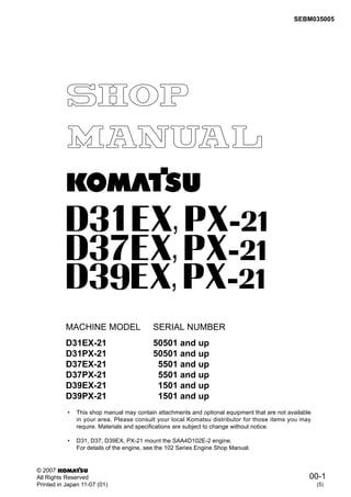
  • 1. 00-1 SEBM035005 © 2007 All Rights Reserved Printed in Japan 11-07 (01) (5) MACHINE MODEL SERIAL NUMBER D31EX-21 50501 and up D31PX-21 50501 and up D37EX-21 5501 and up D37PX-21 5501 and up D39EX-21 1501 and up D39PX-21 1501 and up • This shop manual may contain attachments and optional equipment that are not available in your area. Please consult your local Komatsu distributor for those items you may require. Materials and specifications are subject to change without notice. • D31, D37, D39EX, PX-21 mount the SAA4D102E-2 engine. For details of the engine, see the 102 Series Engine Shop Manual.
  • 2. 00-2 D31/37/39EX, PX-21 GENERAL (1) CONTENTS No. of page 01 GENERAL ................................................................................................................................ 01-1 10 STRUCTURE AND FUNCTION, MAINTENANCE STANDARD..................................................... 10-1 20 TESTING AND ADJUSTING................................................................................... 20-1 30 DISASSEMBLY AND ASSEMBLY ................................................................... 30-1 90 OTHERS..................................................................................................................................... 90-1
  • 3. D31/37/39EX, PX-21 30-9 DISASSEMBLY AND ASSEMBLY FUEL INJECTION PUMP (1) REMOVAL AND INSTALLATION OF FUEL INJECTION PUMP ASSEMBLY SPECIAL TOOLS REMOVAL 1. Open up both engine hoods (1). 2. Remove left engine side cover (2). 3. Close the fuel stop valve. 4. Disconnect fuel control linkage (3). [*1] 5. Disconnect decelerator pedal linkage (4). [*2] 6. Remove engine stop solenoid (5). [*3] 7. Disconnect air tube (6). 8. Disconnect fuel inlet hoses (7) and (8) and return hose (9). 9. Remove fuel tubes (10) and (11). 10. Remove lubrication tube (12). 11. Disconnect 4 fuel injection tubes (13). a Disconnect the tube end on the fuel injection pump side. Symbol Part No. Part Name Necessity Q'ty New/remodel Sketch A 1 795-799-1131 Gear t 1 2 795-799-1390 Remover t 1
  • 4. 30-10 D31/37/39EX, PX-21 DISASSEMBLY AND ASSEMBLY FUEL INJECTION PUMP (1) 12. Using tool A1, rotate the crankshaft forward to match the timing gear to the fuel injection timing. a See TESTING AND ADJUSTING, Testing and adjusting fuel injection timing. 13. Remove cap (14). [*4] a Remove with a filter wrench, etc. 14. Remove injection pump nut (15). [*5] a Take care not to drop the nut in the case. 15. Using tool A2, disconnect the shaft and drive gear of the fuel injection pump. 16. Remove brackets (16) and (17). 17. Remove 4 mounting bolts (18) and fuel injection pump assembly (19). INSTALLATION • Carry out installation in the reverse order to removal. [*1] [*2] a Adjust the fuel control linkage and decelera- tor pedal linkage. For details, see TESTING AND ADJUSTING, Adjusting fuel control le- ver linkage and decelerator pedal linkage. [*3] a Adjust the engine stop solenoid linkage. For details, see TESTING AND ADJUSTING, Adjusting engine stop solenoid linkage. [*4] a Tighten the cap by turning it by 180 degrees. [*5] a Install the fuel injection pump assembly ac- cording to the following procedure. 1) Using tool A1, crank the engine forward slowly and push No. 1 cylinder compression top dead center positioning pin (20) into the gear.
  • 5. D31/37/39EX, PX-21 30-11 DISASSEMBLY AND ASSEMBLY FUEL INJECTION PUMP (1) a Referring to the following, push positioning pin (20) into the gear securely. • Dimension "a" of pin in free state: 24 mm • Dimension "b" of pin when it is in contact with gear: 20 mm • Dimension "c" of pin when it is pushed into gear: 16 mm a Stop barring immediately after the position- ing pin is pushed in (to prevent the position- ing pin from being broken). 2) Remove plug (21) and timing pin (22). 3) Reverse the fitting position of timing pin (22) and match the groove of the timing pin to pointer (23) in the pump and tighten plug (21) temporarily. a If the tooth of pointer (23) is not matched to the hole of the timing pin, match it by turning the fuel injection pump shaft. 4) Install fuel injection pump assembly (19) and tighten nut (18). 3 Nut: 43 ± 6 Nm {4.38 ± 0.61 kgm} 5) Tighten fuel injection pump nut (15). a When installing the nut, take care ex- tremely not to drop it in the case. 3 Nut: 12.5 ± 2.5 Nm {1.27 ± 0.25 kgm} a This value is not the final torque. a Do not heighten the tightening torque of the nut more than above value so that the No. 1 cylinder compression top dead center positioning pin will not be dam- aged. 6) Disengage No. 1 cylinder compression top dead center positioning pin (20).
  • 6. 30-12 D31/37/39EX, PX-21 DISASSEMBLY AND ASSEMBLY FUEL INJECTION PUMP (1) 7) Remove plug (21) and install timing pin (22) in the reversed fitting position, then install the plug to the fuel injection pump. 3 Plug: 14.7 Nm {1.5 kgm} 8) Tighten fuel injection pump nut (15) securely. 3 Nut: 95 ± 10 Nm {9.7 ± 1.02 kgm} • After the above work, carry out installation in the reverse order to removal. a Adjust the fuel injection timing. For details, see TESTING AND ADJUSTING, Adjusting fuel in- jection timing. • Bleeding air Bleed air from the fuel circuit. For details, see TESTING AND ADJUSTING, Bleeding air from fuel circuit.
  • 7. D31/37/39EX, PX-21 30-13 DISASSEMBLY AND ASSEMBLY CYLINDER HEAD (1) REMOVAL AND INSTALLATION OF CYLINDER HEAD ASSEMBLY SPECIAL TOOLS REMOVAL k Disconnect the cable from the negative (–) ter- minal of the battery. k If the water temperature in the radiator is high, you may get scalded. Accordingly, wait until the water temperature lowers, then drain. 1. Remove the mounting bolts and cover (1). 2. Loosen the radiator cap and drain the cooling water. 6 Radiator: Approx. 20 llll 3. Close the fuel stop valve. 4. Remove clip of heater hose (2) and disconnect dust indicator hose (3). a Disconnect the dust indicator hose end on the air cleaner side. 5. Using eyebolts, lift off engine hood (4). 4 Engine hood: 45 kg 6. Remove both engine covers (5). Symbol Part No. Part Name Necessity Q'ty New/remodel Sketch A 3 795-799-1170 Puller q 1 4 790-331-1110 Wrench t 1
  • 8. 30-14 D31/37/39EX, PX-21 DISASSEMBLY AND ASSEMBLY CYLINDER HEAD (1) 7. Disconnect charge air cooler hose (6). [*1] 8. Disconnect air cleaner hose (7). [*2] 9. Remove air cleaner band (8). [*3] 10. Disconnect the 3 wiring connectors, then dis- connect the wiring harness clamp. • (9): (CN1) • (10): (CN2) • (11): (CN3) 11. Remove the mounting bolt and air cleaner assembly (12). [*4] 12. Disconnect 3 wiring connectors (13) and remove the heater relay. [*5] • Secured with bolt (CNT5) • Secured with nut (CNT6), (CNT12) 13. Disconnect compressor wiring connector (CN23) (14). 14. Disconnect engine stop solenoid wiring har- nesses (CNT17) and (CNT18) (15). 15. Disconnect wiring harness clamp (16). 16. Disconnect engine water temperature sensor connector (CN20) (17). 17. Disconnect 2 alternator wiring harnesses. [*6] • (18): (CNT15) • (19): (CNT16)
  • 9. D31/37/39EX, PX-21 30-15 DISASSEMBLY AND ASSEMBLY CYLINDER HEAD (1) 18. Disconnect charge air cooler hose (20). [*7] 19. Disconnect oil filler tube (21) and oil filler hose (22). 20. Disconnect harness clamp (23). 21. Remove muffler clamp (24). [*8] 22. Remove the mounting bolts and lift off muffler assembly (25). a Remove the 4 upper and 2 lower muffler mounting bolts. 4 Muffler assembly: 40 kg (Including bracket) 23. Remove reservoir tank (26). [*9] 24. Disconnect radiator hose (27). [*10] 25. Disconnect heater hose (28). 26. Remove compressor bracket (29). 27. Remove fan guard (30). a Remove only the right fan guard. 28. Remove fan belt (31). [*11] a Using a wrench, etc., remove the fan belt from the tension pulley. 29. Remove 2 mounting bolts (32) and alternator assembly (33). 30. Remove the brackets and clamps from 2 places and disconnect 4 fuel tubes (34). [*12] a Disconnect the fuel tubes in order from the No. 1 tube (on the fan side). 31. Disconnect the linkage of engine stop solenoid (35) and remove the engine stop solenoid. [*13] 32. Remove the clamp and 2 delivery tubes (36). [*14] 33. Remove the mounting bolt and bracket (37). [*15] a Remover the bracket and the fuel filter to- gether. 34. Remove air tube (38). 35. Remove bracket (39) and spill tube (40). 36. Disconnect boost hose (41) and remove clamp (42). a Disconnect boost hose end on the intake side.
  • 10. 30-16 D31/37/39EX, PX-21 DISASSEMBLY AND ASSEMBLY CYLINDER HEAD (1) 37. Remove water drain tube (43). a Remove the 2 mounting bolts, and the tube is removed and divided into 2 pieces. 38. Disconnect charge air cooler hose (44). [*16] 39. Disconnect turbocharger lubrication inlet tube (45) and outlet tube (46). [*17] a Disconnect end of tube (45) on the oil filter side. 40. Remove bracket (47) and cover (48). 41. Remove turbocharger assembly (49) and exhaust manifold (50). [*18] 42. Remove 4 head covers (51). [*19] 43. Remove the intake air heater ground wire, con- nector (52), intake air heater (53), and cover (54). [*20] 44. Remove 4 nozzle holder assemblies (55). a If the nozzle holder is difficult to remove, use tool A3. a Take care that dirt and foreign matter will not enter the mounting part of the nozzle holder.
  • 11. D31/37/39EX, PX-21 30-17 DISASSEMBLY AND ASSEMBLY CYLINDER HEAD (1) 45. Remove rocker arm assembly (56). [*21] a Loosen the locknut, then loosen the adjust- ment screw by 2 – 3 turns. 46. Remove push rod (57). 47. Lift off cylinder head assembly (58). 4 Cylinder head assembly: 40 kg 48. Remove cylinder head gasket (59). INSTALLATION • Carry out installation in the reverse order to removal. [*1] a When connecting the hose, apply spray grease to the mating part (tube). 3 Charge air cooler hose clamp: 5.9 ± 0.5 Nm {0.6 ± 0.05 kgm} [*2] 3 Air cleaner hose clamp: 5.9 ± 0.5 Nm {0.6 ± 0.05 kgm} [*3] 3 Band: 9.8 ± 1.0 Nm {1.0 ± 0.1 kgm} [*4] a Install the air cleaner cover with the top mark up. [*5] 3 Bolt: 1.86 – 2.45 Nm {0.19 – 0.25 kgm} 3 Nut: 2.45 – 2.94 Nm {0.25 – 0.3 kgm} [*6] 3 Nut: 23.5 – 29.4 Nm {2.4 – 3 kgm} [*7] a When connecting the hose, apply spray grease to the mating part (tube). 3 Charge air cooler hose clamp: 5.9 ± 0.5 Nm {0.6 ± 0.05 kgm} [*8] a Use a new clamp. 3 Clamp: 8.8 ± 0.5 Nm {0.9 ± 0.05 kgm} [*9] a Pass the reservoir tank drain hose through the guide pipe of the shroud. [*10] 3 Radiator hose clamp: 8.8 ± 0.5 Nm {0.9 ± 0.05 kgm} [*11] 3 Tension pulley bolt: 43 ± 6 Nm {4.38 ± 0.61 kgm} [*12] 3 Bracket mounting bolt: 24 ± 4 Nm {2.45 ± 0.41 kgm} [*13] a Adjust the engine stop solenoid linkage. For details, see TESTING AND ADJUSTING, Adjusting engine stop solenoid linkage.
  • 12. 30-18 D31/37/39EX, PX-21 DISASSEMBLY AND ASSEMBLY CYLINDER HEAD (1) [*14] 3 Bracket mounting bolt: 24 ± 4 Nm {2.45 ± 0.41 kgm} [*15] 3 Bracket mounting bolt: 24 ± 4 Nm {2.45 ± 0.41 kgm} [*16] a When connecting the hose, apply spray grease to the mating part (tube). 3 Charge air cooler hose clamp: 5.9 ± 0.5 Nm {0.6 ± 0.05 kgm} [*17] 3 Nipple: 34 ± 5 Nm {3.5 ± 0.5 kgm} 3 Bolt: 10 ± 2 Nm {1.0 ± 2.0 kgm} [*18] 3 Nut: 29.4 – 44.2 Nm {3 – 4.5 kgm} [*19] 3 Bolt: 24 ± 4 Nm {2.45 ± 0.41 kgm} [*20] a Secure clearance of at least 10 mm between the ground wire and fuel tube. [*21] • Install the rocker arm assembly and cylinder head assembly according to the following procedure. a Check that there is not dirt or foreign matter on the mating face of the cylinder head and in the cylinders. 1) Set cylinder head gasket (59) to the cylinder block. a Check that the gasket is matched to the holes of the block. 2) Sling cylinder head assembly (58) and set it to the cylinder block. 3) Install push rod (57). 4) Install rocker arm assembly (56) and tighten the bolt with your fingers. a Check that the adjustment screw ball is fitted to the socket of the push rod. 5) Tighten the cylinder head mounting bolts in the order shown in the following figure. 2 Apply engine oil (SAE15W-40) to the threads and seats of the mounting bolts. 3 Cylinder head mounting bolt: 1st time: Tighten to 90 ± 5 Nm {9.18 ± 0.51 kgm} in the order of [1] – [18]. 2nd time: Tighten to 120 ± 5 Nm {12.24 ± 0.51 kgm} in the order of [3], [6], [11], and [14]. 3rd time: i) When using tool A4 • Tighten bolts by 90 ± 5° in the order of [1] – [18] with an angle tightening wrench (Tool A4). ii) When not using tool A4 • Make marks on the bolts and head with a marker pen, then tighten each bolt by 90 ± 5°.
  • 13. D31/37/39EX, PX-21 30-19 DISASSEMBLY AND ASSEMBLY CYLINDER HEAD (1) 6) Tighten rocker arm assembly (56). 3 Rocker arm mounting bolt: 24 ± 4 Nm {2.45 ± 0.41 kgm} a Adjust the valve clearance. For details, see TESTING AND ADJUSTING, Adjusting valve clearance. • Refilling with water a Add water through the water filler to the specified level. Run the engine until the wa- ter is heated, then check the water level again. • Bleeding air a Bleed air from the fuel circuit. For details, see TESTING AND ADJUSTING, Bleeding air from fuel circuit.
  • 14. 30-20 D31/37/39EX, PX-21 DISASSEMBLY AND ASSEMBLY ENGINE FRONT SEAL (1) REMOVAL AND INSTALLATION OF ENGINE FRONT SEAL SPECIAL TOOLS REMOVAL k Disconnect the cable from the negative (–) ter- minal of the battery. 1. Remove the radiator guard assembly. For details, see REMOVAL OF RADIATOR GUARD ASSEMBLY. 2. Remove 4 mounting bolts and fan (1). 3. Using lever [1], remove fan belt (2). k Take care not catch your fingers between the tensioner and fan pulley. 4. Remove fan pulley (3). 5. Remove 4 mounting bolts (4) and crankshaft pulley/vibration damper (5). [*1] 6. Remove 27 mounting bolts (6) and cover (7). [*2] 7. Remove dust seal (8). 8. Remove seal (9). [*3] Symbol Part No. Part Name Necessity Q'ty New/remodel Sketch B 1 795-799-2610 Installer t 1 2 795-799-2620 Installer t 1
  • 15. D31/37/39EX, PX-21 30-21 DISASSEMBLY AND ASSEMBLY ENGINE FRONT SEAL (1) INSTALLATION • Carry out installation in the reverse order to removal. [*1] 3 Mounting bolt of crankshaft pulley/ vibration damper: 125 ± 5 Nm {12.75 ± 0.51 kgm} a Install the crankshaft pulley/vibration damper lightly, then install the fan belt and tighten the mounting bolts to the specified torque. [*2] a Install the front cover according to the follow- ing procedure. 1) Apply ThreeBond 1207D or equivalent in the form of a string 1 – 2 mm thick to the gasket fitting face of the front cover. a Limit the projection of the gasket from the oil pan fitting face to 0.25 mm. 2) Install the gasket to the front cover, and then install them to the engine. 3) Tighten the 7 mounting bolts in the fol- lowing order. 3 Mounting bolt: 24 ± 4 Nm {2.45 ± 0.41 kgm} 4) Tighten the 20 mounting bolts in the fol- lowing order. 3 Mounting bolt: 24 ± 4 Nm {2.45 ± 0.41 kgm}
  • 16. 30-22 D31/37/39EX, PX-21 DISASSEMBLY AND ASSEMBLY ENGINE FRONT SEAL (1) [*3] a Install the dust seal to the crankshaft accord- ing to the following procedure. a Even if a dust seal has not been installed, in- stall the dust seal contained in the front seal kit. 1) Install dust seal (8) to the end of the crankshaft. 2) Using tool B2, press fit dust seal (8). a Press fit the dust seal until the inside end of tool B2 touches the end of the crankshaft. [*4] a Install the engine front seal to the front cover according to the following procedure. 1) Set engine front seal (7) to tool B1. a Since plastic part [2] on the inside of the engine front seal is used to guide the front cover to the crankshaft, do not re- move it from the engine front seal. 2) Press fit engine front seal (7) to front cover (6). a Press fit the engine front seal until the shoulder of tool B1 touches the inside end of the front cover.
  • 17. D31/37/39EX, PX-21 30-23 DISASSEMBLY AND ASSEMBLY ENGINE REAR SEAL (1) REMOVAL AND INSTALLATION OF ENGINE REAR SEAL SPECIAL TOOLS REMOVAL 1. Remove the coupling. For details, see REMOVAL AND INSTALLATION OF DAMPER. 2. Remove the mounting bolts, set guide bolts [1], and lift off flywheel assembly (1). [*1] 4 Flywheel assembly: 35 kg 3. Remove engine rear seal (2). [*2] a Method of removing with seal puller 1) Make a hole about 3 mm in diameter on the seal carrier with a drill. 2) Screw the tip of seal puller C into the drilled hole and slide the hammer to remove engine rear seal (2). a Method of removing with screwdriver • Break the seal carrier of engine rear seal (2) with a screwdriver to remove the en- gine rear seal. a Take care not to damage the seal fitting part of the flywheel housing and the seal contact surface of the crankshaft. Symbol Part No. Part Name Necessity Q'ty New/remodel Sketch C 795-931-1100 Seal puller q 1
  • 18. Thank you very much for your reading. Please Click Here. Then Get COMPLETE MANUAL. NO WAITING NOTE: If there is no response to click on the link above, please download the PDF document first and then click on it.
  • 19. 30-24 D31/37/39EX, PX-21 DISASSEMBLY AND ASSEMBLY ENGINE REAR SEAL (1) INSTALLATION • Carry out installation in the reverse order to removal. [*1] a Tighten the mounting bolts in the order show below. 3 Flywheel mounting bolt: 137 ± 7 Nm {13.97 ± 0.71 kgm} [*2] a Install the engine rear seal according to the following procedure. 1) Insert pilot [2] in new seal (3). a Before inserting the pilot, clean, de- grease, and dry the lip surface of the seal. 2) Insert seal (3) and pilot [2] together in the crankshaft and push the seal carrier into the flywheel housing. a Before inserting the seal, clean, de- grease, and dry the seal contact surface of the crankshaft. 3) Pull out pilot [2] and push in seal (3) further. 4) Using aligning tool [3], insert the seal to the proper depth. a Lightly hit the top, bottom, right, and left of the aligning tool with a hammer to push in the seal, taking care that the seal carrier will not be bent.
  • 20. D31/37/39EX, PX-21 30-25 DISASSEMBLY AND ASSEMBLY RADIATOR GUARD (1) REMOVAL AND INSTALLATION OF RADIATOR GUARD ASSEMBLY REMOVAL k Disconnect the cable from the negative (–) ter- minal of the battery. k Lower the work equipment to the ground and stop the engine. Then, loosen the hydraulic oil filler cap slowly to release the internal pressure of the hydraulic tank. k If the water temperature in the radiator is high, you may get scalded. Accordingly, wait until the water temperature lowers, then drain. 1. Remove the mounting bolts and cover (1). 2. Loosen the radiator cap and drain the cooling water. 6 Radiator: Approx. 15 llll 3. Remove clip of heater hose (2) and disconnect dust indicator hose (3). a Disconnect the dust indicator hose end on the air cleaner side. 4. Using eyebolts, lift off engine hood (4). 4 Engine hood: 80 kg 5. Remove both engine covers (5). 6. Remove reservoir tank bracket (6) and discon- nect reservoir tank hose (7). [*1] 7. Disconnect charge air cooler outlet hose (8). 8. Disconnect radiator inlet hose (9). 9. Disconnect horn wiring connector (CN22) (10). 10. Remove both fan guards (11).
  • 21. 30-26 D31/37/39EX, PX-21 DISASSEMBLY AND ASSEMBLY RADIATOR GUARD (1) 11. Disconnect oil cooler outlet hose (12). a Prepare a blind plug before disconnecting the hose. 12. Disconnect radiator outlet hose (13). 13. Disconnect charge air cooler inlet hose (14). 14. Disconnect oil cooler inlet hose (15). a Prepare a blind plug before disconnecting the hose. 15. Sling radiator guard assembly (17) temporarily and remove 8 mounting bolts (16) from both sides and 2 from the underside. [*2] 16. Lift off radiator guard assembly (17). 4 Radiator guard assembly: 370 kg