
Recommended
Recommended
More Related Content
More from wedsrffcdgdv
More from wedsrffcdgdv (20)
Recently uploaded
Recently uploaded (20)
Komatsu 12 v170 1 diesel engine service repair manual
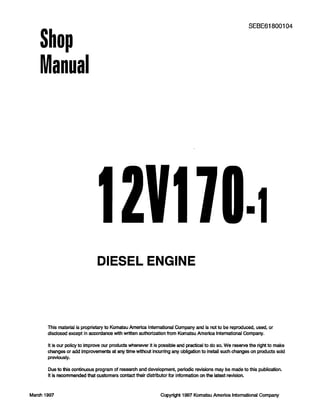
- 1. Shop Manual SEBE61800104 12v17DIESEL ENGINE This material is proprietary to Komatsu America International Company and is not to be reproduced, used, or disclosed except in accordance with written authorization from Komatsu America lntemational Company. It is our policy to improve our products whenever it is possible and practical to do so. We reserve the right to make changes or add lmprovements at any time without Incurring any obligation to install such changes on products sold previously. Due to this continuous program of research and development, periodic revisions may be made to this publication. It is recommended that customers contact their distributor for information on the latest revision. March 1997 Copyright 1997 Komatsu America International Company
- 2. CONTENTS No. of page 01 GENERAL ............................................................................................................01-1 11 STRUCTURE AND FUNCTION ........................................................... II-I 12 TESTING AND ADJUSTING ................................................................ 12-1 13 DISASSEMBLY AND ASSEMBLY .................................................... 13-1 14 MAINTENANCE STANDARD ............................................................... 14-1 Q z 15 REPAIR AND REPLACEMENT OF PARTS .................................. 15-1 00-2 0
- 3. SAFETY SAFETY NOTKZE SAFETY SAFETY NOTICE IMPORTANT SAFETY NOTICE Proper service and repair is extremely important for safe machine operation. The service and repair techniques recommended by Komatsu and described in this manual are both effective and safe. Some of these techniques require the use of tools specially designed by Komatsu for the specific purpose. To prevent injury to workers, the symbol A is used to mark safety precautions in this manual. The cautions accompanying these symbols should always be followed care- fully. If any dangerous situation arises or may possibly arise, first consider safety, and take the necessary actions to deal with the situation. GENERAL PRECAUTIONS Mistakes in operation are extremely dangerous. Read the Operation and Maintenance Manual carefully BEFORE operating the machine. 1. Before carrying out any greasing or repairs, read all the precautions given on the decals which are fixed to the machine. 2. When carrying out any operation, always wear safety shoes and helmet. Do not wear loose work clothes, or clothes with buttons missing. . Always wear safety glasses when hitting parts with a hammer. . Always wear safety glasses when grind- ing parts with a grinder, etc. 3. If welding repairs are needed, always have a trained, experienced welder carry out the work. When carrying out welding work, al- ways wear welding gloves, apron, hand shield, cap and other clothes suited for weld- ing work. When carrying out any operation with two or more workers, always agree on the oper- ating procedure before starting. Always in- form your fellow workers before starting any step of the operation. Before starting work, hang UNDER REPAIR signs on the controls in the operator’s compartment. Keep all tools in good condition and learn the correct way to use them. 6. Decide a place in the repair workshop to keep tools and removed parts. Always keep the tools and parts in their correct places. Always keep the work area clean and make sure that there is no dirt or oil on the floor. Smoke only in the areas provided for smok- ing. Never smoke while working. 7. Before adding oil or making any repairs, park the machine on hard, level ground, and block the wheels or tracks to prevent the machine from moving. 8. Before starting work, lower blade, ripper, bucket or any other work equipment to the ground. If this is not possible, insert the safety pin or use blocks to prevent the work equipment from falling. In addition, be sure to lock all the control levers and hang warn- ing signs on them. PREPARATIONS FOR WORK 9. When disassembling or assembling, support the machine with blocks, jacks or stands before starting work. IO. Remove all mud and oil from the steps or other places used to get on and off the ma- chine. Always use the handrails, ladders or steps when getting on or off the machine. Never jump on or off the machine. If it is impossible to use the handrails, ladders or steps, use a stand to provide safe footing. 00-3
- 4. SAFETY SAFETY NOTICE PRECAUTIONS DURING WORK 11. 12. 13. When removing the oil filler cap, drain plug or hydraulic pressure measuring plugs, loosen them slowly to prevent the oil from spurting out. Before disconnecting or removing compo- nents of the oil, water or air circuits, first remove the pressure completely from the circuit. The water and oil in the circuits are hot when the engine is stopped, so be careful not to get burned. Wait for the oil and water to cool before carrying out any work on the oil or water circuits. Before starting work, remove the leads from the battery. Always remove the lead from the negative (-1 terminal first. 14. When raising heavy components, use a hoist or crane. Check that the wire rope, chains and hooks are free from damage. Always use lifting equipment which has ample capacity. Install the lifting equipment at the correct places. Use a hoist or crane and operate slowly to prevent the component from hit- ting any other .part. Do not work with any part still raised by the hoist or crane. 15. When removing covers which are under in- ternal pressure or under pressure from a spring, always leave two bolts in position on opposite sides. Slowly release the pres- sure, then slowly loosen the bolts to remove. 16. When removing components, be careful not to break or damage the wiring. Damaged wiring may cause electrical fires. 17. When removing piping, stop the fuel or oil from spilling out. If any fuel or oil drips onto the floor, wipe it up immediately. Fuel or oil on the floor can cause you to slip, or can even start fires. 18. As a general rule, do not use gasoline to wash parts. In particular, use only the mini- mum of gasoline when washing electrical parts. 19. Be sure to assemble all parts again in their original places. Replace any damaged parts with new parts. . When installing hoses and wires, be sure that they will not be damaged by contact with other parts when the machine is be- ing operated. 20. When installing high pressure hoses, make sure that they are not twisted. Damaged tubes are dangerous, so be extremely care- ful when installing tubes for high pressure circuits. Also, check that connecting parts are correctly installed. 21. When assembling or installing parts, always use the specified tightening torques. When installing protective parts such as guards, or parts which vibrate violently or rotate at high speed, be particularly careful to check that they are installed correctly. 22. When aligning two holes, never insert your fingers or hand. Be careful not to get your fingers caught in a hole. 23. When measuring hydraulic pressure, check that the measuring tool is correctly assem- bled before taking any measurements. 24. Take care when removing or installing the tracks of track-type machines. When removing the track, the track sepa- rates suddenly, so never let anyone stand at either end of the track. 00-4
- 5. FOREWORD GENERAL FOREWORD GENERAL This shop manual has been prepared as an aid to improve the quality of repairs by giving the serviceman an accurate understanding of the product and by showing him the correct way to perform repairs and make judgements. Make sure you understand the contents of this manual and use it to full effect at every opportunity. This shop manual mainly contains the necessary technical information for operations performed in a service workshop. For ease of understanding, the manual is divided into the following chapters; these chapters are further divided into the each main group of components. STRUCTURE AND FUNCTION This section explains the structure and function of each component. It serves not only to give an understanding of the structure, but also serves as reference material for troubleshooting. TESTING AND ADJUSTING This section explains checks to be made before and after performing repairs, as well as adjustments to be made at completion of the checks and repairs. Troubleshooting charts correlating “Problems” to “Causes” are also included in this section. DISASSEMBLY AND ASSEMBLY This section explains the order to be followed when removing, installing, disassembling or assembling each component, as well as precautions to be taken for these operations. MAINTENANCE STANDARD This section gives the judgement standards when inspecting disassembled parts. NOTICE The specifications contained in this shop manual are subject to change at any time and without any advance notice. Use the specifications given in the book with the latest date. 00-5
- 6. FOREWORD HOW TO READ THE SHOP MANUAL HOW TO READ THE SHOP MANUAL VOLUMES REVISED EDITION MARK Shop manuals are issued as a guide to carrying out repairs. They are divided as follows: Chassis volume: Issued for every machine model Engine volume: Issued for each engine series Electrical volume: Attachments volume: I Each issued as one volume to cover all models When a manual is revised, an edition mark (@@@....I is recorded on the bottom of the pages. REVISIONS These various volumes are designed to avoid duplicating the same information. Therefore, to deal with all repairs for any model , it is neces- sary that chassis, engine, electrical and attach- ment volumes be available. Revised pages are shown in the LIST OF RE- VISED PAGES next to the CONTENTS page. SYMBOLS DISTRIBUTION AND UPDATlNG Any additions, amendments or other changes will be sent to KOMATSU distributors. Get the most up-to-date information before you start any work. FILING METHOD 1. See the page number on the bottom of the page. File the pages in correct order. 2. Following examples show how to read the page number. Example 1 (Chassis volume): 10 -3 Item number (IO. Structure and Function) Consecutive page number for each item. Example 2 (Engine volume): Unit number (I. Engine) Item number (2. Testing and Adjusting) Consecutive page number for each item. 3. Additional pages: Additional pages are indi- cated by a hyphen (-1 and number after the page number. File as in the example. Example: 10-4 12-203 So that the shop manual can be of ample prac- tical use, important safety and quality portions are marked with the following symbols. Symbol a * &Ikg %b 4 Item Safety Caution Weight ighteninc torque Coat Xl, water Drain Remarks Special safety precautions are necessary when performing the work. Special technical precautions or other precautions for pre- serving standards are neces- sary when performing the work. Weight of parts of systems. Caution necessan/ when se- lecting hoisting wire, or when working posture is important, etc. Places that require special at- tention for the tightening torque during assembly. Places to be coated with ad- hesives and lubricants, etc. Places where oil, water or fuel must be added, and the ca- pacity. Places where oil or water must be drained, and quan- tity to be drained. 10-4-I - 1O-4-2 k Added pages -~~~~f~~I~ 10-5 12-204 00-6
- 7. 01 GENERAL Specifications ............................................... Ol- 2 Engine performance curve .......................... Ol- 4 Weight table .................................................. 01-16 01-l 0
- 8. GENERAL SPECIFICATIONS SPECIFICATIONS Engine model SA12V170-1 Applicable machine Number of cylinders - Bore x Stroke Total piston displacement Firing order - F .2 2 i.- n Overall length Overall width Overall height (excluding exhaust pipe) Overall height (including exhaust pipe) Flywheel horsepower Maximum torque High idling speed Low idling speed Minimum fuel consumption ratio Dry weight Fuel pump Lubricating oil amount (refill capacity) Coolant amount Alternator 24V, 75A Starting motor Battery mm e ICC) D575A-2 D575A-2 Engine serial No. Engine serial No. 10024-10096 10097 and up 12-170x170 46.3 (46,300) Rl-L6-R5-L2-R3-L4-R6-Ll-R2-L5-R4-L3 mm 2,766 2,766 mm 1,720 1,720 mm 2,805 2,805 mm - - kW/rpm {HP/rpmI kW/rpm {kgm/rpmI rpm rpm g/kW l h {g/HP l h} Turbocharger Air compressor Others 784/l ,800 11.O~~rY&8001 5,000/1,300 {51~(;;001 1,950 - 2,050 600 - 700 215 11601 6,210 BOSCH PE-ZWX type BOSCH RSUV centrifugal, allspeed type 137 (127) 24V, llkWx2 12V200Ah x 4 KOMATSU KTR130 x 2 (water cooled type) With after cooler With after cooler 78411,800 {1,0~~~$300~ 5,000/1,300 {51~0$$00~ 1,950 - 2,050 600 - 700 215 11601 6,210 BOSCH PES-P(PS7S) type BOSCH RSUV centrifugal, allspeed type 137 (127) 298 24V, 75A 24V, llkWx2 12V200Ah x 4 KOMATSU KTRISO x 2 (water cooled type) - 01-2 0
- 9. GENERAL SPECIFICATIONS SA12V170-1 D575A-2SD (Super Dozer) HD1200-1 HD1200M-1 12-170x170 46.3 {46,300} Rl-L6-R5-L2-R3-L4-R6-Ll-R2-L5-R4-L3 2,766 1,720 2,805 - 858/I ,800 ~1.150/1.800~ z 5,660/l ,300 % {57;~;;001 z 1,950 - 2,050 600 - 700 215 {I601 6,650 5,350 5,280 BOSCH PE-P(PS7S) type BOSCH PES-ZWX type BOSCH RSUV centrifugal, allspeed type BOSCH RSUV centrifugal, allspeed type 137 (127) 131 (106) 121 (106) 298 280 I 480 24V. 75A 24V, IlkWx 2 12V200Ah x 4 KOMATSU KTR130 x 2 (water cooled type) With after cooler 2,346 1,704 1,839 2,346 1,657 1,793 - - 960/2,100 87812,100 {I ,2w~;oo~ ~l,l~~Q2~;00~ 5,190/1,400 4,640/l ,400 {53~cv&OOI {47;~$001 2,300 - 2,400 2,300 - 2,400 600 - 700 600 - 700 211 209 11571 I1561 24V, 75A 24V, 75A Air starter 37.5 kW Air starter 37.5 kW 12V200Ah x 4 12V200Ah x 4 KOMATSU KTR130 x 2 ZEXEL recipro caution single cylinder x 2 With after cooler KOMATSU KTR130 x 2 ZEXEL recipro caution single cylinder x 2 With after cooler 01-3 0
- 10. GENERAL SPECIFICATIONS IEngine model SA12V170-1 Applicable machine EGI 100-l Generator Number of cylinders - Bore x Stroke Total piston displacement Firing order mm e {cc) 12-170x170 46.3 {46,300} Rl-L6-R5-L2-R3-L4-R6-Ll-R2-L5-R4-L3 Overall length Overall width Overall height (excluding exhaust pipe) Overall height (including exhaust pipe) mm mm mm mm 2,697 1,500 2,000 2,340 1,420 1,977 - - Flywheel horsepower kW/rpm IHP/rpmI 874/l ,500 (50Hz) {I .170/l ,500) (50Hz) Maximum horsepower kW/rpm 0-fP/rpmI 862/1,500 (50Hz) {1,160/1,500~ (50H.z) 950/1,800 (60Hz) {1,27O/I(;C$ (6OHz) 950/l ,500 (50Hz) ~1,270/1,500~ (50Hz)I 1,040/l ,800 (60Hz) {1,390/1(8~~)I (60Hz) 860/l ,800 i6bHz) {1,29o’:iu8~~; (60Hz) - High idling speed rpm Max.1.560 (at rated, 50Hz jax.1,580 (at maximum, 50 Max.1,870 (at rated, 60Hz rlax.1,890 (at maximum, 601 Max. 1,560 (50Hz) Max. 1,890 (60Hz) Low idlingn speed Fuel consumption ratio rpm 900 - 1,000 700 - 900 g/kW l h 216 (at rated) 216 (at rated) {g/HP l W (161) (at rated) {I611 (at rated) Dry weight kg 5,600 5,450 Fuel pump BOSCH PE-ZWX type Governor BOSCH RSUV centrifugal, allspeed type Lubricating oil amount (refill capacity) e Coolant amount e Alternator Starting motor Battery 24V, 35A 24V, 35A 24V, llkWx2 24V, IlkWx2 12V200Ah x 4 12V200Ah x 4 !Turbocharger Air compressor Others KOMATSU KTR150 x 2 KOMATSU KTR150 x 2 - I - With after cooler I With after cooler 01-3-l 0 * : optional parts
- 12. GENERAL ENGINE PERFORMANCE CURVE ENGINE PERFORMANCE CURVE SA12V170-1 (FOR D575A-2) Flywheel horsepower: 783 KW (1,050 HP)/1,800 rpm Maximum torque: 5,001 Nm (510 kgm)/1,300 rpm I - , - z ‘z 1300 1200 1100 1000 900 600 700 600 / 500 I 400 300 I 200 I 100 - I 0 600 600 1000 1200 1400 1600 I600 2000 2200 2400 Eneine speed (rpm) SAE00237 01-4 0
- 13. GENERAL ENGINE PERFORMANCE CURVE SA12V170-1 (FOR D575A-2SD) Flywheel horsepower: 858 KW (1,150 HP)/1,800 rpm Maximum torque: 5,658 Nm (577 kgm)/1,300 rpm ;; 1100 i2 z 1000 900 a00 s 700 2 600 4oc 3OC 2OC lO( c 600 500 400 300 200 ;j 5 100 1300 0 1200 1100 1000 900 1 I I 600 700 600 500 I / 400 300 I, 200 I 100 I 0 600 600 1000 1200 1400 1600 I600 2000 2200 2400 Engine speed (rpm) I 6000 5000 4000 ,” - 3000 E : - 2000 - 1000 -0 SAE00236 01-5 0
- 14. GENERAL ENGINE PERFORMANCE CURVE SAlPV170-1 (FOR HD1200-1) Flywheel horsepower: 962 KW (1,290 HP)/2,100 rpm Maximum torque: 5,197 Nm (530 kgm)/1,400 rpm 1300 - 1000 - 1300 1200 - 900 - 1200 1100 - II00 600 - 1000 - 1000 900 - ‘0° 900 600 - 600 - 800 2 700 - 700 s 500 - 600 - 600 400 - 500 - 500 400 - 300 - 400 300 - 300 200 - 200 - 200 100 - 100 - 100 o- o- 0 600 600 1000 1200 1400 1600 1600 2000 2200 2400 Engine speed (rpm) 600 6000 500 I 5000 400 4000 t 2 300 3000 : F 200 - 2000 100 - 1000 0 -0 SAE00239 01-6 0
- 15. GENERAL ENGINE PERFORMANCE CURVE SA12V170-1 (FOR HD1200M-1) Flywheel horsepower: 878 KW (1,177 HP)/2,100 rpm Maximum torque: 4,638 Nm (473 kgm)/1,400 rpm z ‘j; z 5 Y s 1300- IOOO- 1300 1200 - 900 - 1200 1100 - 1100 600 - 1000 - 1000 900 - ‘0° 900 600 - 600 - 600 D 2 700 - 700 s 500 - 600 - 600 400 - 500 - 500 400 - 300 - 400 300 - 300 200 - 200 - 200 100 - too - 100 o- o- 0 600 600 1000 1200 1400 1600 I600 2000 2200 2400 Engine speed (rpm) SAE00240 01-7 0
- 16. GENERAL ENGINE PERFORMANCE CURVE SA12V170-1 (HD1200M-1) . Left side view P 2061.2 Rear face of flywheel housing F6166002 01-8 0
- 17. GENERAL ENGINE PERFORMANCE CURVE SA12V170-1 (HD1200M-1) l Right side view Rear face of flywheel ho1 Cooling water inlet 2; x 1.5 Fuel outlet 2324.6 ICrankshaft center 7 F6166003 01-9 0
- 18. GENERAL ENGINE PERFORMANCE CURVE SA12V170-1 (HD1200M-1) . Front side view Bypass water inlet 899 I- 402 380 PTl/2 fuel inlet :center F6166004 01-10 0
- 19. GENERAL ENGINE PERFORMANCE CURVE SAlZV170-1 (HD1200M-1) . Rear side view 529 529 4-24 hole 1 d c Crankshaft center 657.5 I 657.5 F6166005 01-11 0
- 20. Thank you very much for your reading. Please Click Here. Then Get COMPLETE MANUAL. NO WAITING NOTE: If there is no response to click on the link above, please download the PDF document first and then click on it.
- 21. GENERAL ENGINE PERFORMANCE CURVE SA12V170-1 (D575A-2SD) . Left side view 21893 a PT l/8 inlet for car heate l/2 outlet port lr car heater SAE00241 01-12 0
- 22. GENERAL ENGINE PERFORMANCE CURVE SAlPV170-1 (D575A-2SD) l Right side view Boost Pressure pickup port To Fuel Tank From Fuel Tank From Fuel Filter To Fuel Filter L 1994.4 -I SAE00242 01-13 0
- 23. GENERAL ENGINE PERFORMANCE CURVE SA12V170-1 (D575A-2SD) . Front side view ---- ---_ 566. a 544. a J SAE00243 01-14 0