SlideShare a Scribd company logo
1 of 23
Download to read offline
CQ 20/25/30 D/L
SERVICE MANUAL
RATED CAPACITY: 2000 ā€“ 3000kg
Book No. SM 794
Aug. 2008
Truck Models Covered by this Manual
This manual consists of ā€œbaseā€ module that pertains
to all CQ20-30 models and other modules that per-
tain only to specific models. Manuals shipped with
the truck contain the base module and the modules
specific to the purchased truck.
You may, however, purchase specific modules and
expand your manual to fully cover multiple models.
To do so, order the desired modules as you would
any other Clark part.
Arrangement and Use of this Manual
Clark arranges parts and service procedures by stan-
dardized Groups. In this manual, Groups are similar
to ā€œchaptersā€.
Each Group begins with a table of contents that shows the
Sections contained within the Group. Lengthy Sections
also begin with a table of contents.
Each Group and Section has an identifying name and
number, or ā€œIDā€.
Each page also has a unique ID. The page ID con-
sists of three numbers separated by hyphens. The
three numbers represent the Group number, the Sec-
tion number, and the page number. For example,
ā€œ00-1-2ā€ on the lower corner of the page indicates
Group 00, Section 1, page 2.
The Group number sometimes has a letter or letters
added to it in parentheses if one or more variations of
the Group exist. For example, if the truck has a stan-
dard transaxle, Group 06 is expressed as ā€œ06(S)ā€; if
the truck has a hydrostatic transmission, Group 06 is
expressed as ā€œ06(H)ā€.
You can quickly locate a specific point in the manual
by using the headers and footers that appear on every
Section page. The following illustration points out
these areas.
This manual is intended for the use of trained service
personnel. Please read Group SA, ā€œSafe Mainte-
nanceā€, and the Operatorā€™s Manual before working
on or operating the truck.
Manual ID Group-Section-Page
Group ID
CONTENTS
SM 794 CONTENTS
CONTENTS
(Group Index)
Group PS. Periodic Service
Group 00. Engines
Group 01. Cooling System
Group 02. Fuel System
Group 03. Air Induction System
Group 06. Transaxle
Group 12. Ignition System
Group 13. Electrical System
Group 22. Wheels and Tires
Group 23. Brake / Inching System
Group 25. Steering Column and Gear
Group 26. Steer Axle
Group 29. Hydraulic Pump, Sump, and Filters
Group 30. Hydraulic Control Valve/Lift Circuit
Group 32. Tilt Cylinders
Group 34. Upright
Group 38. Counterweight, Sheet Metal & Chassis
23
30
29
13
00
03
02
22
38
06
25
32
34
26
01
13
GROUP PS
SM 794 PS-0
GROUP PS
PERIODIC SERVICE
Maintenance Schedules ............................ Section 1
The Planned Maintenance Program ....... Section 2
Group PS, Periodic Service
SM 794 PS-1-1
ā€œPeriodic Serviceā€ and ā€œPlanned
Maintenanceā€
The term ā€œperiodic serviceā€ includes all maintenance
tasks that should be performed on a regularly scheduled
basis.
The term ā€œPlanned Maintenanceā€ indicates a formalized
program of basic inspections, adjustments, and lubrica-
tions that the Clark service organization provides custom-
ers at a prescribed interval, usually 50-250 hours. The
recommended basic ā€œPlanned Maintenanceā€ procedure is
given in Section 2 of this Group.
The current Section,ā€œMaintenance Schedules,ā€ specifies
all maintenance tasksā€”including Planned Maintenance
tasksā€”that should be performed periodically, and sug-
gests intervals at which they should be performed.
Determining Maintenance Intervals
Time intervals on the charts on the next four pages and
elsewhere in this manual relate to truck operating hours as
recorded on the hourmeter, and are based on experience
Clark has found to be convenient and suitable under nor-
mal operation. Standard operating condition classifica-
tions are:
Normal Operation: Eight-hour material handling, mostly
in buildings or in clean, open air on clean, paved surfaces.
Severe Operation: Prolonged operating hours or constant
usage.
Extreme Operation:
ā€¢ In sandy or dusty locations, such as cement plants,
lumber mills, and coal dust or stone crushing sites.
ā€¢ High-temperature locations, such as steel mills and
foundries.
ā€¢ Sudden temperature changes, such as constant trips
from buildings into the open air, or in refrigeration
plants.
If the lift truck is used in severe or extreme operating con-
ditions, the maintenance intervals should be shortened
accordingly.
IMPORTANT
MAINTENANCE INTERVALS. If the lift
truck is used in severe or extreme operating
conditions, the maintenance intervals should
be shortened accordingly.
Since the operating environments of lift
trucks vary widely, the above descriptions
are highly generalized and should be applied
as actual conditions dictate.
Section 1
Maintenance Schedules
Group PS, Periodic Service
SM 794 PS-1-2
LUBRICATION
Perform periodic maintenance, replacement and lubricating according to following lubrication chart to maintain
optimum condition. Otherwise service, life will be reduced and breakdowns may occur frequently.
LUBRICATION CHART
Lubricant
Replace
Check
Grease
Engine oil
Transaxle oil
Antifreeze
Hydraulic oil
Fuel
Brake fluid
CO
HO
G
EO
EO
BO
BO
TO TO
EO
CO
CO
G
G
FO
HO HO
G
G
EO
TO
FO
BO
Every 10 hours or daily
Every 200 hours or monthly
Every 500 hours or every 3 months
Every 1000 hours or every 6 months
Every 2000 hours or yearly
Transaxle oil filter
Mast mounting
RH, LH(2points)
Lift chain
RH, LH(2points)
Brake fluid
Transaxle oil
Engine oil
Engine oil filter
Coolant
Steer king pin
RH, LH(4points)
Steering linkage
RH, LH(4points)
Fuel (LPG)
Tilt cylinder end
RH, LH(2points)
Hydraulic oil
Hydraulic oil filter
Hydraulic breather
Wheel bearing
RH, LH(2points)
Air cleaner
GROUP 06
SM 794 06-0
Structure and Maintenance......................Section 1
Disassembly................................................Section 2
Assembly......................................................Section 3
GROUP 06
TRANSAXLE
Group 06, TRANSAXLE
SM 794 06-1-1
Construction
TA18 Transaxle assembly includes:
ā€¢ Torque converter
ā€¢ Singleā€“speed forward and reverse powershift
transmission with integral differential and drive
axle
ā€¢ Fullā€“floating straight drive axle
ā€¢ Automotiveā€“type drum and shoe brakes
ā€¢ Gearā€“driven pump drive
ā€¢ Electric shift control, hydraulic inching control
Power flow is from torque converter turbine, to tur-
bine (clutch) shaft and gears, then through either for-
ward gear or reverse idler shaft, to the output gear
mounted on final drive pinion shaft.
Transmission and differential are housed in a oneā€“
piece transmission case.
Torque converter housing joined to transmission
case through an adaptor (or spacer) plate holds the
converter stator support and reverse idler outer bear-
ing.
Pump drive is from converter impeller hub gear,
through an idler gear to the pump gear mounted on
charging pump shaft.
Final drive pinion gear shaft, mounted in tapered
roller bearings at both ends in transmission case, is
adjusted for mounting distance, and ring and pinion
gear contact by, shim a pack installed behind the pin-
ion gear inner tapered roller bearing cup in the trans-
misson case. Pinion shaft bearing preload is
adjusted with shims behind outer bearing cone on
the pinion shaft.
Section 1
Structure and Maintenance
Group 06, TRANSAXLE
SM 794 06-1-2
Final drive ring gear is bolted to differential carrier.
Differential support is by opposed tapered roller
bearings mounted on inner end of wheel end hous-
ings, which are bolted to openings in transmission
case at the sides of the differential. Differential bear-
ing preload and ring gear clearance (backlash) is
maintained by shims placed behind differential bear-
ing cones on wheel end housings. Adjustment of dif-
ferential bearing preload or ring gear backlash
requires trial assembly, checking, and disassembly
of wheel end housings until correct adjustment is
obtained.
Drive axle wheel hubs/brake drums are supported by
double tapered roller bearings on outer end of wheel
end housings. Drive axle shaft flange bolted to wheel
hubs are fullā€“floating in differential. Service brake
backing plates are bolted to mounting flanges on
wheel end housings.
Wheel bearings are lubricated from the transaxle
sump.
Control valve is mounted on pad at top of transmis-
sion case. Oil from charging pump flows via filter and
pressure regulator to control valve through an exter-
nal oil supply line. Oil from control valve is delivered
to clutches through passages in housing and oil dis-
tributor sleeve and seal rings at forwardā€“clutch end
of turbine/clutch shaft. Excess pump oil volume and
converterā€“out oil, flows to oil cooler and returns to
transmission housing at base of control valve, then
through center of turbine/clutch shaft back to con-
verter.
Hydraulic Circuit
Group 06, TRANSAXLE
SM 794 06-1-3
Service Maintenance
Service
The transaxle has two service openings:
1. Dipstick / oil fill tube in central side axle housing.
2. Drain plug, in bottom of transmission case.
Fluid Level Check
Check the transaxle fluid level with:
ā€¢ Fork lift on a level surface
ā€¢ Engine idling with transmission in NEUTRAL
ā€¢ Oil at operating temperature 82~93Ā°C
(180~200Ā°F)
ā‘  Remove the transaxle oil level plug the front of
central housing of driving wheel.
ā‘” The oil level is correct when the oil reaches the
full mark on dipstick.
ā‘¢ Add recommended fluid only, as required.
Fluid and Filter Change
It is recommended to:
ā€¢ Drain and replace the transaxle fluid every 1000
operating hours.
ā€¢ The oil should be drained when warmed to oper-
ating temperature, 82~93Ā°C (180~200Ā°F)
ā€¢ Replace the transaxle oil filter every 1000 oper-
ating hours. See NOTICE below.
IMPORTANT
When the transaxle is new or rebuilt, it is rec-
ommended to change the oil filter after the
first 50 hours and again after 1000 operating
hours.
ā‘  Remove drain plug from bottom of transmission
case. Drain old oil into suitable drain pan.
ā‘” Remove old oil filter. The oil filter is mounted
near the top of converter housing above trans-
mission.
Take special care when removing the filter to
avoid oil remaining in filter from draining onto
floor. Loosen the filter using a filter wrench.
Remove filter while holding a pad of cloth or
other absorbent material under the open end to
absorb any excess oil that may drain out of filter.
ā‘¢ Install a new oil filter. Follow the installation
instructions printed on filter.
Always use genuine CLARK parts
!
!
!
Group 06, TRANSAXLE
SM 794 06-1-4
Refilling the Transaxle
After drive axle and transmission housing has
drained completely,
ā€¢ Install drain plug.
ā€¢ Loosen the oil level plug and fill the oil upto the
plug hole.
ā€¢ Start the engine and run at idle speed (700~800
rpm) in NEUTRAL for 2~3 minutes to prime the
converter and cooler lines.
ā€¢ Recheck oil level with engine running at idle
speed. [82~93Ā°C (180~200Ā°F)]
ā€¢ Check for leaks at drain plug and oil filter.
Specification
Pressure Specification
ā€¢ Regulator valve pressure : 1108~1451kPa
(160~210 psi) @ 1800 rpm
Check Point : Oil supply line at converter
ā€¢ Converter In/Lube Pressure : 176~314kPa
(26~45 psi ) @ 1800 rpm
Check Point : Return from cooler
ā€¢ Converter Safety Valve Pressure (Trans in NEU-
TRAL) : 729~827kPa (105~120 psi) @ 1800 rpm
(Refefence only) with line to cooler blocked.
Check Point : None
ā€¢ Clutch Pressure (Forward, Reverse applied) :
1034kPa (150 psi) @ 700~800 rpm idle
Normally 103kpa (15 psi) less than regulator
pressure 1000kpa (145 psi min)
Check Point : At control valve (1/8 NPTF)
ā€¢ Clutch Pressure (in NEUTRAL) : Regulator pres-
sure
Group 06, TRANSAXLE
SM 794 06-1-5
NOTICE
!
ā€¢ All rpmā€™s noted are engine speed.
ā€¢ All clutch pressures are at engine idle speed
with clutch engaged, unless otherwise noted.
ā€¢ Oil at operating temperature 82~93C(180~200F)
ā€¢ Refer to following illustrations for check
point locations.
Pressure Check Points
Group 06, TRANSAXLE
SM 794 06-1-6
Service Brake Adjustment
Preparation
1. The service brakes on the transaxle may be
adjusted from the inner side through the backing
plate (all models), or from the outer side through
access openings in the wheel hub/brake drum
(later models).
2. Brake clearance is measured between brake
shoe and drum, with brakes fully released.
Brake clearance : 0.255~0.304 mm (.010~.012
in)
CAUTION
!
Be sure transmission directional control is
in NEUTRAL and fork lift prevented from
moving when parking brake is released.
3. Release parking brake.
IMPORTANT
!
Do not overtighten brakes.
It is very difficult to release the ratchet
wheel pawl and back off adjustment of the
brake.
Adjustment at Backing Plate
1. Remove the 4 dust plugs in brake backing plate.
2. Use a feeler (thickness) gauge to check the
clearance between each shoe and drum. Use a
brake adjuster tool to rotate the adjuster ratchet
wheel in the brake.
3. Use a screwdriver to push on and release the
ratchet pawl when it is necessary to back off
adjustment (increase clearance) of the brake.
4. Carefully adjust clearance between brake shoes
and drum to 0.255~0.304 mm (.010~.012 in)
measured at dust plug openings at outer sides
of backing plate.
5. Replace the dust plugs in brake backing plate
when adjustment is completed.
Group 06, TRANSAXLE
SM 794 06-1-7
Adjustment at Wheel Hub
Openings in the wheel hub/brake drum have been
provided for easier access to check and adjust the
service brakes from the outer side. Requires
removal of drive wheel and tire assembly.
Some models may have only a slot for measuring
brake clearance ; adjustment is made through the
plug openings on backing plate. Later models have a
slot and circular opening for access also to the
adjuster. The opening is enclosed with a dust cover
held in place by a single screw.
1. Remove wheel and tire assembly from wheel
hub.
WARNING
!
Pneumatic Tire Wheels
Before loosening wheel mounting bolts or
nuts, release the air pressure from the tire.
Failure to release the air pressure from the
tire can result in serious injury or death.
2. Remove dust cover from access opening in
wheel hub/brake drum.
3. Use feeler (thickness) gauge to check the clear-
ance between each shoe and drum. Use a
brake adjuster tool to rotate the adjuster ratchet
wheel in the brake.
4. Use a tool with a hook to pull on and release the
ratchet pawl when it is necessary to back off
adjustment (increase clearance) of the brake.
IMPORTANT
!
Do not overtighten brakes.
It is very difficult to release the ratchet
wheel pawl and back off adjustment of the
bake.
5. Carefully adjust clearance between brake shoes
and drum to 0.255~0.304 mm (.010~.012 in)
measured at slot opening. Move slot by rotating
brake drum to check clearance at the illustrated
position for each brake shoe. (20ā€“01ā€“6)
6. After adjusting brakes, install dust cover over
access opening in the wheel hub.
7. Install wheel and tire assembly on the drive axle
wheel hub.
8. Install wheel mounting lug nuts and tighten to
spec : 637~718 Nm (471~531 lbfĀ·ft)
Group 06, TRANSAXLE
SM 794 06-2-1
Precaution
ā€¢ Before attempting any repairs or overhaul of
this assembly, please read through the entire
disassembly and assembly procedures first.
Cleanliness is of extreme importance in the
repair and overhaul of this assembly.
ā€¢ The exterior surface of the unit MUST be thor-
oughly cleaned of all dirt and foreign substances
to prevent contamination of the parts during dis-
assembly and overhaul. Perform all disassembly
and assembly work in a clean area. Protect all
components from dust and dirt while repairs are
being made.
ā€¢ Keep all parts in order as disassembly
progresses. Take care to properly identify each
part and its order of removal. If necessary, keep
notes and put marking on parts using a nonde-
structive marker such as a feltā€“tipped pen.
Remove Auxiliary Subassemblies
1. Remove torque converter assembly by carefully
sliding it off the turbine (clutch) shaft and stator
support.
2. Disassemble converter drive plate and adaptor,
as needed. Remove the :
3. Oil filter
4. Charging pump
5. Oil supply line assembly
6. Transmission control valve assembly
!
Section 2
Disassembly
Group 06, TRANSAXLE
SM 794 06-2-2
Wheel End
1. Loosen and remove the axle shaft fasteners.
2. Remove axle shaft.
3. Unbend (straighten) the lockplate tabs from the
bolt heads of the wheel bearing retainer plate
fasteners.
4. Remove the bearing retainer plate fasteners.
5. Remove the lockplate, bearing retainer plate
and wheel bearing shims.
6. Pull wheel hub out to loosen bearing (you may
have to tap on hub or pry at brake backing
plate), remove outer wheel bearing, then
remove the wheel hub/brake drum assembly
with inner wheel bearing and oil seal.
8
7
4
6 5 3
2 1
Group 06, TRANSAXLE
SM 794 06-2-3
IMPORTANT
!
This oil seal is a type that seals internally, and is
lined with sealing compound on the inner diame-
ter that sticks and seals to the spindle.
Removing the wheel hub from the spindle breaks
that seal. Replace with new seal each time that
the wheel hub is removed from wheel end hous-
ing.
7. Before removal of wheel end housing, mark the
housing and the transmission case for sameā€“
location matching at reassembly. Loosen and
remove the housing bolts and washers.
8. Remove wheel end housing from transmission
case.
9. If the differential bearing on the inner end of the
wheel end housing is to be removed and
replaced, use a bearing puller, if necessary.
Wire bearing shims to wheel end housing for
storage until reassembly.
10. Repeat procedures of Steps 1 through 9 for
opposite wheel end disassembly.
11. Remove the differential assembly from trans-
mission case.
Group 06, TRANSAXLE
SM 794 06-2-4
Brake Assembly Removal
Brake removal is optional for brake overhaul as nec-
essary.
1. Remove the upper brake shoe return springs.
2. Remove lower return spring.
3. Remove brake shoe holdā€“down (guide) springs.
4. Disconnect parking brake cable.
Remove the brake shoes.
5. Remove brake backing plate fasteners and
washers.
6. Remove backing plate and parking brake cable
assembly from wheel end housing.
7. Remove drive axle support and spacer from
wheel end housing.
Group 06, TRANSAXLE
SM 794 06-2-5
Separation of Converter Housing and Adaptor Plate
1. Remove the fasteners and washers which
mount the converter housing to transmission
case through the adaptor plate.
2. From other side, remove the bolts and washers
which mount adaptor (spacer) plate to converter
housing.
3. Remove the clutch pressureā€“regulating valve
assembly (also oil filter mounting base).
IMPORTANT
!
Pry only at the dowel pins to remove adap-
tor plate. Dowel pins must be removed
before reassembly. See later instructions.
4. Separate converter housing from adaptor plate.
5. Remove impeller hub gear from stator support.
6. Remove pump drive idler gear and bearing,
outer and inner thrust washers, and idler shaft.
7. Remove adaptor plate from transmission case.
Stator Support Removal From
Adaptor Plate
1. The stator support is held in place by two retain-
ing rings, one on each side of the adaptor plate.
2. To remove stator support :
āˆ’ Remove front (converter end) retaining ring from
ring groove and move ring and impeller gear
thrust washer toward stator support seal surface.
āˆ’ Push stator support to the rear (towards trans-
mission side) far enough to expose rear retainer
ring.
āˆ’ Remove rear retaining ring.
āˆ’ From the front, pull stator support from adaptor
plate.
Thank you very much for
your reading. Please Click
Here. Then Get COMPLETE
MANUAL. NO WAITING
NOTE:
If there is no response to
click on the link above,
please download the PDF
document first and then
click on it.
Group 06, TRANSAXLE
SM 794 06-2-6
Clutch Assembly, Idler Gear & Pin-
ion Shaft Removal
1. Move the reverse idler gear and clutch assem-
bly apart far enough to allow the idler shaft to be
pulled out of the inner bearing.
2. Remove the clutch assembly and reverse idler
shaft together.
3. Remove the turbine (clutch) shaft rear bearing.
4. Remove the clutch shaft oil distributor retaining
set screw (internal hex) from valve mounting
base.
5. Remove the oil distributor. Note the recess in
distributor for retaining set screw.
6. Loosen and remove the pinion shaft nut.
Hold or block the pinion shaft with a brass bar or
similar soft material to prevent turning.
7. Remove the pinion shaft outer bearing and
shims. Keep the shims with the bearing and pin-
ion shaft.
8. Remove output gear retaining ring from pinion
shaft (inside transmission case).
9. Remove output gear (move pinion shaft away).
10. Remove pinion shaft and inner bearing through
differential housing.
11. If pinion bearings are to be replaced, drive the
cups from the housing inside transmisson case.
12. Remove inner pinion bearing cup and shims
from differential side.
Wire shims to transmission housing for stor-
age until reassembly.
13. As required, remove oil suction (pickup) tube
assembly from transmission case.
!
Group 06, TRANSAXLE
SM 794 06-2-7
Clutch Disassembly
(Forward & Reverse Clutch Procedure Are The Same) ā€¢ Reverse Clutch Disassembly Illustrated
1. Remove outer clutch hub gear thrust bearing
and thrust washers, clutch hub gear, and inner
clutch hub thrust bearing and thrust washers.
2. Disassemble the two clutch gear bearings and
spacer from internal bore of clutch gear hub.
3. Remove clutch disc end plate retainer ring and
clutch disc end plate.
4. Remove inner and outer clutch discs.
5. Remove clutch return spring retainer ring.
6. Remove clutch return (release) springs
(Belleville washers). Note assembly arrange-
ment.
7. Remove clutch piston wear plate.
8. Remove clutch piston by turning clutch upside
down and tapping the shaft on a block of wood.
9. Remove and discard clutch piston sealing rings.
10. Repeat procedures, steps 1 through 9, for for-
ward clutch disassembly.
Group 06, TRANSAXLE
SM 794 06-2-8
Differential Disassembly
1. Use a small drift pin or rod to remove the differ-
ential pinion pin, lock pin.
2. Remove the pinion pin.
3. Rotate the pinion gears and washers to remove
them from the differential housing.

More Related Content

What's hot

Yale c879 glc70 vx lift truck service repair manual
Yale c879 glc70 vx lift truck service repair manualYale c879 glc70 vx lift truck service repair manual
Yale c879 glc70 vx lift truck service repair manualjkmsme ekdmm
Ā 
Yale c879 glc70 vx lift truck service repair manual
Yale c879 glc70 vx lift truck service repair manualYale c879 glc70 vx lift truck service repair manual
Yale c879 glc70 vx lift truck service repair manualfjjskekdmmme
Ā 
Yale c879 gdc70 vx lift truck service repair manual
Yale c879 gdc70 vx lift truck service repair manualYale c879 gdc70 vx lift truck service repair manual
Yale c879 gdc70 vx lift truck service repair manualjfjskekdhnejd
Ā 
Yale c879 gdc60 vx lift truck service repair manual
Yale c879 gdc60 vx lift truck service repair manualYale c879 gdc60 vx lift truck service repair manual
Yale c879 gdc60 vx lift truck service repair manualfhhsjdkmem
Ā 
Sop of turbine lubrication oil system
Sop of turbine lubrication oil systemSop of turbine lubrication oil system
Sop of turbine lubrication oil systemAjit Kumar
Ā 
Š“ŠøŠ“рŠ¾Š¼Š¾Ń‚Š¾Ń€Ń‹ сŠµŃ€ŠøŠ¹ MM-MP-MR-MH M+S hydraulic
Š“ŠøŠ“рŠ¾Š¼Š¾Ń‚Š¾Ń€Ń‹ сŠµŃ€ŠøŠ¹ MM-MP-MR-MH M+S hydraulicŠ“ŠøŠ“рŠ¾Š¼Š¾Ń‚Š¾Ń€Ń‹ сŠµŃ€ŠøŠ¹ MM-MP-MR-MH M+S hydraulic
Š“ŠøŠ“рŠ¾Š¼Š¾Ń‚Š¾Ń€Ń‹ сŠµŃ€ŠøŠ¹ MM-MP-MR-MH M+S hydraulicArve
Ā 
DESIGN CALCULATION FOR EQUIPMENT AND COMPONENTS SPECIFICATION OF LUBRICATING ...
DESIGN CALCULATION FOR EQUIPMENT AND COMPONENTS SPECIFICATION OF LUBRICATING ...DESIGN CALCULATION FOR EQUIPMENT AND COMPONENTS SPECIFICATION OF LUBRICATING ...
DESIGN CALCULATION FOR EQUIPMENT AND COMPONENTS SPECIFICATION OF LUBRICATING ...P singh
Ā 
MAINTENANCE AND TROUBLESHOOTING OF CENTRIFUGAL PUMPS
MAINTENANCE AND TROUBLESHOOTING OF CENTRIFUGAL PUMPSMAINTENANCE AND TROUBLESHOOTING OF CENTRIFUGAL PUMPS
MAINTENANCE AND TROUBLESHOOTING OF CENTRIFUGAL PUMPSNamitha M R
Ā 
Bobcat 600 d skid steer loader service repair manual
Bobcat 600 d skid steer loader service repair manualBobcat 600 d skid steer loader service repair manual
Bobcat 600 d skid steer loader service repair manualfjjsekdmme
Ā 
Daewoo doosan de12 diesel engine service repair manual
Daewoo doosan de12 diesel engine service repair manualDaewoo doosan de12 diesel engine service repair manual
Daewoo doosan de12 diesel engine service repair manualfjsekkdmme
Ā 

What's hot (12)

Yale c879 glc70 vx lift truck service repair manual
Yale c879 glc70 vx lift truck service repair manualYale c879 glc70 vx lift truck service repair manual
Yale c879 glc70 vx lift truck service repair manual
Ā 
Yale c879 glc70 vx lift truck service repair manual
Yale c879 glc70 vx lift truck service repair manualYale c879 glc70 vx lift truck service repair manual
Yale c879 glc70 vx lift truck service repair manual
Ā 
Yale c879 gdc70 vx lift truck service repair manual
Yale c879 gdc70 vx lift truck service repair manualYale c879 gdc70 vx lift truck service repair manual
Yale c879 gdc70 vx lift truck service repair manual
Ā 
Yale c879 gdc60 vx lift truck service repair manual
Yale c879 gdc60 vx lift truck service repair manualYale c879 gdc60 vx lift truck service repair manual
Yale c879 gdc60 vx lift truck service repair manual
Ā 
Sop of turbine lubrication oil system
Sop of turbine lubrication oil systemSop of turbine lubrication oil system
Sop of turbine lubrication oil system
Ā 
Š“ŠøŠ“рŠ¾Š¼Š¾Ń‚Š¾Ń€Ń‹ сŠµŃ€ŠøŠ¹ MM-MP-MR-MH M+S hydraulic
Š“ŠøŠ“рŠ¾Š¼Š¾Ń‚Š¾Ń€Ń‹ сŠµŃ€ŠøŠ¹ MM-MP-MR-MH M+S hydraulicŠ“ŠøŠ“рŠ¾Š¼Š¾Ń‚Š¾Ń€Ń‹ сŠµŃ€ŠøŠ¹ MM-MP-MR-MH M+S hydraulic
Š“ŠøŠ“рŠ¾Š¼Š¾Ń‚Š¾Ń€Ń‹ сŠµŃ€ŠøŠ¹ MM-MP-MR-MH M+S hydraulic
Ā 
Wgp4205 turbine
Wgp4205 turbineWgp4205 turbine
Wgp4205 turbine
Ā 
Champion
ChampionChampion
Champion
Ā 
DESIGN CALCULATION FOR EQUIPMENT AND COMPONENTS SPECIFICATION OF LUBRICATING ...
DESIGN CALCULATION FOR EQUIPMENT AND COMPONENTS SPECIFICATION OF LUBRICATING ...DESIGN CALCULATION FOR EQUIPMENT AND COMPONENTS SPECIFICATION OF LUBRICATING ...
DESIGN CALCULATION FOR EQUIPMENT AND COMPONENTS SPECIFICATION OF LUBRICATING ...
Ā 
MAINTENANCE AND TROUBLESHOOTING OF CENTRIFUGAL PUMPS
MAINTENANCE AND TROUBLESHOOTING OF CENTRIFUGAL PUMPSMAINTENANCE AND TROUBLESHOOTING OF CENTRIFUGAL PUMPS
MAINTENANCE AND TROUBLESHOOTING OF CENTRIFUGAL PUMPS
Ā 
Bobcat 600 d skid steer loader service repair manual
Bobcat 600 d skid steer loader service repair manualBobcat 600 d skid steer loader service repair manual
Bobcat 600 d skid steer loader service repair manual
Ā 
Daewoo doosan de12 diesel engine service repair manual
Daewoo doosan de12 diesel engine service repair manualDaewoo doosan de12 diesel engine service repair manual
Daewoo doosan de12 diesel engine service repair manual
Ā 

Similar to CQ 20/25/30 service manual download

Clark esm 12 forklift service repair manual
Clark esm 12 forklift service repair manualClark esm 12 forklift service repair manual
Clark esm 12 forklift service repair manualdikskekmdmdm
Ā 
Clark esm 25 forklift service repair manual
Clark esm 25 forklift service repair manualClark esm 25 forklift service repair manual
Clark esm 25 forklift service repair manualjfdjskmdmme
Ā 
Clark esm 25 forklift service repair manual
Clark esm 25 forklift service repair manualClark esm 25 forklift service repair manual
Clark esm 25 forklift service repair manualdikskekmdmdm
Ā 
Clark esm 25 forklift service repair manual
Clark esm 25 forklift service repair manualClark esm 25 forklift service repair manual
Clark esm 25 forklift service repair manualfhsjejkdm
Ā 
Clark esm 12 forklift service repair manual
Clark esm 12 forklift service repair manualClark esm 12 forklift service repair manual
Clark esm 12 forklift service repair manualjfdjskmdmme
Ā 
Clark esm 12 forklift service repair manual
Clark esm 12 forklift service repair manualClark esm 12 forklift service repair manual
Clark esm 12 forklift service repair manualfhsjejkdm
Ā 
Clark esm 12 forklift service repair manual
Clark esm 12 forklift service repair manualClark esm 12 forklift service repair manual
Clark esm 12 forklift service repair manualjfdskekdmme
Ā 
Clark esm 25 forklift service repair manual
Clark esm 25 forklift service repair manualClark esm 25 forklift service repair manual
Clark esm 25 forklift service repair manualjfdskekdmme
Ā 

Similar to CQ 20/25/30 service manual download (8)

Clark esm 12 forklift service repair manual
Clark esm 12 forklift service repair manualClark esm 12 forklift service repair manual
Clark esm 12 forklift service repair manual
Ā 
Clark esm 25 forklift service repair manual
Clark esm 25 forklift service repair manualClark esm 25 forklift service repair manual
Clark esm 25 forklift service repair manual
Ā 
Clark esm 25 forklift service repair manual
Clark esm 25 forklift service repair manualClark esm 25 forklift service repair manual
Clark esm 25 forklift service repair manual
Ā 
Clark esm 25 forklift service repair manual
Clark esm 25 forklift service repair manualClark esm 25 forklift service repair manual
Clark esm 25 forklift service repair manual
Ā 
Clark esm 12 forklift service repair manual
Clark esm 12 forklift service repair manualClark esm 12 forklift service repair manual
Clark esm 12 forklift service repair manual
Ā 
Clark esm 12 forklift service repair manual
Clark esm 12 forklift service repair manualClark esm 12 forklift service repair manual
Clark esm 12 forklift service repair manual
Ā 
Clark esm 12 forklift service repair manual
Clark esm 12 forklift service repair manualClark esm 12 forklift service repair manual
Clark esm 12 forklift service repair manual
Ā 
Clark esm 25 forklift service repair manual
Clark esm 25 forklift service repair manualClark esm 25 forklift service repair manual
Clark esm 25 forklift service repair manual
Ā 

More from wedsrffcdgdv

Caterpillar cat 950 k wheel loader (prefix j5m) service repair manual (j5m000...
Caterpillar cat 950 k wheel loader (prefix j5m) service repair manual (j5m000...Caterpillar cat 950 k wheel loader (prefix j5m) service repair manual (j5m000...
Caterpillar cat 950 k wheel loader (prefix j5m) service repair manual (j5m000...wedsrffcdgdv
Ā 
Caterpillar cat 950 k wheel loader (prefix fer) service repair manual (fer000...
Caterpillar cat 950 k wheel loader (prefix fer) service repair manual (fer000...Caterpillar cat 950 k wheel loader (prefix fer) service repair manual (fer000...
Caterpillar cat 950 k wheel loader (prefix fer) service repair manual (fer000...wedsrffcdgdv
Ā 
Caterpillar cat 725 articulated truck (prefix b1 l) service repair manual (b1...
Caterpillar cat 725 articulated truck (prefix b1 l) service repair manual (b1...Caterpillar cat 725 articulated truck (prefix b1 l) service repair manual (b1...
Caterpillar cat 725 articulated truck (prefix b1 l) service repair manual (b1...wedsrffcdgdv
Ā 
Caterpillar cat 725 articulated truck (prefix afx) service repair manual (afx...
Caterpillar cat 725 articulated truck (prefix afx) service repair manual (afx...Caterpillar cat 725 articulated truck (prefix afx) service repair manual (afx...
Caterpillar cat 725 articulated truck (prefix afx) service repair manual (afx...wedsrffcdgdv
Ā 
Caterpillar cat 336 f l excavator (prefix yfd) service repair manual (yfd0000...
Caterpillar cat 336 f l excavator (prefix yfd) service repair manual (yfd0000...Caterpillar cat 336 f l excavator (prefix yfd) service repair manual (yfd0000...
Caterpillar cat 336 f l excavator (prefix yfd) service repair manual (yfd0000...wedsrffcdgdv
Ā 
Caterpillar cat 336 f l excavator (prefix nbl) service repair manual (nbl0000...
Caterpillar cat 336 f l excavator (prefix nbl) service repair manual (nbl0000...Caterpillar cat 336 f l excavator (prefix nbl) service repair manual (nbl0000...
Caterpillar cat 336 f l excavator (prefix nbl) service repair manual (nbl0000...wedsrffcdgdv
Ā 
Caterpillar cat 336 f l excavator (prefix lcl) service repair manual (lcl0000...
Caterpillar cat 336 f l excavator (prefix lcl) service repair manual (lcl0000...Caterpillar cat 336 f l excavator (prefix lcl) service repair manual (lcl0000...
Caterpillar cat 336 f l excavator (prefix lcl) service repair manual (lcl0000...wedsrffcdgdv
Ā 
Caterpillar cat 336 f l excavator (prefix dsw) service repair manual (dsw0000...
Caterpillar cat 336 f l excavator (prefix dsw) service repair manual (dsw0000...Caterpillar cat 336 f l excavator (prefix dsw) service repair manual (dsw0000...
Caterpillar cat 336 f l excavator (prefix dsw) service repair manual (dsw0000...wedsrffcdgdv
Ā 
Caterpillar cat 336 f excavator (prefix yfd) service repair manual (yfd00001 ...
Caterpillar cat 336 f excavator (prefix yfd) service repair manual (yfd00001 ...Caterpillar cat 336 f excavator (prefix yfd) service repair manual (yfd00001 ...
Caterpillar cat 336 f excavator (prefix yfd) service repair manual (yfd00001 ...wedsrffcdgdv
Ā 
Caterpillar cat 336 f excavator (prefix nbl) service repair manual (nbl00001 ...
Caterpillar cat 336 f excavator (prefix nbl) service repair manual (nbl00001 ...Caterpillar cat 336 f excavator (prefix nbl) service repair manual (nbl00001 ...
Caterpillar cat 336 f excavator (prefix nbl) service repair manual (nbl00001 ...wedsrffcdgdv
Ā 
Caterpillar cat 336 f excavator (prefix lcl) service repair manual (lcl00001 ...
Caterpillar cat 336 f excavator (prefix lcl) service repair manual (lcl00001 ...Caterpillar cat 336 f excavator (prefix lcl) service repair manual (lcl00001 ...
Caterpillar cat 336 f excavator (prefix lcl) service repair manual (lcl00001 ...wedsrffcdgdv
Ā 
Bomag bw 177 single drum rollers service repair manual
Bomag bw 177 single drum rollers service repair manualBomag bw 177 single drum rollers service repair manual
Bomag bw 177 single drum rollers service repair manualwedsrffcdgdv
Ā 
Clark esm 12 25 forklift service repair manual
Clark esm 12 25 forklift service repair manualClark esm 12 25 forklift service repair manual
Clark esm 12 25 forklift service repair manualwedsrffcdgdv
Ā 
Clark cq202530 l forklift service repair manual
Clark cq202530 l forklift service repair manualClark cq202530 l forklift service repair manual
Clark cq202530 l forklift service repair manualwedsrffcdgdv
Ā 
Clark cmp 70 forklift service repair manual
Clark cmp 70 forklift service repair manualClark cmp 70 forklift service repair manual
Clark cmp 70 forklift service repair manualwedsrffcdgdv
Ā 
Clark cmp 60 forklift service repair manual
Clark cmp 60 forklift service repair manualClark cmp 60 forklift service repair manual
Clark cmp 60 forklift service repair manualwedsrffcdgdv
Ā 
Clark cmp 50 forklift service repair manual
Clark cmp 50 forklift service repair manualClark cmp 50 forklift service repair manual
Clark cmp 50 forklift service repair manualwedsrffcdgdv
Ā 
Caterpillar cat d550 b articulated dump truck (prefix 5nd) service repair man...
Caterpillar cat d550 b articulated dump truck (prefix 5nd) service repair man...Caterpillar cat d550 b articulated dump truck (prefix 5nd) service repair man...
Caterpillar cat d550 b articulated dump truck (prefix 5nd) service repair man...wedsrffcdgdv
Ā 
Caterpillar cat d400 e ii ejector truck (prefix apf) service repair manual (a...
Caterpillar cat d400 e ii ejector truck (prefix apf) service repair manual (a...Caterpillar cat d400 e ii ejector truck (prefix apf) service repair manual (a...
Caterpillar cat d400 e ii ejector truck (prefix apf) service repair manual (a...wedsrffcdgdv
Ā 
Caterpillar cat d400 e ii articulated truck (prefix 8ps) service repair manua...
Caterpillar cat d400 e ii articulated truck (prefix 8ps) service repair manua...Caterpillar cat d400 e ii articulated truck (prefix 8ps) service repair manua...
Caterpillar cat d400 e ii articulated truck (prefix 8ps) service repair manua...wedsrffcdgdv
Ā 

More from wedsrffcdgdv (20)

Caterpillar cat 950 k wheel loader (prefix j5m) service repair manual (j5m000...
Caterpillar cat 950 k wheel loader (prefix j5m) service repair manual (j5m000...Caterpillar cat 950 k wheel loader (prefix j5m) service repair manual (j5m000...
Caterpillar cat 950 k wheel loader (prefix j5m) service repair manual (j5m000...
Ā 
Caterpillar cat 950 k wheel loader (prefix fer) service repair manual (fer000...
Caterpillar cat 950 k wheel loader (prefix fer) service repair manual (fer000...Caterpillar cat 950 k wheel loader (prefix fer) service repair manual (fer000...
Caterpillar cat 950 k wheel loader (prefix fer) service repair manual (fer000...
Ā 
Caterpillar cat 725 articulated truck (prefix b1 l) service repair manual (b1...
Caterpillar cat 725 articulated truck (prefix b1 l) service repair manual (b1...Caterpillar cat 725 articulated truck (prefix b1 l) service repair manual (b1...
Caterpillar cat 725 articulated truck (prefix b1 l) service repair manual (b1...
Ā 
Caterpillar cat 725 articulated truck (prefix afx) service repair manual (afx...
Caterpillar cat 725 articulated truck (prefix afx) service repair manual (afx...Caterpillar cat 725 articulated truck (prefix afx) service repair manual (afx...
Caterpillar cat 725 articulated truck (prefix afx) service repair manual (afx...
Ā 
Caterpillar cat 336 f l excavator (prefix yfd) service repair manual (yfd0000...
Caterpillar cat 336 f l excavator (prefix yfd) service repair manual (yfd0000...Caterpillar cat 336 f l excavator (prefix yfd) service repair manual (yfd0000...
Caterpillar cat 336 f l excavator (prefix yfd) service repair manual (yfd0000...
Ā 
Caterpillar cat 336 f l excavator (prefix nbl) service repair manual (nbl0000...
Caterpillar cat 336 f l excavator (prefix nbl) service repair manual (nbl0000...Caterpillar cat 336 f l excavator (prefix nbl) service repair manual (nbl0000...
Caterpillar cat 336 f l excavator (prefix nbl) service repair manual (nbl0000...
Ā 
Caterpillar cat 336 f l excavator (prefix lcl) service repair manual (lcl0000...
Caterpillar cat 336 f l excavator (prefix lcl) service repair manual (lcl0000...Caterpillar cat 336 f l excavator (prefix lcl) service repair manual (lcl0000...
Caterpillar cat 336 f l excavator (prefix lcl) service repair manual (lcl0000...
Ā 
Caterpillar cat 336 f l excavator (prefix dsw) service repair manual (dsw0000...
Caterpillar cat 336 f l excavator (prefix dsw) service repair manual (dsw0000...Caterpillar cat 336 f l excavator (prefix dsw) service repair manual (dsw0000...
Caterpillar cat 336 f l excavator (prefix dsw) service repair manual (dsw0000...
Ā 
Caterpillar cat 336 f excavator (prefix yfd) service repair manual (yfd00001 ...
Caterpillar cat 336 f excavator (prefix yfd) service repair manual (yfd00001 ...Caterpillar cat 336 f excavator (prefix yfd) service repair manual (yfd00001 ...
Caterpillar cat 336 f excavator (prefix yfd) service repair manual (yfd00001 ...
Ā 
Caterpillar cat 336 f excavator (prefix nbl) service repair manual (nbl00001 ...
Caterpillar cat 336 f excavator (prefix nbl) service repair manual (nbl00001 ...Caterpillar cat 336 f excavator (prefix nbl) service repair manual (nbl00001 ...
Caterpillar cat 336 f excavator (prefix nbl) service repair manual (nbl00001 ...
Ā 
Caterpillar cat 336 f excavator (prefix lcl) service repair manual (lcl00001 ...
Caterpillar cat 336 f excavator (prefix lcl) service repair manual (lcl00001 ...Caterpillar cat 336 f excavator (prefix lcl) service repair manual (lcl00001 ...
Caterpillar cat 336 f excavator (prefix lcl) service repair manual (lcl00001 ...
Ā 
Bomag bw 177 single drum rollers service repair manual
Bomag bw 177 single drum rollers service repair manualBomag bw 177 single drum rollers service repair manual
Bomag bw 177 single drum rollers service repair manual
Ā 
Clark esm 12 25 forklift service repair manual
Clark esm 12 25 forklift service repair manualClark esm 12 25 forklift service repair manual
Clark esm 12 25 forklift service repair manual
Ā 
Clark cq202530 l forklift service repair manual
Clark cq202530 l forklift service repair manualClark cq202530 l forklift service repair manual
Clark cq202530 l forklift service repair manual
Ā 
Clark cmp 70 forklift service repair manual
Clark cmp 70 forklift service repair manualClark cmp 70 forklift service repair manual
Clark cmp 70 forklift service repair manual
Ā 
Clark cmp 60 forklift service repair manual
Clark cmp 60 forklift service repair manualClark cmp 60 forklift service repair manual
Clark cmp 60 forklift service repair manual
Ā 
Clark cmp 50 forklift service repair manual
Clark cmp 50 forklift service repair manualClark cmp 50 forklift service repair manual
Clark cmp 50 forklift service repair manual
Ā 
Caterpillar cat d550 b articulated dump truck (prefix 5nd) service repair man...
Caterpillar cat d550 b articulated dump truck (prefix 5nd) service repair man...Caterpillar cat d550 b articulated dump truck (prefix 5nd) service repair man...
Caterpillar cat d550 b articulated dump truck (prefix 5nd) service repair man...
Ā 
Caterpillar cat d400 e ii ejector truck (prefix apf) service repair manual (a...
Caterpillar cat d400 e ii ejector truck (prefix apf) service repair manual (a...Caterpillar cat d400 e ii ejector truck (prefix apf) service repair manual (a...
Caterpillar cat d400 e ii ejector truck (prefix apf) service repair manual (a...
Ā 
Caterpillar cat d400 e ii articulated truck (prefix 8ps) service repair manua...
Caterpillar cat d400 e ii articulated truck (prefix 8ps) service repair manua...Caterpillar cat d400 e ii articulated truck (prefix 8ps) service repair manua...
Caterpillar cat d400 e ii articulated truck (prefix 8ps) service repair manua...
Ā 

Recently uploaded

Vip Hot Call Girls šŸ«¤ Mahipalpur āž”ļø 9711199171 āž”ļø Delhi šŸ«¦ Whatsapp Number
Vip Hot Call Girls šŸ«¤ Mahipalpur āž”ļø 9711199171 āž”ļø Delhi šŸ«¦ Whatsapp NumberVip Hot Call Girls šŸ«¤ Mahipalpur āž”ļø 9711199171 āž”ļø Delhi šŸ«¦ Whatsapp Number
Vip Hot Call Girls šŸ«¤ Mahipalpur āž”ļø 9711199171 āž”ļø Delhi šŸ«¦ Whatsapp Numberkumarajju5765
Ā 
Greenery-Palette Pitch Deck by Slidesgo.pptx
Greenery-Palette Pitch Deck by Slidesgo.pptxGreenery-Palette Pitch Deck by Slidesgo.pptx
Greenery-Palette Pitch Deck by Slidesgo.pptxzohiiimughal286
Ā 
Alina 7042364481 Call Girls Service Pochanpur Colony - independent Pochanpur ...
Alina 7042364481 Call Girls Service Pochanpur Colony - independent Pochanpur ...Alina 7042364481 Call Girls Service Pochanpur Colony - independent Pochanpur ...
Alina 7042364481 Call Girls Service Pochanpur Colony - independent Pochanpur ...Hot Call Girls In Sector 58 (Noida)
Ā 
Hot Modals Call Girls (Delhi) Dwarka9711199171āœ”ļø High Class Service 100% Saf...
Hot Modals Call Girls (Delhi) Dwarka9711199171āœ”ļø High Class  Service 100% Saf...Hot Modals Call Girls (Delhi) Dwarka9711199171āœ”ļø High Class  Service 100% Saf...
Hot Modals Call Girls (Delhi) Dwarka9711199171āœ”ļø High Class Service 100% Saf...shivangimorya083
Ā 
What Could Cause Your Subaru's Touch Screen To Stop Working
What Could Cause Your Subaru's Touch Screen To Stop WorkingWhat Could Cause Your Subaru's Touch Screen To Stop Working
What Could Cause Your Subaru's Touch Screen To Stop WorkingBruce Cox Imports
Ā 
Hauz Khas Call Girls ā˜Ž 7042364481 independent Escorts Service in delhi
Hauz Khas Call Girls ā˜Ž 7042364481 independent Escorts Service in delhiHauz Khas Call Girls ā˜Ž 7042364481 independent Escorts Service in delhi
Hauz Khas Call Girls ā˜Ž 7042364481 independent Escorts Service in delhiHot Call Girls In Sector 58 (Noida)
Ā 
83778-77756 ( HER.SELF ) Brings Call Girls In Laxmi Nagar
83778-77756 ( HER.SELF ) Brings Call Girls In Laxmi Nagar83778-77756 ( HER.SELF ) Brings Call Girls In Laxmi Nagar
83778-77756 ( HER.SELF ) Brings Call Girls In Laxmi Nagardollysharma2066
Ā 
9990611130 Find & Book Russian Call Girls In Vijay Nagar
9990611130 Find & Book Russian Call Girls In Vijay Nagar9990611130 Find & Book Russian Call Girls In Vijay Nagar
9990611130 Find & Book Russian Call Girls In Vijay NagarGenuineGirls
Ā 
Delhi Call Girls Vikaspuri 9711199171 ā˜Žāœ”šŸ‘Œāœ” Whatsapp Hard And Sexy Vip Call
Delhi Call Girls Vikaspuri 9711199171 ā˜Žāœ”šŸ‘Œāœ” Whatsapp Hard And Sexy Vip CallDelhi Call Girls Vikaspuri 9711199171 ā˜Žāœ”šŸ‘Œāœ” Whatsapp Hard And Sexy Vip Call
Delhi Call Girls Vikaspuri 9711199171 ā˜Žāœ”šŸ‘Œāœ” Whatsapp Hard And Sexy Vip Callshivangimorya083
Ā 
audience feedback draft 3.pptxxxxxxxxxxx
audience feedback draft 3.pptxxxxxxxxxxxaudience feedback draft 3.pptxxxxxxxxxxx
audience feedback draft 3.pptxxxxxxxxxxxMollyBrown86
Ā 
ENJOY Call Girls In Okhla Vihar Delhi Call 9654467111
ENJOY Call Girls In Okhla Vihar Delhi Call 9654467111ENJOY Call Girls In Okhla Vihar Delhi Call 9654467111
ENJOY Call Girls In Okhla Vihar Delhi Call 9654467111Sapana Sha
Ā 
Delhi Call Girls Saket 9711199171 ā˜Žāœ”šŸ‘Œāœ” Whatsapp Hard And Sexy Vip Call
Delhi Call Girls Saket 9711199171 ā˜Žāœ”šŸ‘Œāœ” Whatsapp Hard And Sexy Vip CallDelhi Call Girls Saket 9711199171 ā˜Žāœ”šŸ‘Œāœ” Whatsapp Hard And Sexy Vip Call
Delhi Call Girls Saket 9711199171 ā˜Žāœ”šŸ‘Œāœ” Whatsapp Hard And Sexy Vip Callshivangimorya083
Ā 
Production documentary.ppt. x
Production documentary.ppt.               xProduction documentary.ppt.               x
Production documentary.ppt. x21005760
Ā 
Lucknow šŸ’‹ (Genuine) Escort Service Lucknow | Service-oriented sexy call girls...
Lucknow šŸ’‹ (Genuine) Escort Service Lucknow | Service-oriented sexy call girls...Lucknow šŸ’‹ (Genuine) Escort Service Lucknow | Service-oriented sexy call girls...
Lucknow šŸ’‹ (Genuine) Escort Service Lucknow | Service-oriented sexy call girls...anilsa9823
Ā 
ź§ ą­ØāŽÆCall Girls In Ashok Vihar, New Delhi *ļ¼Šāœæā€7042364481ā€āœæļ¼Š*Escorts ServiCes C...
ź§ ą­ØāŽÆCall Girls In Ashok Vihar, New Delhi *ļ¼Šāœæā€7042364481ā€āœæļ¼Š*Escorts ServiCes C...ź§ ą­ØāŽÆCall Girls In Ashok Vihar, New Delhi *ļ¼Šāœæā€7042364481ā€āœæļ¼Š*Escorts ServiCes C...
ź§ ą­ØāŽÆCall Girls In Ashok Vihar, New Delhi *ļ¼Šāœæā€7042364481ā€āœæļ¼Š*Escorts ServiCes C...Hot Call Girls In Sector 58 (Noida)
Ā 
Call Girls in Malviya Nagar Delhi šŸ’Æ Call Us šŸ”9205541914 šŸ”( Delhi) Escorts Ser...
Call Girls in Malviya Nagar Delhi šŸ’Æ Call Us šŸ”9205541914 šŸ”( Delhi) Escorts Ser...Call Girls in Malviya Nagar Delhi šŸ’Æ Call Us šŸ”9205541914 šŸ”( Delhi) Escorts Ser...
Call Girls in Malviya Nagar Delhi šŸ’Æ Call Us šŸ”9205541914 šŸ”( Delhi) Escorts Ser...Delhi Call girls
Ā 
Dubai Call Girls Size E6 (O525547819) Call Girls In Dubai
Dubai Call Girls  Size E6 (O525547819) Call Girls In DubaiDubai Call Girls  Size E6 (O525547819) Call Girls In Dubai
Dubai Call Girls Size E6 (O525547819) Call Girls In Dubaikojalkojal131
Ā 
Why Won't Your Subaru Key Come Out Of The Ignition Find Out Here!
Why Won't Your Subaru Key Come Out Of The Ignition Find Out Here!Why Won't Your Subaru Key Come Out Of The Ignition Find Out Here!
Why Won't Your Subaru Key Come Out Of The Ignition Find Out Here!AutoScandia
Ā 
Call Girls In Kirti Nagar 7042364481 Escort Service 24x7 Delhi
Call Girls In Kirti Nagar 7042364481 Escort Service 24x7 DelhiCall Girls In Kirti Nagar 7042364481 Escort Service 24x7 Delhi
Call Girls In Kirti Nagar 7042364481 Escort Service 24x7 DelhiHot Call Girls In Sector 58 (Noida)
Ā 

Recently uploaded (20)

Vip Hot Call Girls šŸ«¤ Mahipalpur āž”ļø 9711199171 āž”ļø Delhi šŸ«¦ Whatsapp Number
Vip Hot Call Girls šŸ«¤ Mahipalpur āž”ļø 9711199171 āž”ļø Delhi šŸ«¦ Whatsapp NumberVip Hot Call Girls šŸ«¤ Mahipalpur āž”ļø 9711199171 āž”ļø Delhi šŸ«¦ Whatsapp Number
Vip Hot Call Girls šŸ«¤ Mahipalpur āž”ļø 9711199171 āž”ļø Delhi šŸ«¦ Whatsapp Number
Ā 
Greenery-Palette Pitch Deck by Slidesgo.pptx
Greenery-Palette Pitch Deck by Slidesgo.pptxGreenery-Palette Pitch Deck by Slidesgo.pptx
Greenery-Palette Pitch Deck by Slidesgo.pptx
Ā 
Alina 7042364481 Call Girls Service Pochanpur Colony - independent Pochanpur ...
Alina 7042364481 Call Girls Service Pochanpur Colony - independent Pochanpur ...Alina 7042364481 Call Girls Service Pochanpur Colony - independent Pochanpur ...
Alina 7042364481 Call Girls Service Pochanpur Colony - independent Pochanpur ...
Ā 
Hot Modals Call Girls (Delhi) Dwarka9711199171āœ”ļø High Class Service 100% Saf...
Hot Modals Call Girls (Delhi) Dwarka9711199171āœ”ļø High Class  Service 100% Saf...Hot Modals Call Girls (Delhi) Dwarka9711199171āœ”ļø High Class  Service 100% Saf...
Hot Modals Call Girls (Delhi) Dwarka9711199171āœ”ļø High Class Service 100% Saf...
Ā 
What Could Cause Your Subaru's Touch Screen To Stop Working
What Could Cause Your Subaru's Touch Screen To Stop WorkingWhat Could Cause Your Subaru's Touch Screen To Stop Working
What Could Cause Your Subaru's Touch Screen To Stop Working
Ā 
Hauz Khas Call Girls ā˜Ž 7042364481 independent Escorts Service in delhi
Hauz Khas Call Girls ā˜Ž 7042364481 independent Escorts Service in delhiHauz Khas Call Girls ā˜Ž 7042364481 independent Escorts Service in delhi
Hauz Khas Call Girls ā˜Ž 7042364481 independent Escorts Service in delhi
Ā 
83778-77756 ( HER.SELF ) Brings Call Girls In Laxmi Nagar
83778-77756 ( HER.SELF ) Brings Call Girls In Laxmi Nagar83778-77756 ( HER.SELF ) Brings Call Girls In Laxmi Nagar
83778-77756 ( HER.SELF ) Brings Call Girls In Laxmi Nagar
Ā 
9990611130 Find & Book Russian Call Girls In Vijay Nagar
9990611130 Find & Book Russian Call Girls In Vijay Nagar9990611130 Find & Book Russian Call Girls In Vijay Nagar
9990611130 Find & Book Russian Call Girls In Vijay Nagar
Ā 
Delhi Call Girls Vikaspuri 9711199171 ā˜Žāœ”šŸ‘Œāœ” Whatsapp Hard And Sexy Vip Call
Delhi Call Girls Vikaspuri 9711199171 ā˜Žāœ”šŸ‘Œāœ” Whatsapp Hard And Sexy Vip CallDelhi Call Girls Vikaspuri 9711199171 ā˜Žāœ”šŸ‘Œāœ” Whatsapp Hard And Sexy Vip Call
Delhi Call Girls Vikaspuri 9711199171 ā˜Žāœ”šŸ‘Œāœ” Whatsapp Hard And Sexy Vip Call
Ā 
audience feedback draft 3.pptxxxxxxxxxxx
audience feedback draft 3.pptxxxxxxxxxxxaudience feedback draft 3.pptxxxxxxxxxxx
audience feedback draft 3.pptxxxxxxxxxxx
Ā 
ENJOY Call Girls In Okhla Vihar Delhi Call 9654467111
ENJOY Call Girls In Okhla Vihar Delhi Call 9654467111ENJOY Call Girls In Okhla Vihar Delhi Call 9654467111
ENJOY Call Girls In Okhla Vihar Delhi Call 9654467111
Ā 
Delhi Call Girls Saket 9711199171 ā˜Žāœ”šŸ‘Œāœ” Whatsapp Hard And Sexy Vip Call
Delhi Call Girls Saket 9711199171 ā˜Žāœ”šŸ‘Œāœ” Whatsapp Hard And Sexy Vip CallDelhi Call Girls Saket 9711199171 ā˜Žāœ”šŸ‘Œāœ” Whatsapp Hard And Sexy Vip Call
Delhi Call Girls Saket 9711199171 ā˜Žāœ”šŸ‘Œāœ” Whatsapp Hard And Sexy Vip Call
Ā 
Production documentary.ppt. x
Production documentary.ppt.               xProduction documentary.ppt.               x
Production documentary.ppt. x
Ā 
Call Girls In Kirti Nagar šŸ“± 9999965857 šŸ¤© Delhi šŸ«¦ HOT AND SEXY VVIP šŸŽ SERVICE
Call Girls In Kirti Nagar šŸ“±  9999965857  šŸ¤© Delhi šŸ«¦ HOT AND SEXY VVIP šŸŽ SERVICECall Girls In Kirti Nagar šŸ“±  9999965857  šŸ¤© Delhi šŸ«¦ HOT AND SEXY VVIP šŸŽ SERVICE
Call Girls In Kirti Nagar šŸ“± 9999965857 šŸ¤© Delhi šŸ«¦ HOT AND SEXY VVIP šŸŽ SERVICE
Ā 
Lucknow šŸ’‹ (Genuine) Escort Service Lucknow | Service-oriented sexy call girls...
Lucknow šŸ’‹ (Genuine) Escort Service Lucknow | Service-oriented sexy call girls...Lucknow šŸ’‹ (Genuine) Escort Service Lucknow | Service-oriented sexy call girls...
Lucknow šŸ’‹ (Genuine) Escort Service Lucknow | Service-oriented sexy call girls...
Ā 
ź§ ą­ØāŽÆCall Girls In Ashok Vihar, New Delhi *ļ¼Šāœæā€7042364481ā€āœæļ¼Š*Escorts ServiCes C...
ź§ ą­ØāŽÆCall Girls In Ashok Vihar, New Delhi *ļ¼Šāœæā€7042364481ā€āœæļ¼Š*Escorts ServiCes C...ź§ ą­ØāŽÆCall Girls In Ashok Vihar, New Delhi *ļ¼Šāœæā€7042364481ā€āœæļ¼Š*Escorts ServiCes C...
ź§ ą­ØāŽÆCall Girls In Ashok Vihar, New Delhi *ļ¼Šāœæā€7042364481ā€āœæļ¼Š*Escorts ServiCes C...
Ā 
Call Girls in Malviya Nagar Delhi šŸ’Æ Call Us šŸ”9205541914 šŸ”( Delhi) Escorts Ser...
Call Girls in Malviya Nagar Delhi šŸ’Æ Call Us šŸ”9205541914 šŸ”( Delhi) Escorts Ser...Call Girls in Malviya Nagar Delhi šŸ’Æ Call Us šŸ”9205541914 šŸ”( Delhi) Escorts Ser...
Call Girls in Malviya Nagar Delhi šŸ’Æ Call Us šŸ”9205541914 šŸ”( Delhi) Escorts Ser...
Ā 
Dubai Call Girls Size E6 (O525547819) Call Girls In Dubai
Dubai Call Girls  Size E6 (O525547819) Call Girls In DubaiDubai Call Girls  Size E6 (O525547819) Call Girls In Dubai
Dubai Call Girls Size E6 (O525547819) Call Girls In Dubai
Ā 
Why Won't Your Subaru Key Come Out Of The Ignition Find Out Here!
Why Won't Your Subaru Key Come Out Of The Ignition Find Out Here!Why Won't Your Subaru Key Come Out Of The Ignition Find Out Here!
Why Won't Your Subaru Key Come Out Of The Ignition Find Out Here!
Ā 
Call Girls In Kirti Nagar 7042364481 Escort Service 24x7 Delhi
Call Girls In Kirti Nagar 7042364481 Escort Service 24x7 DelhiCall Girls In Kirti Nagar 7042364481 Escort Service 24x7 Delhi
Call Girls In Kirti Nagar 7042364481 Escort Service 24x7 Delhi
Ā 

CQ 20/25/30 service manual download

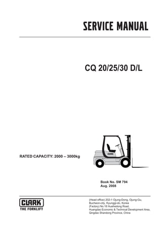
  • 1. CQ 20/25/30 D/L SERVICE MANUAL RATED CAPACITY: 2000 ā€“ 3000kg Book No. SM 794 Aug. 2008
  • 2. Truck Models Covered by this Manual This manual consists of ā€œbaseā€ module that pertains to all CQ20-30 models and other modules that per- tain only to specific models. Manuals shipped with the truck contain the base module and the modules specific to the purchased truck. You may, however, purchase specific modules and expand your manual to fully cover multiple models. To do so, order the desired modules as you would any other Clark part. Arrangement and Use of this Manual Clark arranges parts and service procedures by stan- dardized Groups. In this manual, Groups are similar to ā€œchaptersā€. Each Group begins with a table of contents that shows the Sections contained within the Group. Lengthy Sections also begin with a table of contents. Each Group and Section has an identifying name and number, or ā€œIDā€. Each page also has a unique ID. The page ID con- sists of three numbers separated by hyphens. The three numbers represent the Group number, the Sec- tion number, and the page number. For example, ā€œ00-1-2ā€ on the lower corner of the page indicates Group 00, Section 1, page 2. The Group number sometimes has a letter or letters added to it in parentheses if one or more variations of the Group exist. For example, if the truck has a stan- dard transaxle, Group 06 is expressed as ā€œ06(S)ā€; if the truck has a hydrostatic transmission, Group 06 is expressed as ā€œ06(H)ā€. You can quickly locate a specific point in the manual by using the headers and footers that appear on every Section page. The following illustration points out these areas. This manual is intended for the use of trained service personnel. Please read Group SA, ā€œSafe Mainte- nanceā€, and the Operatorā€™s Manual before working on or operating the truck. Manual ID Group-Section-Page Group ID
  • 3. CONTENTS SM 794 CONTENTS CONTENTS (Group Index) Group PS. Periodic Service Group 00. Engines Group 01. Cooling System Group 02. Fuel System Group 03. Air Induction System Group 06. Transaxle Group 12. Ignition System Group 13. Electrical System Group 22. Wheels and Tires Group 23. Brake / Inching System Group 25. Steering Column and Gear Group 26. Steer Axle Group 29. Hydraulic Pump, Sump, and Filters Group 30. Hydraulic Control Valve/Lift Circuit Group 32. Tilt Cylinders Group 34. Upright Group 38. Counterweight, Sheet Metal & Chassis 23 30 29 13 00 03 02 22 38 06 25 32 34 26 01 13
  • 4. GROUP PS SM 794 PS-0 GROUP PS PERIODIC SERVICE Maintenance Schedules ............................ Section 1 The Planned Maintenance Program ....... Section 2
  • 5. Group PS, Periodic Service SM 794 PS-1-1 ā€œPeriodic Serviceā€ and ā€œPlanned Maintenanceā€ The term ā€œperiodic serviceā€ includes all maintenance tasks that should be performed on a regularly scheduled basis. The term ā€œPlanned Maintenanceā€ indicates a formalized program of basic inspections, adjustments, and lubrica- tions that the Clark service organization provides custom- ers at a prescribed interval, usually 50-250 hours. The recommended basic ā€œPlanned Maintenanceā€ procedure is given in Section 2 of this Group. The current Section,ā€œMaintenance Schedules,ā€ specifies all maintenance tasksā€”including Planned Maintenance tasksā€”that should be performed periodically, and sug- gests intervals at which they should be performed. Determining Maintenance Intervals Time intervals on the charts on the next four pages and elsewhere in this manual relate to truck operating hours as recorded on the hourmeter, and are based on experience Clark has found to be convenient and suitable under nor- mal operation. Standard operating condition classifica- tions are: Normal Operation: Eight-hour material handling, mostly in buildings or in clean, open air on clean, paved surfaces. Severe Operation: Prolonged operating hours or constant usage. Extreme Operation: ā€¢ In sandy or dusty locations, such as cement plants, lumber mills, and coal dust or stone crushing sites. ā€¢ High-temperature locations, such as steel mills and foundries. ā€¢ Sudden temperature changes, such as constant trips from buildings into the open air, or in refrigeration plants. If the lift truck is used in severe or extreme operating con- ditions, the maintenance intervals should be shortened accordingly. IMPORTANT MAINTENANCE INTERVALS. If the lift truck is used in severe or extreme operating conditions, the maintenance intervals should be shortened accordingly. Since the operating environments of lift trucks vary widely, the above descriptions are highly generalized and should be applied as actual conditions dictate. Section 1 Maintenance Schedules
  • 6. Group PS, Periodic Service SM 794 PS-1-2 LUBRICATION Perform periodic maintenance, replacement and lubricating according to following lubrication chart to maintain optimum condition. Otherwise service, life will be reduced and breakdowns may occur frequently. LUBRICATION CHART Lubricant Replace Check Grease Engine oil Transaxle oil Antifreeze Hydraulic oil Fuel Brake fluid CO HO G EO EO BO BO TO TO EO CO CO G G FO HO HO G G EO TO FO BO Every 10 hours or daily Every 200 hours or monthly Every 500 hours or every 3 months Every 1000 hours or every 6 months Every 2000 hours or yearly Transaxle oil filter Mast mounting RH, LH(2points) Lift chain RH, LH(2points) Brake fluid Transaxle oil Engine oil Engine oil filter Coolant Steer king pin RH, LH(4points) Steering linkage RH, LH(4points) Fuel (LPG) Tilt cylinder end RH, LH(2points) Hydraulic oil Hydraulic oil filter Hydraulic breather Wheel bearing RH, LH(2points) Air cleaner
  • 7. GROUP 06 SM 794 06-0 Structure and Maintenance......................Section 1 Disassembly................................................Section 2 Assembly......................................................Section 3 GROUP 06 TRANSAXLE
  • 8. Group 06, TRANSAXLE SM 794 06-1-1 Construction TA18 Transaxle assembly includes: ā€¢ Torque converter ā€¢ Singleā€“speed forward and reverse powershift transmission with integral differential and drive axle ā€¢ Fullā€“floating straight drive axle ā€¢ Automotiveā€“type drum and shoe brakes ā€¢ Gearā€“driven pump drive ā€¢ Electric shift control, hydraulic inching control Power flow is from torque converter turbine, to tur- bine (clutch) shaft and gears, then through either for- ward gear or reverse idler shaft, to the output gear mounted on final drive pinion shaft. Transmission and differential are housed in a oneā€“ piece transmission case. Torque converter housing joined to transmission case through an adaptor (or spacer) plate holds the converter stator support and reverse idler outer bear- ing. Pump drive is from converter impeller hub gear, through an idler gear to the pump gear mounted on charging pump shaft. Final drive pinion gear shaft, mounted in tapered roller bearings at both ends in transmission case, is adjusted for mounting distance, and ring and pinion gear contact by, shim a pack installed behind the pin- ion gear inner tapered roller bearing cup in the trans- misson case. Pinion shaft bearing preload is adjusted with shims behind outer bearing cone on the pinion shaft. Section 1 Structure and Maintenance
  • 9. Group 06, TRANSAXLE SM 794 06-1-2 Final drive ring gear is bolted to differential carrier. Differential support is by opposed tapered roller bearings mounted on inner end of wheel end hous- ings, which are bolted to openings in transmission case at the sides of the differential. Differential bear- ing preload and ring gear clearance (backlash) is maintained by shims placed behind differential bear- ing cones on wheel end housings. Adjustment of dif- ferential bearing preload or ring gear backlash requires trial assembly, checking, and disassembly of wheel end housings until correct adjustment is obtained. Drive axle wheel hubs/brake drums are supported by double tapered roller bearings on outer end of wheel end housings. Drive axle shaft flange bolted to wheel hubs are fullā€“floating in differential. Service brake backing plates are bolted to mounting flanges on wheel end housings. Wheel bearings are lubricated from the transaxle sump. Control valve is mounted on pad at top of transmis- sion case. Oil from charging pump flows via filter and pressure regulator to control valve through an exter- nal oil supply line. Oil from control valve is delivered to clutches through passages in housing and oil dis- tributor sleeve and seal rings at forwardā€“clutch end of turbine/clutch shaft. Excess pump oil volume and converterā€“out oil, flows to oil cooler and returns to transmission housing at base of control valve, then through center of turbine/clutch shaft back to con- verter. Hydraulic Circuit
  • 10. Group 06, TRANSAXLE SM 794 06-1-3 Service Maintenance Service The transaxle has two service openings: 1. Dipstick / oil fill tube in central side axle housing. 2. Drain plug, in bottom of transmission case. Fluid Level Check Check the transaxle fluid level with: ā€¢ Fork lift on a level surface ā€¢ Engine idling with transmission in NEUTRAL ā€¢ Oil at operating temperature 82~93Ā°C (180~200Ā°F) ā‘  Remove the transaxle oil level plug the front of central housing of driving wheel. ā‘” The oil level is correct when the oil reaches the full mark on dipstick. ā‘¢ Add recommended fluid only, as required. Fluid and Filter Change It is recommended to: ā€¢ Drain and replace the transaxle fluid every 1000 operating hours. ā€¢ The oil should be drained when warmed to oper- ating temperature, 82~93Ā°C (180~200Ā°F) ā€¢ Replace the transaxle oil filter every 1000 oper- ating hours. See NOTICE below. IMPORTANT When the transaxle is new or rebuilt, it is rec- ommended to change the oil filter after the first 50 hours and again after 1000 operating hours. ā‘  Remove drain plug from bottom of transmission case. Drain old oil into suitable drain pan. ā‘” Remove old oil filter. The oil filter is mounted near the top of converter housing above trans- mission. Take special care when removing the filter to avoid oil remaining in filter from draining onto floor. Loosen the filter using a filter wrench. Remove filter while holding a pad of cloth or other absorbent material under the open end to absorb any excess oil that may drain out of filter. ā‘¢ Install a new oil filter. Follow the installation instructions printed on filter. Always use genuine CLARK parts ! ! !
  • 11. Group 06, TRANSAXLE SM 794 06-1-4 Refilling the Transaxle After drive axle and transmission housing has drained completely, ā€¢ Install drain plug. ā€¢ Loosen the oil level plug and fill the oil upto the plug hole. ā€¢ Start the engine and run at idle speed (700~800 rpm) in NEUTRAL for 2~3 minutes to prime the converter and cooler lines. ā€¢ Recheck oil level with engine running at idle speed. [82~93Ā°C (180~200Ā°F)] ā€¢ Check for leaks at drain plug and oil filter. Specification Pressure Specification ā€¢ Regulator valve pressure : 1108~1451kPa (160~210 psi) @ 1800 rpm Check Point : Oil supply line at converter ā€¢ Converter In/Lube Pressure : 176~314kPa (26~45 psi ) @ 1800 rpm Check Point : Return from cooler ā€¢ Converter Safety Valve Pressure (Trans in NEU- TRAL) : 729~827kPa (105~120 psi) @ 1800 rpm (Refefence only) with line to cooler blocked. Check Point : None ā€¢ Clutch Pressure (Forward, Reverse applied) : 1034kPa (150 psi) @ 700~800 rpm idle Normally 103kpa (15 psi) less than regulator pressure 1000kpa (145 psi min) Check Point : At control valve (1/8 NPTF) ā€¢ Clutch Pressure (in NEUTRAL) : Regulator pres- sure
  • 12. Group 06, TRANSAXLE SM 794 06-1-5 NOTICE ! ā€¢ All rpmā€™s noted are engine speed. ā€¢ All clutch pressures are at engine idle speed with clutch engaged, unless otherwise noted. ā€¢ Oil at operating temperature 82~93C(180~200F) ā€¢ Refer to following illustrations for check point locations. Pressure Check Points
  • 13. Group 06, TRANSAXLE SM 794 06-1-6 Service Brake Adjustment Preparation 1. The service brakes on the transaxle may be adjusted from the inner side through the backing plate (all models), or from the outer side through access openings in the wheel hub/brake drum (later models). 2. Brake clearance is measured between brake shoe and drum, with brakes fully released. Brake clearance : 0.255~0.304 mm (.010~.012 in) CAUTION ! Be sure transmission directional control is in NEUTRAL and fork lift prevented from moving when parking brake is released. 3. Release parking brake. IMPORTANT ! Do not overtighten brakes. It is very difficult to release the ratchet wheel pawl and back off adjustment of the brake. Adjustment at Backing Plate 1. Remove the 4 dust plugs in brake backing plate. 2. Use a feeler (thickness) gauge to check the clearance between each shoe and drum. Use a brake adjuster tool to rotate the adjuster ratchet wheel in the brake. 3. Use a screwdriver to push on and release the ratchet pawl when it is necessary to back off adjustment (increase clearance) of the brake. 4. Carefully adjust clearance between brake shoes and drum to 0.255~0.304 mm (.010~.012 in) measured at dust plug openings at outer sides of backing plate. 5. Replace the dust plugs in brake backing plate when adjustment is completed.
  • 14. Group 06, TRANSAXLE SM 794 06-1-7 Adjustment at Wheel Hub Openings in the wheel hub/brake drum have been provided for easier access to check and adjust the service brakes from the outer side. Requires removal of drive wheel and tire assembly. Some models may have only a slot for measuring brake clearance ; adjustment is made through the plug openings on backing plate. Later models have a slot and circular opening for access also to the adjuster. The opening is enclosed with a dust cover held in place by a single screw. 1. Remove wheel and tire assembly from wheel hub. WARNING ! Pneumatic Tire Wheels Before loosening wheel mounting bolts or nuts, release the air pressure from the tire. Failure to release the air pressure from the tire can result in serious injury or death. 2. Remove dust cover from access opening in wheel hub/brake drum. 3. Use feeler (thickness) gauge to check the clear- ance between each shoe and drum. Use a brake adjuster tool to rotate the adjuster ratchet wheel in the brake. 4. Use a tool with a hook to pull on and release the ratchet pawl when it is necessary to back off adjustment (increase clearance) of the brake. IMPORTANT ! Do not overtighten brakes. It is very difficult to release the ratchet wheel pawl and back off adjustment of the bake. 5. Carefully adjust clearance between brake shoes and drum to 0.255~0.304 mm (.010~.012 in) measured at slot opening. Move slot by rotating brake drum to check clearance at the illustrated position for each brake shoe. (20ā€“01ā€“6) 6. After adjusting brakes, install dust cover over access opening in the wheel hub. 7. Install wheel and tire assembly on the drive axle wheel hub. 8. Install wheel mounting lug nuts and tighten to spec : 637~718 Nm (471~531 lbfĀ·ft)
  • 15. Group 06, TRANSAXLE SM 794 06-2-1 Precaution ā€¢ Before attempting any repairs or overhaul of this assembly, please read through the entire disassembly and assembly procedures first. Cleanliness is of extreme importance in the repair and overhaul of this assembly. ā€¢ The exterior surface of the unit MUST be thor- oughly cleaned of all dirt and foreign substances to prevent contamination of the parts during dis- assembly and overhaul. Perform all disassembly and assembly work in a clean area. Protect all components from dust and dirt while repairs are being made. ā€¢ Keep all parts in order as disassembly progresses. Take care to properly identify each part and its order of removal. If necessary, keep notes and put marking on parts using a nonde- structive marker such as a feltā€“tipped pen. Remove Auxiliary Subassemblies 1. Remove torque converter assembly by carefully sliding it off the turbine (clutch) shaft and stator support. 2. Disassemble converter drive plate and adaptor, as needed. Remove the : 3. Oil filter 4. Charging pump 5. Oil supply line assembly 6. Transmission control valve assembly ! Section 2 Disassembly
  • 16. Group 06, TRANSAXLE SM 794 06-2-2 Wheel End 1. Loosen and remove the axle shaft fasteners. 2. Remove axle shaft. 3. Unbend (straighten) the lockplate tabs from the bolt heads of the wheel bearing retainer plate fasteners. 4. Remove the bearing retainer plate fasteners. 5. Remove the lockplate, bearing retainer plate and wheel bearing shims. 6. Pull wheel hub out to loosen bearing (you may have to tap on hub or pry at brake backing plate), remove outer wheel bearing, then remove the wheel hub/brake drum assembly with inner wheel bearing and oil seal. 8 7 4 6 5 3 2 1
  • 17. Group 06, TRANSAXLE SM 794 06-2-3 IMPORTANT ! This oil seal is a type that seals internally, and is lined with sealing compound on the inner diame- ter that sticks and seals to the spindle. Removing the wheel hub from the spindle breaks that seal. Replace with new seal each time that the wheel hub is removed from wheel end hous- ing. 7. Before removal of wheel end housing, mark the housing and the transmission case for sameā€“ location matching at reassembly. Loosen and remove the housing bolts and washers. 8. Remove wheel end housing from transmission case. 9. If the differential bearing on the inner end of the wheel end housing is to be removed and replaced, use a bearing puller, if necessary. Wire bearing shims to wheel end housing for storage until reassembly. 10. Repeat procedures of Steps 1 through 9 for opposite wheel end disassembly. 11. Remove the differential assembly from trans- mission case.
  • 18. Group 06, TRANSAXLE SM 794 06-2-4 Brake Assembly Removal Brake removal is optional for brake overhaul as nec- essary. 1. Remove the upper brake shoe return springs. 2. Remove lower return spring. 3. Remove brake shoe holdā€“down (guide) springs. 4. Disconnect parking brake cable. Remove the brake shoes. 5. Remove brake backing plate fasteners and washers. 6. Remove backing plate and parking brake cable assembly from wheel end housing. 7. Remove drive axle support and spacer from wheel end housing.
  • 19. Group 06, TRANSAXLE SM 794 06-2-5 Separation of Converter Housing and Adaptor Plate 1. Remove the fasteners and washers which mount the converter housing to transmission case through the adaptor plate. 2. From other side, remove the bolts and washers which mount adaptor (spacer) plate to converter housing. 3. Remove the clutch pressureā€“regulating valve assembly (also oil filter mounting base). IMPORTANT ! Pry only at the dowel pins to remove adap- tor plate. Dowel pins must be removed before reassembly. See later instructions. 4. Separate converter housing from adaptor plate. 5. Remove impeller hub gear from stator support. 6. Remove pump drive idler gear and bearing, outer and inner thrust washers, and idler shaft. 7. Remove adaptor plate from transmission case. Stator Support Removal From Adaptor Plate 1. The stator support is held in place by two retain- ing rings, one on each side of the adaptor plate. 2. To remove stator support : āˆ’ Remove front (converter end) retaining ring from ring groove and move ring and impeller gear thrust washer toward stator support seal surface. āˆ’ Push stator support to the rear (towards trans- mission side) far enough to expose rear retainer ring. āˆ’ Remove rear retaining ring. āˆ’ From the front, pull stator support from adaptor plate.
  • 20. Thank you very much for your reading. Please Click Here. Then Get COMPLETE MANUAL. NO WAITING NOTE: If there is no response to click on the link above, please download the PDF document first and then click on it.
  • 21. Group 06, TRANSAXLE SM 794 06-2-6 Clutch Assembly, Idler Gear & Pin- ion Shaft Removal 1. Move the reverse idler gear and clutch assem- bly apart far enough to allow the idler shaft to be pulled out of the inner bearing. 2. Remove the clutch assembly and reverse idler shaft together. 3. Remove the turbine (clutch) shaft rear bearing. 4. Remove the clutch shaft oil distributor retaining set screw (internal hex) from valve mounting base. 5. Remove the oil distributor. Note the recess in distributor for retaining set screw. 6. Loosen and remove the pinion shaft nut. Hold or block the pinion shaft with a brass bar or similar soft material to prevent turning. 7. Remove the pinion shaft outer bearing and shims. Keep the shims with the bearing and pin- ion shaft. 8. Remove output gear retaining ring from pinion shaft (inside transmission case). 9. Remove output gear (move pinion shaft away). 10. Remove pinion shaft and inner bearing through differential housing. 11. If pinion bearings are to be replaced, drive the cups from the housing inside transmisson case. 12. Remove inner pinion bearing cup and shims from differential side. Wire shims to transmission housing for stor- age until reassembly. 13. As required, remove oil suction (pickup) tube assembly from transmission case. !
  • 22. Group 06, TRANSAXLE SM 794 06-2-7 Clutch Disassembly (Forward & Reverse Clutch Procedure Are The Same) ā€¢ Reverse Clutch Disassembly Illustrated 1. Remove outer clutch hub gear thrust bearing and thrust washers, clutch hub gear, and inner clutch hub thrust bearing and thrust washers. 2. Disassemble the two clutch gear bearings and spacer from internal bore of clutch gear hub. 3. Remove clutch disc end plate retainer ring and clutch disc end plate. 4. Remove inner and outer clutch discs. 5. Remove clutch return spring retainer ring. 6. Remove clutch return (release) springs (Belleville washers). Note assembly arrange- ment. 7. Remove clutch piston wear plate. 8. Remove clutch piston by turning clutch upside down and tapping the shaft on a block of wood. 9. Remove and discard clutch piston sealing rings. 10. Repeat procedures, steps 1 through 9, for for- ward clutch disassembly.
  • 23. Group 06, TRANSAXLE SM 794 06-2-8 Differential Disassembly 1. Use a small drift pin or rod to remove the differ- ential pinion pin, lock pin. 2. Remove the pinion pin. 3. Rotate the pinion gears and washers to remove them from the differential housing.