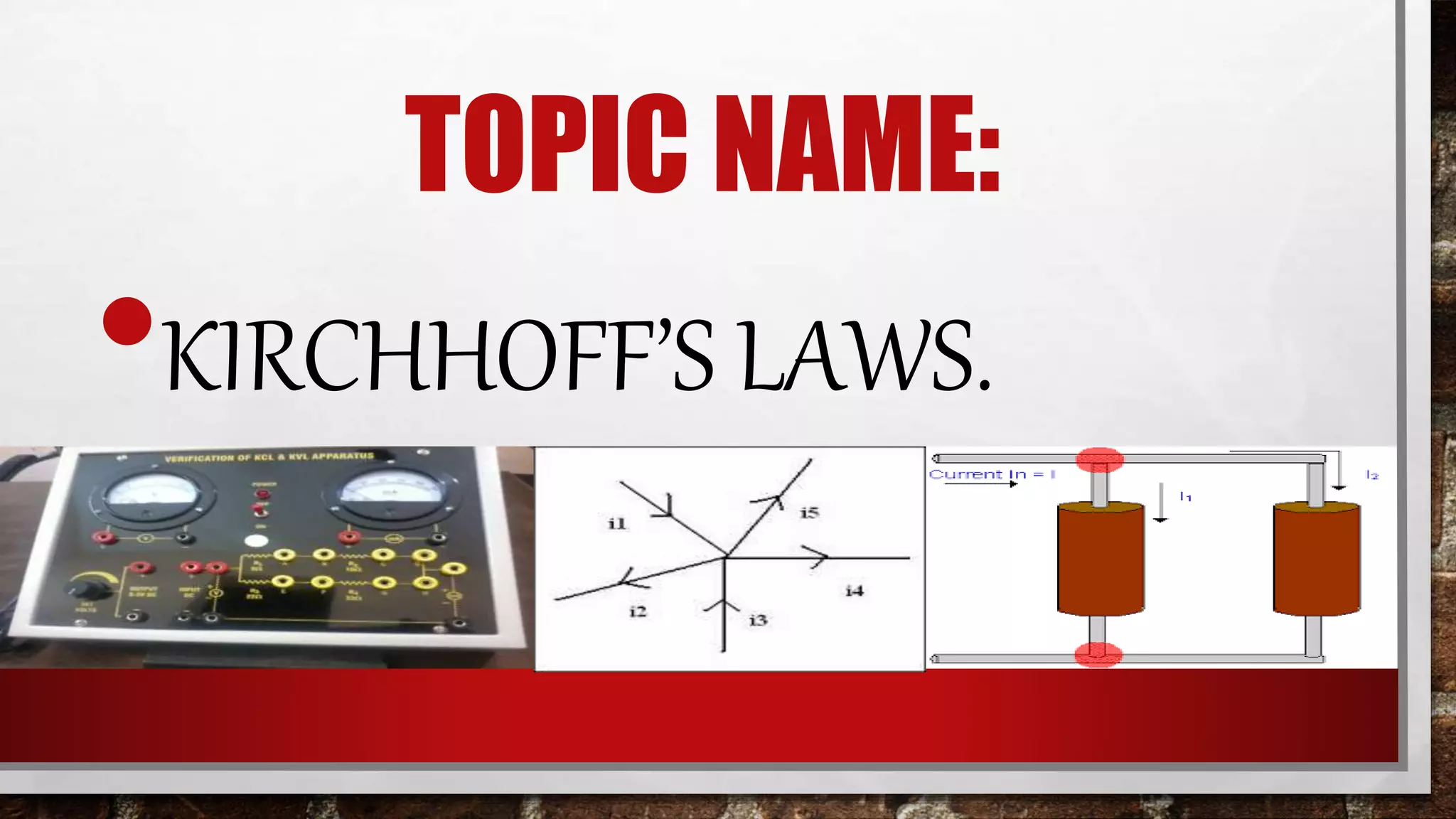
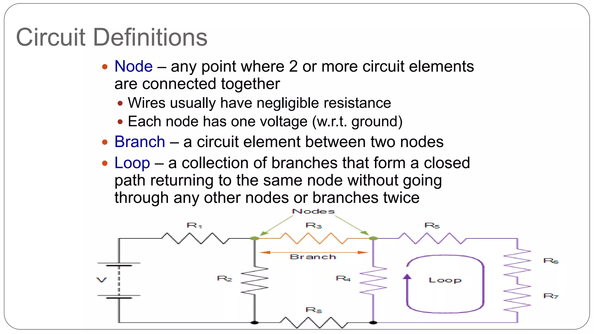
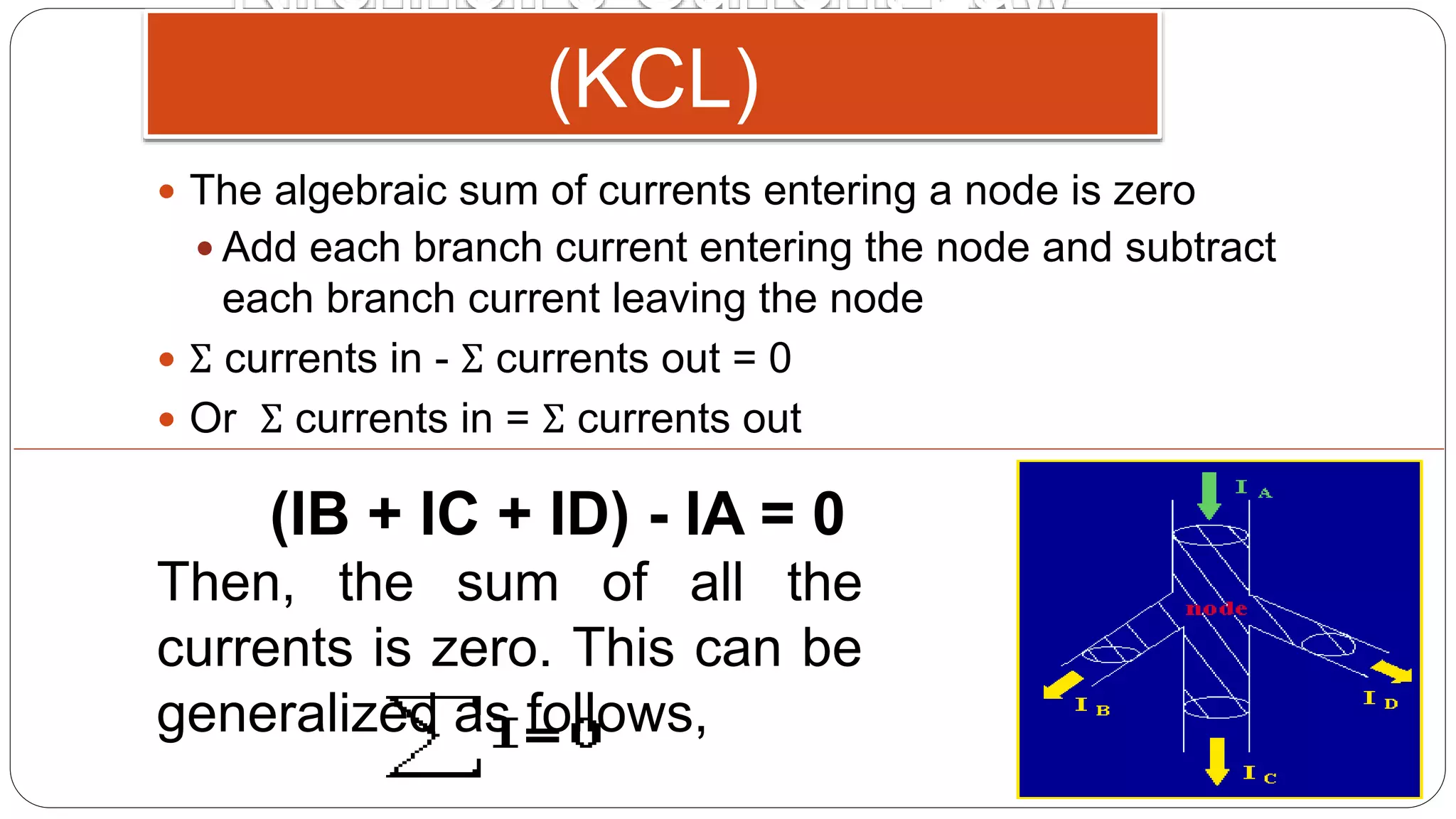
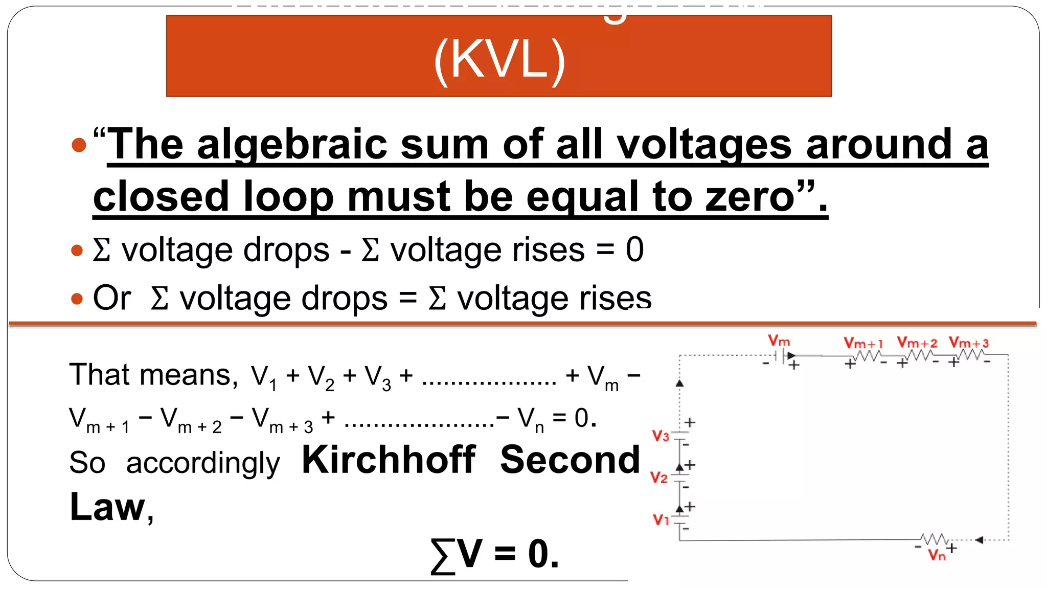
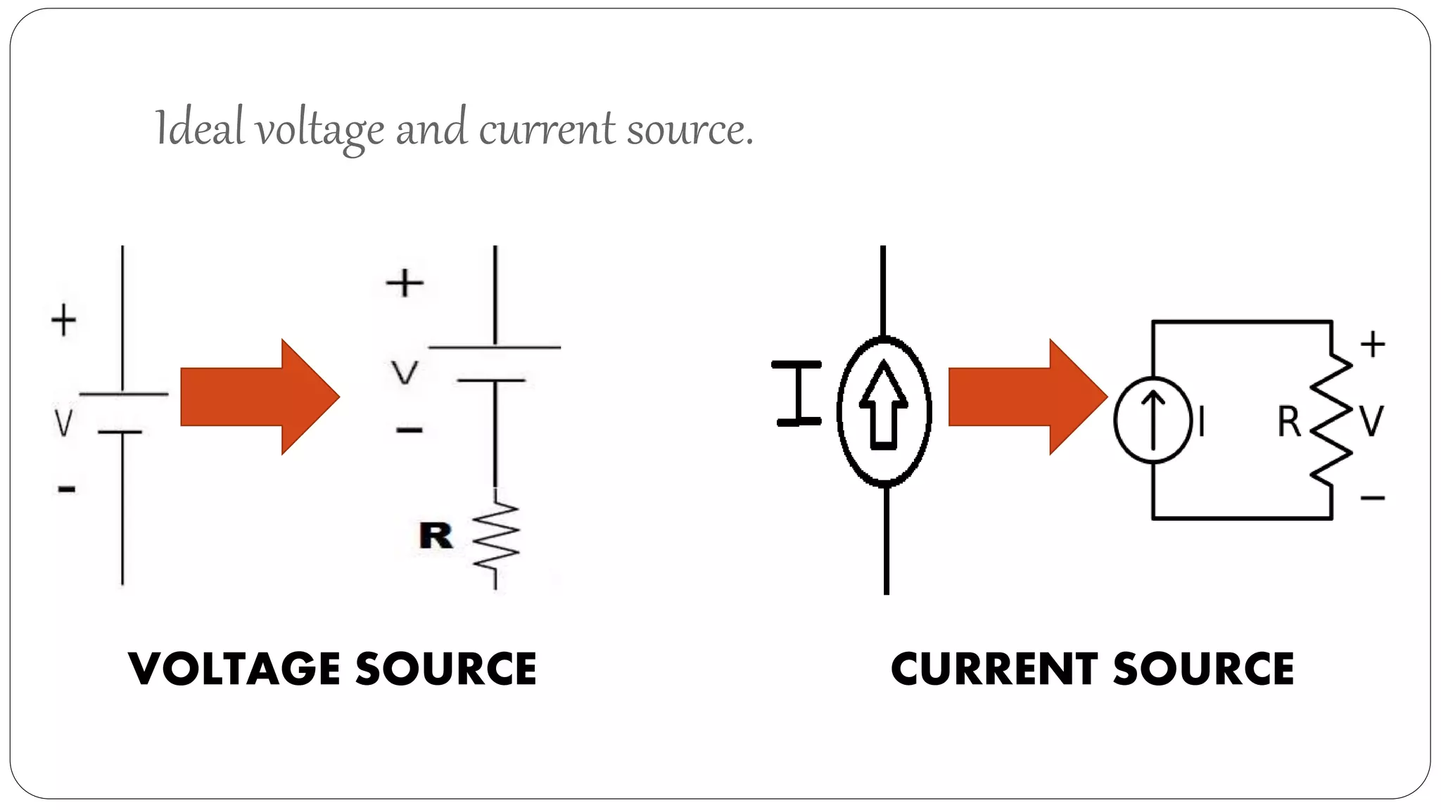
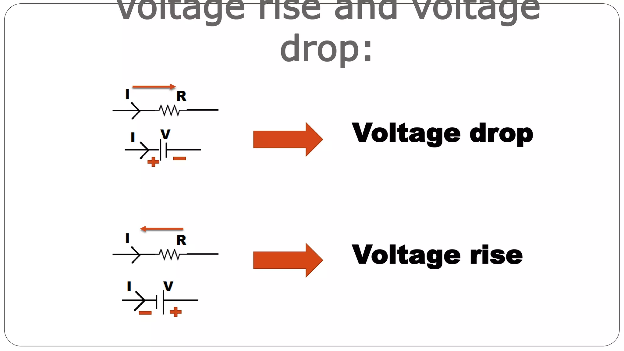
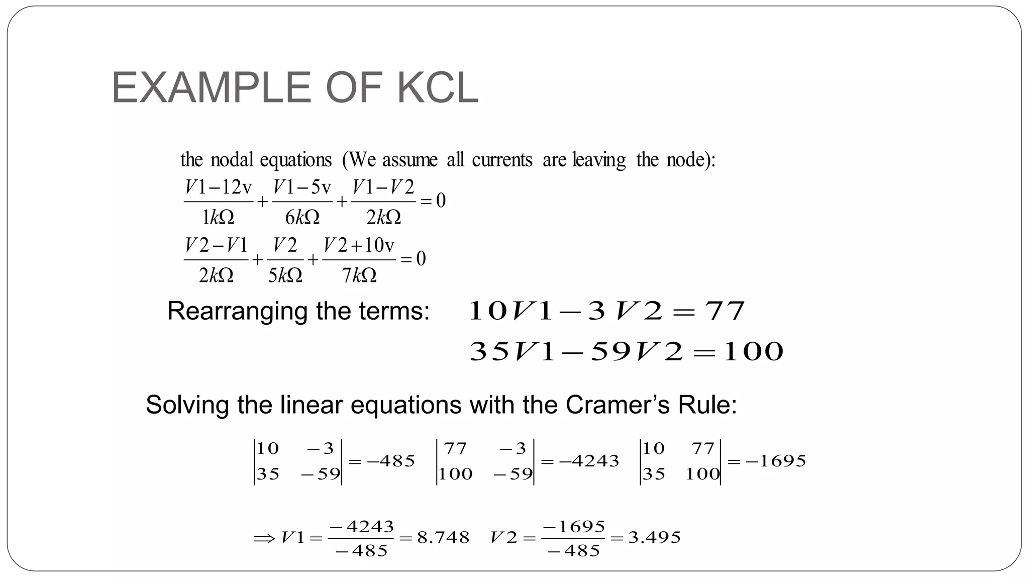
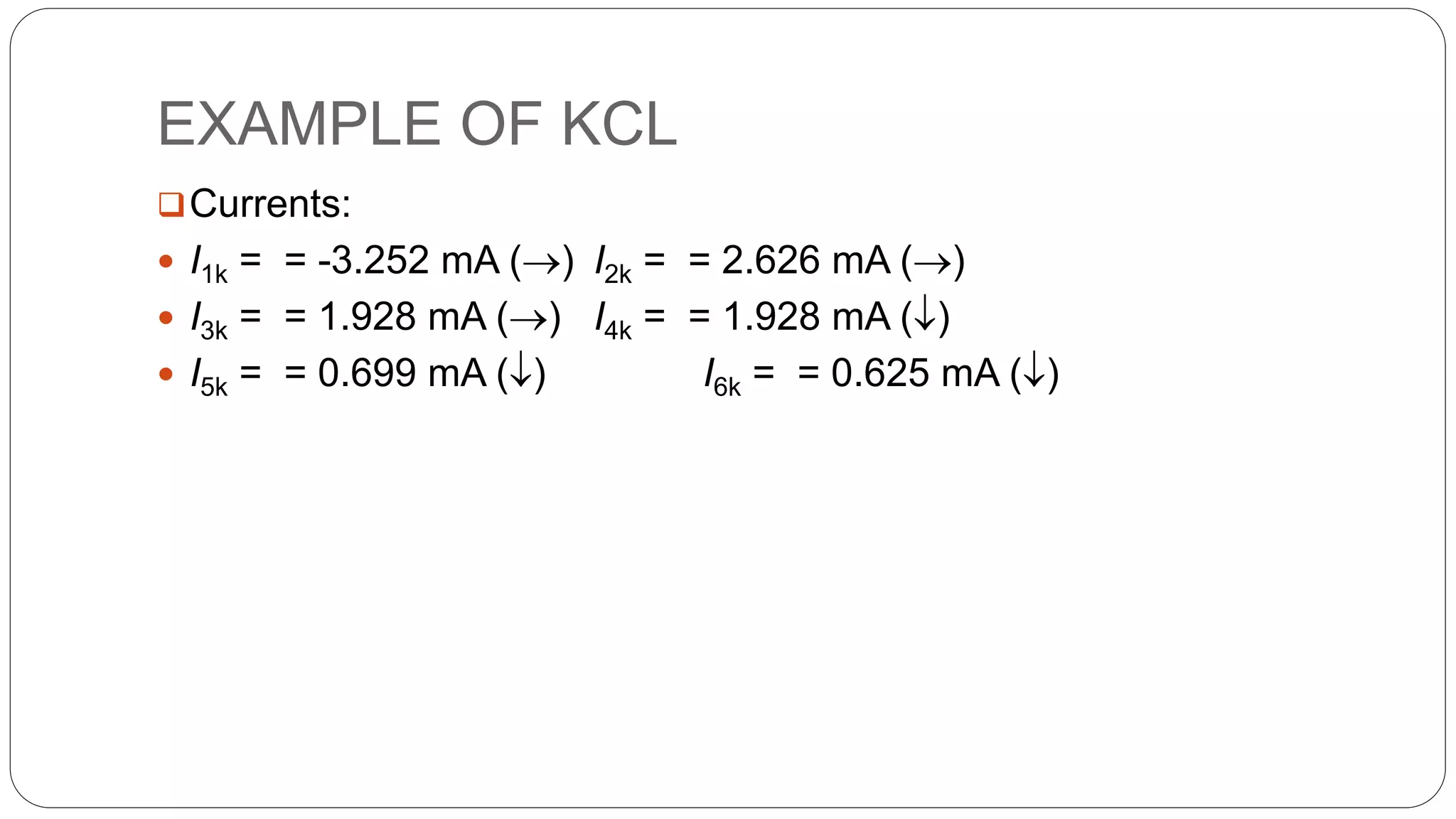
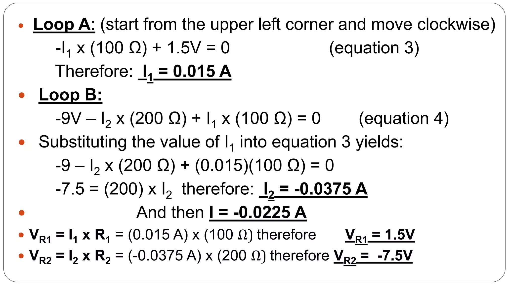
ACTIVELEARNINGASSIGnMENT
CIRCUITS AND NETWORKS(2130901)
Prepared by
Group - 1
Div- B
Sem-3rd
Branch-Electrical
Guided by: Prof. Megha Ma’m
GANDHINAGAR INSTITUTE OF Technology.
Brijesh Patel -140120109030
Kavan Patel -140120109032
Darshil Shah -140120109050
Group : 1
PREPAREDBY:
ENROLLMENTNO.
TOPIC NAME:
•KIRCHHOFF’S LAWS.
TYPES OF LAWS:
Kirchhoff’s laws.
KIRCHHOFF’S CURRENT LAW(KCL) KIRCHHOFF’S VOLTAGE LAW (KVL)
These laws are first derived by Guatov Robert
Kirchhoff and hence these laws are also referred
as Kirchhoff Laws.
Circuit Definitions
 Node – any point where 2 or more circuit elements
are connected together
 Wires usually have negligible resistance
 Each node has one voltage (w.r.t. ground)
 Branch – a circuit element between two nodes
 Loop – a collection of branches that form a closed
path returning to the same node without going
through any other nodes or branches twice
Kirchhoff's Current Law
(KCL)
 The algebraic sum of currents entering a node is zero
 Add each branch current entering the node and subtract
each branch current leaving the node
 Σ currents in - Σ currents out = 0
 Or Σ currents in = Σ currents out
(IB + IC + ID) - IA = 0
Then, the sum of all the
currents is zero. This can be
generalized as follows,
Kirchhoff's Voltage Law
(KVL)
“The algebraic sum of all voltages around a
closed loop must be equal to zero”.
 Σ voltage drops - Σ voltage rises = 0
 Or Σ voltage drops = Σ voltage rises
That means, V1 + V2 + V3 + ................... + Vm −
Vm + 1 − Vm + 2 − Vm + 3 + .....................− Vn = 0.
So accordingly Kirchhoff Second
Law,
∑V = 0.
Ideal voltage and current source.
VOLTAGE SOURCE CURRENT SOURCE
Voltage rise and voltage
drop:
Voltage drop
Voltage rise
Example.
 Find the current through 8Ω resistor using KIRCHHOFF’S LAWS.
EXAMPLE OF KCL
EXAMPLE OF KCL
the nodal equations (We assume all currents are leaving the node):
0
7
v102
5
2
2
12
0
2
21
6
v51
1
v121

















k
V
k
V
k
VV
k
VV
k
V
k
V
Rearranging the terms:
Solving the linear equations with the Cramer’s Rule:
100259135
7723110


VV
VV
495.3
485
1695
2748.8
485
4243
1
1695
10035
7710
4243
59100
377
485
5935
310













VV
EXAMPLE OF KCL
Currents:
 I1k = = -3.252 mA () I2k = = 2.626 mA ()
 I3k = = 1.928 mA () I4k = = 1.928 mA ()
 I5k = = 0.699 mA () I6k = = 0.625 mA ()
EXAMPLE OF KVL
EXAMPLE OF KVL
 Junction J1:
I = I1 + I2 (equation 1)
 Junction J2:
I1 + I2 = I (equation 2)
 Loop A: (start from the upper left corner and move clockwise)
-I1 x (100 Ω) + 1.5V = 0 (equation 3)
Therefore: I1 = 0.015 A
 Loop B:
-9V – I2 x (200 Ω) + I1 x (100 Ω) = 0 (equation 4)
 Substituting the value of I1 into equation 3 yields:
-9 – I2 x (200 Ω) + (0.015)(100 Ω) = 0
-7.5 = (200) x I2 therefore: I2 = -0.0375 A
 And then I = -0.0225 A
 VR1 = I1 x R1 = (0.015 A) x (100 Ω) therefore VR1 = 1.5V
 VR2 = I2 x R2 = (-0.0375 A) x (200 Ω) therefore VR2 = -7.5V
REFERENCES.
www.electricals4u.com
www.eefundamentals.com
www.electricaleasy.com
www.wikipedia.com/KCL,KVL
CIRCUITS & NETWORKS book
KCL and KVL

KCL and KVL

  • 1.
    ACTIVELEARNINGASSIGnMENT CIRCUITS AND NETWORKS(2130901) Preparedby Group - 1 Div- B Sem-3rd Branch-Electrical Guided by: Prof. Megha Ma’m GANDHINAGAR INSTITUTE OF Technology.
  • 2.
    Brijesh Patel -140120109030 KavanPatel -140120109032 Darshil Shah -140120109050 Group : 1 PREPAREDBY: ENROLLMENTNO.
  • 3.
  • 4.
    TYPES OF LAWS: Kirchhoff’slaws. KIRCHHOFF’S CURRENT LAW(KCL) KIRCHHOFF’S VOLTAGE LAW (KVL) These laws are first derived by Guatov Robert Kirchhoff and hence these laws are also referred as Kirchhoff Laws.
  • 5.
    Circuit Definitions  Node– any point where 2 or more circuit elements are connected together  Wires usually have negligible resistance  Each node has one voltage (w.r.t. ground)  Branch – a circuit element between two nodes  Loop – a collection of branches that form a closed path returning to the same node without going through any other nodes or branches twice
  • 6.
    Kirchhoff's Current Law (KCL) The algebraic sum of currents entering a node is zero  Add each branch current entering the node and subtract each branch current leaving the node  Σ currents in - Σ currents out = 0  Or Σ currents in = Σ currents out (IB + IC + ID) - IA = 0 Then, the sum of all the currents is zero. This can be generalized as follows,
  • 7.
    Kirchhoff's Voltage Law (KVL) “Thealgebraic sum of all voltages around a closed loop must be equal to zero”.  Σ voltage drops - Σ voltage rises = 0  Or Σ voltage drops = Σ voltage rises That means, V1 + V2 + V3 + ................... + Vm − Vm + 1 − Vm + 2 − Vm + 3 + .....................− Vn = 0. So accordingly Kirchhoff Second Law, ∑V = 0.
  • 8.
    Ideal voltage andcurrent source. VOLTAGE SOURCE CURRENT SOURCE
  • 9.
    Voltage rise andvoltage drop: Voltage drop Voltage rise
  • 10.
    Example.  Find thecurrent through 8Ω resistor using KIRCHHOFF’S LAWS.
  • 11.
  • 12.
    EXAMPLE OF KCL thenodal equations (We assume all currents are leaving the node): 0 7 v102 5 2 2 12 0 2 21 6 v51 1 v121                  k V k V k VV k VV k V k V Rearranging the terms: Solving the linear equations with the Cramer’s Rule: 100259135 7723110   VV VV 495.3 485 1695 2748.8 485 4243 1 1695 10035 7710 4243 59100 377 485 5935 310              VV
  • 13.
    EXAMPLE OF KCL Currents: I1k = = -3.252 mA () I2k = = 2.626 mA ()  I3k = = 1.928 mA () I4k = = 1.928 mA ()  I5k = = 0.699 mA () I6k = = 0.625 mA ()
  • 14.
  • 15.
    EXAMPLE OF KVL Junction J1: I = I1 + I2 (equation 1)  Junction J2: I1 + I2 = I (equation 2)
  • 16.
     Loop A:(start from the upper left corner and move clockwise) -I1 x (100 Ω) + 1.5V = 0 (equation 3) Therefore: I1 = 0.015 A  Loop B: -9V – I2 x (200 Ω) + I1 x (100 Ω) = 0 (equation 4)  Substituting the value of I1 into equation 3 yields: -9 – I2 x (200 Ω) + (0.015)(100 Ω) = 0 -7.5 = (200) x I2 therefore: I2 = -0.0375 A  And then I = -0.0225 A  VR1 = I1 x R1 = (0.015 A) x (100 Ω) therefore VR1 = 1.5V  VR2 = I2 x R2 = (-0.0375 A) x (200 Ω) therefore VR2 = -7.5V
  • 17.