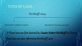
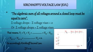
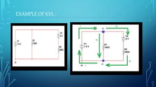
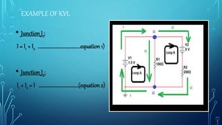
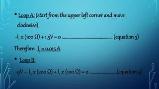
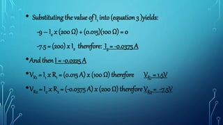
PRESENTATION ON
KIRCHHOFF’S VOLTAGE LAW
(KVL)
COURSETITLE : BASICELCTRICALENGINEERING(BEE)
COURSECODE : CSE- 106
SUBMITTEDBY :
NAME : NAFISA ELLAHI
ID : 2016-2-17-006
DEPT : CSE
Submitted to:
DR.AIN-UL-
HUDA
TYPES OF LAWS:
Kirchhoff’s laws.
KIRCHHOFF’S CURRENT LAW(KCL) KIRCHHOFF’S VOLTAGE LAW (KVL)
These laws are first derived by Guatov Robert Kirchhoff and hence
these laws are also referred as Kirchhoff Laws.
CIRCUIT DEFINITIONS
● Node– any point where 2 or more circuit elements are
connectedtogether
– Wires usually havenegligibleresistance
– Eachnode has one voltage(w.r.t. ground)
● Branch– a circuit element between two nodes
● Loop – a collection of branches that forma closed path
returning to the same node without going through any other
nodes or branches twice
KIRCHHOFF'S VOLTAGE LAW (KVL)
•
That means, V1 + V2 + V3 + ................... + Vm − Vm +
1 − Vm + 2 − Vm + 3 + .....................− Vn = 0.
So accordingly Kirchhoff Second Law,
∑V = 0.
“The algebraic sum of all voltages around a closed loop must be
equal to zero”.
Σ voltage drops - Σ voltage rises = 0
Or Σ voltage drops = Σ voltage rises
IDEAL VOLTAGE
VOLTAGE SOURCE
VOLTAGE RISE AND VOLTAGE DROP:
Voltage drop
Voltage rise
EXAMPLE OF KVL :
EXAMPLE OF KVL
• Junction J1:
I = I1 + I2 …………………………………equation 1)
• Junction J2:
I1 + I2 = I ………………………………(equation 2)
•Loop A: (start from the upper left corner and move
clockwise)
-I1 x (100 Ω) + 1.5V = 0 …………………………………………. (equation 3)
Therefore: I1 = 0.015 A
• Loop B:
-9V – I2 x (200 Ω) + I1 x (100 Ω) = 0 ………………….....(equation 4)
• Substituting the value of I1 into (equation 3 )yields:
-9 – I2 x (200 Ω) + (0.015)(100 Ω) = 0
-7.5 = (200) x I2 therefore: I2 = -0.0375 A
•And then I = -0.0225 A
•VR1 = I1 x R1 = (0.015 A) x (100 Ω) therefore VR1 = 1.5V
•VR2 = I2 x R2 = (-0.0375 A) x (200 Ω) therefore VR2 = -7.5V
Thanks For
Watching

Bee (kvl)

  • 1.
    PRESENTATION ON KIRCHHOFF’S VOLTAGELAW (KVL) COURSETITLE : BASICELCTRICALENGINEERING(BEE) COURSECODE : CSE- 106 SUBMITTEDBY : NAME : NAFISA ELLAHI ID : 2016-2-17-006 DEPT : CSE Submitted to: DR.AIN-UL- HUDA
  • 2.
    TYPES OF LAWS: Kirchhoff’slaws. KIRCHHOFF’S CURRENT LAW(KCL) KIRCHHOFF’S VOLTAGE LAW (KVL) These laws are first derived by Guatov Robert Kirchhoff and hence these laws are also referred as Kirchhoff Laws.
  • 3.
    CIRCUIT DEFINITIONS ● Node–any point where 2 or more circuit elements are connectedtogether – Wires usually havenegligibleresistance – Eachnode has one voltage(w.r.t. ground) ● Branch– a circuit element between two nodes ● Loop – a collection of branches that forma closed path returning to the same node without going through any other nodes or branches twice
  • 4.
    KIRCHHOFF'S VOLTAGE LAW(KVL) • That means, V1 + V2 + V3 + ................... + Vm − Vm + 1 − Vm + 2 − Vm + 3 + .....................− Vn = 0. So accordingly Kirchhoff Second Law, ∑V = 0. “The algebraic sum of all voltages around a closed loop must be equal to zero”. Σ voltage drops - Σ voltage rises = 0 Or Σ voltage drops = Σ voltage rises
  • 5.
  • 6.
    VOLTAGE RISE ANDVOLTAGE DROP: Voltage drop Voltage rise
  • 7.
  • 8.
    EXAMPLE OF KVL •Junction J1: I = I1 + I2 …………………………………equation 1) • Junction J2: I1 + I2 = I ………………………………(equation 2)
  • 9.
    •Loop A: (startfrom the upper left corner and move clockwise) -I1 x (100 Ω) + 1.5V = 0 …………………………………………. (equation 3) Therefore: I1 = 0.015 A • Loop B: -9V – I2 x (200 Ω) + I1 x (100 Ω) = 0 ………………….....(equation 4)
  • 10.
    • Substituting thevalue of I1 into (equation 3 )yields: -9 – I2 x (200 Ω) + (0.015)(100 Ω) = 0 -7.5 = (200) x I2 therefore: I2 = -0.0375 A •And then I = -0.0225 A •VR1 = I1 x R1 = (0.015 A) x (100 Ω) therefore VR1 = 1.5V •VR2 = I2 x R2 = (-0.0375 A) x (200 Ω) therefore VR2 = -7.5V
  • 11.