This document provides instructions for removing and installing the fuel injection pump on an excavator. Key steps include cleaning the pump area, removing lines and covers, aligning timing marks, and ensuring the new pump is installed at the correct timing based on markings and the timing numbers of the original and new pumps. Proper fuel injection pump timing is important for emissions compliance.
John Deere 35D Compact Excavator Service Repair Technical Manual (TM2264).pdflanji4905796341
This document provides instructions for removing and installing the fuel injection pump on a 35D and 50D excavator. Key steps include:
1. Cleaning the injection lines and area around the pump.
2. Removing the radiator, fan, and belt. Disconnecting fuel, coolant, and electrical lines from the pump.
3. Aligning timing marks on the pump gear and cover before removing the pump gear. Recording the pump timing number.
4. Installing the new pump, connecting all lines, and setting the timing based on the original and new pump timing numbers.
John Deere 50D Compact Excavator Service Repair Technical Manual (TM2264).pdflanji4905796341
This document provides instructions for removing and installing the fuel injection pump on a 35D and 50D excavator. Key steps include:
1. Cleaning the injection lines and area around the pump.
2. Removing the radiator, fan, and belt. Then removing the intake manifold.
3. Removing fuel and coolant lines from the pump. Aligning timing marks and removing the pump gear.
4. Installing the new pump by aligning timing marks, installing fuel and coolant lines, and reinstalling other components.
John Deere 50D Compact Excavator Service Repair Technical Manual (TM2264).pdfdongba082928
This document provides instructions for removing and installing fuel injection nozzles and disassembling and assembling fuel injection nozzles on 35D and 50D excavators. Some key points:
- Clean area around nozzles before removal to prevent dirt from entering cylinders. Plug bores and cap lines.
- Nozzles are matched to cylinders, tag nozzles with cylinder number during removal.
- Loosen fuel lines and remove lines and clamps before removing nozzle.
- Test nozzles after removal.
- Disassemble nozzles by removing retaining nut, index pins, and separating parts. Keep parts for each nozzle separate.
- Assembly is the reverse of disassembly, ensuring proper sh
John Deere 35D Compact Excavator Service Repair Technical Manual (TM2264).pdfdongba082928
This document provides instructions for removing and installing the fuel injection pump on a 35D and 50D excavator. Key steps include:
1. Cleaning the injection lines and area around the pump.
2. Removing the radiator, fan, and belt. Disconnecting fuel, coolant, and electrical lines from the pump.
3. Aligning timing marks and removing the pump gear. Recording the pump timing number for correct installation.
4. Installing the new pump by aligning timing marks and connecting all lines. Calculating any timing adjustment needed based on original and new pump timing numbers.
John Deere 50D Compact Excavator Service Repair Technical Manual (TM2264).pdfafbn276187
This document provides instructions for removing and installing fuel injection nozzles and disassembling and assembling fuel injection nozzles on 35D and 50D excavators. Some key points:
- Clean area around nozzles before removal to prevent dirt from entering cylinders. Plug bores and cap lines.
- Nozzles are matched to cylinders, tag nozzles with cylinder number during removal.
- Loosen fuel lines before removing nozzles. Remove retaining plate and pull nozzle from cylinder head.
- To remove stuck nozzles, grind a cap screw to fit inside an old line nut and use with washers as a puller.
- Disassemble nozzles by removing retaining nut, spring components
John Deere 35D Compact Excavator Service Repair Technical Manual (TM2264).pdfafbn276187
This document provides instructions for removing and installing fuel injection nozzles and disassembling and assembling fuel injection nozzles on 35D and 50D excavators. Some key points:
- Clean area around nozzles before removal to prevent dirt from entering cylinders. Plug bores and cap lines.
- Nozzles are matched to cylinders, tag nozzles with cylinder number during removal.
- Loosen fuel lines and remove lines and clamps before removing nozzle.
- Test nozzles after removal.
- Disassemble nozzles by removing retaining nut, index pins, and separating parts. Keep parts for each nozzle separate.
- Assembly is the reverse of disassembly, ensuring proper seating
John Deere 50D Compact Excavator Service Repair Technical Manual (TM2264).pdfci1289tong
This document provides instructions for removing and installing fuel injection nozzles and disassembling and assembling fuel injection nozzles on 35D and 50D excavators. Key steps include:
- Cleaning the injection pump and area around nozzles before removal
- Tagging nozzles according to cylinder if removing multiple nozzles
- Removing retaining plates, cap screws, rings, and heat protectors to access nozzles
- Testing nozzles after removal
- Disassembling nozzles by removing retaining nuts, index pins, separator plates, springs, and shims
- Inspecting parts for wear and replacing as needed
- Reassembling nozzles in reverse order
- Tightening retaining plate nuts to
John Deere 35D Compact Excavator Service Repair Technical Manual (TM2264).pdfci1289tong
This document provides instructions for removing and installing fuel injection nozzles and disassembling and assembling fuel injection nozzles on 35D and 50D excavators. Some key points:
- Clean area around nozzles before removal to prevent dirt from entering cylinders. Plug bores and cap lines.
- Nozzles are matched to cylinders, tag nozzles with cylinder number during removal.
- Loosen fuel lines and remove lines and clamps before removing nozzle.
- Test nozzles after removal.
- Disassemble nozzles by removing retaining nut, index pins, and separating parts. Keep parts for each nozzle separate.
- Assembly is the reverse of disassembly, ensuring proper order
John Deere 17D Compact Excavator Service Repair Manual Instant Download (TM10...zhui3de
This document provides instructions for removing and installing a fuel injection pump on an excavator. Key steps include:
1. Removing the engine from the excavator and cleaning the injection pump area.
2. Disconnecting the fuel supply and leak-off lines from the pump and injectors while using backup wrenches to prevent lines from turning.
3. Removing the injection pump gear cover and using timing marks to align the pump gear with the idler gear before removing the pump gear assembly.
4. Noting the position of timing marks on the injection pump and gear cover plate to ensure proper installation alignment.
John deere z445 e ztrak residential mower (sn.100001 and up) service repair t...fuekdksmemm
The document provides instructions for removing and installing an upper blower housing on EZtrak mower models Z425, Z435, Z445, and Z465 with serial number 100001 and higher. Key steps include removing screws to separate the stationary and rotating screens from the housing, then loosening additional screws to fully remove the upper blower housing. Proper alignment of slots and ridges when reinstalling is emphasized to avoid engine damage.
John deere z425 e ztrak residential mower (sn.100001 and up) service repair t...ufjskekfmsme
The document provides instructions for removing and installing an upper blower housing on EZtrak mower models Z425, Z435, Z445, and Z465 with serial number 100001 and higher. Key steps include removing screws to separate the stationary and rotating screens from the housing, then loosening additional screws to fully remove the upper blower housing. Proper alignment of slots and ridges when reinstalling is emphasized to avoid engine damage.
John deere z425 e ztrak residential mower (sn.100001 and up) service repair t...fjeisldkmemm
The document provides instructions for removing and installing an upper blower housing on EZtrak mower models Z425, Z435, Z445, and Z465 with serial number 100001 and higher. Key steps include removing screws to separate the stationary and rotating screens from the housing, then loosening additional screws to fully remove the upper blower housing. Proper alignment of slots and ridges when reinstalling is emphasized to avoid engine damage.
John deere z465 e ztrak residential mower (sn.100001 and up) service repair t...fksuekdjsekmmd
The document provides instructions for removing and installing an upper blower housing on EZtrak mower models Z425, Z435, Z445, and Z465 with serial number 100001 and higher. Key steps include removing screws to separate the stationary and rotating screens from the housing, then loosening additional screws to fully remove the upper blower housing. Proper alignment of slots and ridges when reinstalling is emphasized to avoid engine damage.
John deere z465 e ztrak residential mower (sn.100001 and up) service repair t...fuujsjejkekmd
The document provides instructions for removing and installing an upper blower housing on EZtrak mower models Z425, Z435, Z445, and Z465 with serial number 100001 and higher. Key steps include removing screws to separate the stationary and rotating screens from the housing, then loosening additional screws to fully remove the upper blower housing. Proper alignment of slots and ridges when reinstalling is emphasized to avoid engine damage.
John deere z445 e ztrak residential mower (sn.100001 and up) service repair t...fujskekfksmem
The document provides instructions for removing and installing an upper blower housing on EZtrak mower models Z425, Z435, Z445, and Z465 with serial number 100001 and higher. Key steps include removing screws to separate the stationary and rotating screens from the housing, then loosening additional screws to fully remove the upper blower housing. Proper alignment of slots and ridges when reinstalling is emphasized to avoid engine damage.
John deere z435 e ztrak residential mower (sn.100001 and up) service repair t...fujskeksmemqa
The document provides instructions for removing and installing an upper blower housing on EZtrak mower models Z425, Z435, Z445, and Z465 with serial number 100001 and higher. Key steps include removing screws to separate the stationary and rotating screens from the housing, then loosening additional screws to fully remove the upper blower housing. Proper alignment of slots and ridges when reinstalling is emphasized to avoid engine damage.
John deere z445 e ztrak residential mower (sn.100001 and up) service repair t...fujjdfjkksekmem
The document provides instructions for removing and installing an upper blower housing on EZtrak mower models Z425, Z435, Z445, and Z465 with serial number 100001 and higher. Key steps include removing screws to separate the stationary and rotating screens from the housing, then loosening additional screws to fully remove the upper blower housing. Proper alignment of slots and ridges when reinstalling is emphasized to avoid engine damage.
KOBELCO 80CS-2 ACERA HYDRAULIC EXCAVATOR Service Repair Manual.pdffujkse9didkcd
This document provides guidelines and safety information for servicing a hydraulic excavator. It covers general precautions for repairs, preparation before disassembly, safety during disassembly and assembly. Specific guidance is given for hydraulic equipment, electrical equipment, hydraulic parts, and welding repairs. Metric units are used throughout. Environmental issues are also addressed. The document appears to be from a service manual for hydraulic excavators to instruct technicians on maintenance and repair procedures.
John Deere 6125D (Tier 0 - Tier 3Stage IIIA) Tractors Service Repair Technica...fujkse9didkcd
The document provides instructions to split a tractor into left and right halves. Key steps include blocking the front wheels, draining fluids, removing the cab or operator station, fuel tank, and MFWD drive shaft. Steering lines and oil cooler lines are disconnected and removed from the mid frame. Support stands are placed under the tractor and JDG19 lifting eyes are installed with cap screws to lift and separate the left and right halves.
John Deere 6130D (Tier 0 - Tier 3Stage IIIA) Tractors Service Repair Technica...fujkse9didkcd
The document provides instructions to split a tractor into left and right halves. Key steps include blocking the front wheels, draining fluids, removing the cab or operator station, fuel tank, and MFWD drive shaft. Steering lines and oil cooler lines are disconnected from the mid frame. Support stands are placed under the tractor and JDG19 lifting eyes are installed with cap screws to lift and separate the left and right halves.
John Deere 6110D (Tier 0 - Tier 3Stage IIIA) Tractors Service Repair Technica...fujkse9didkcd
The document provides instructions for removing and installing a final drive assembly on a tractor. It involves draining the oil, removing mounting hardware, using lifting equipment to remove the assembly, cleaning mating surfaces, applying sealant, and reinstalling the assembly. The process is reversed to install the final drive assembly, ensuring proper torque specifications are followed.
John Deere 6115D (Tier 0 - Tier 3Stage IIIA) Tractors Service Repair Technica...fujkse9didkcd
The document provides instructions to split a tractor into left and right halves. Key steps include blocking the front wheels, draining fluids, removing the cab or operator station, fuel tank, and MFWD drive shaft. Steering lines and oil lines are disconnected and labeled. Support stands are placed under the tractor. Lifting eyes are installed and cap screws are removed to separate the left and right halves.
John Deere 6100D (Tier 0 - Tier 3Stage IIIA) Tractors Service Repair Technica...fujkse9didkcd
The document provides instructions to split a tractor into left and right halves. Key steps include blocking the front wheels, draining fluids, removing the cab or operator station, fuel tank, and MFWD drive shaft. Steering lines and oil cooler lines are disconnected and removed from the mid frame. Support stands are placed under the tractor and JDG19 lifting eyes are installed with cap screws to lift and separate the left and right halves.
John Deere 315D Side Shift Loader Service Repair Technical Manual (TM1497).pdffujkse9didkcd
This document provides instructions for assembling the input shaft and forward clutch of a backhoe loader reverser. The steps include installing bearings, packings, snap rings, pressure plates, disks, springs, and sealing rings. Clearances and thicknesses are specified. Proper alignment of keys and splines is important. Lubrication with petroleum jelly is recommended for some parts during assembly.
John Deere 300D Backhoe Loaders Service Repair Technical Manual (TM1497).pdffujkse9didkcd
This document provides instructions for assembling the input shaft and forward clutch of a backhoe loader reverser. Key steps include installing the bearing, packings, pressure plates, disks, springs, and snap rings in the correct order and ensuring proper tolerances and end play measurements are within specifications. Special care must be taken not to block lube passages when installing disks and plates.
John Deere 310D Backhoe Loaders Service Repair Technical Manual (TM1497).pdffujkse9didkcd
This document provides instructions for assembling the input shaft and forward clutch of a backhoe loader reverser. Key steps include installing the bearing, packings, pressure plates, disks, springs, and snap rings in the correct order and ensuring proper end play and snap ring thickness specifications are met. Attention to detail is important for correct clutch operation.
John Deere 35D Compact Excavator Service Repair Technical Manual (TM2264).pdffujkse9didkcd
This document provides instructions for removing and installing the fuel injection pump on an excavator. Key steps include cleaning the pump area, removing lines and covers, aligning timing marks, and ensuring the new pump is installed at the correct timing based on markings and the timing numbers of the original and new pumps. Proper fuel injection pump timing is important for emissions compliance.
Hyundai R360LC-7A Crawler Excavator Service Repair Manual.pdffujkse9didkcd
This document provides instructions for removing and installing a pump device. It describes disconnecting pipes and hoses, draining oil from the tank, removing mounting bolts, and lifting out the pump assembly. Reinstallation involves cleaning components, replacing filters, bleeding air from the system, checking for leaks, and tightening to the proper torques. The document also outlines the structure of the main pump and lists the necessary tools and tightening torques.
Daewoo Doosan Mega 400-V Wheel Loader Service Repair Manual (Serial Number 10...fujkse9didkcd
This document provides disassembly instructions for a Daewoo Mega 400-V wheel loader transmission and torque converter. It describes removing over 50 individual components in detailed steps, including removing clutches, gears, shafts, bearings, seals, and other parts. Illustrations accompany each step to show how components connect and how to separate them. The manual is intended to guide mechanics through fully disassembling the transmission for maintenance or repair work.
Hyundai 180D-7E Forklift Truck Service Repair Manual.pdffujkse9didkcd
This document contains sections on power train, brake, steering, hydraulic, electrical and mast systems of a vehicle. Section 5 focuses on the steering system and includes:
1. A breakdown of the structure and components of the steering unit, cylinder and axle.
2. Instructions for disassembling and assembling the steering unit in 5 steps.
3. A checklist for inspecting steering cylinder components and tolerances.
4. Steps for assembling the steering cylinder in 7 steps.
In under 3 sentences, this summary provides an overview of the document structure and highlights instructions for disassembling/assembling the steering unit and cylinder.
More Related Content
Similar to John Deere 50D Compact Excavator Service Repair Technical Manual (TM2264).pdf
John Deere 17D Compact Excavator Service Repair Manual Instant Download (TM10...zhui3de
This document provides instructions for removing and installing a fuel injection pump on an excavator. Key steps include:
1. Removing the engine from the excavator and cleaning the injection pump area.
2. Disconnecting the fuel supply and leak-off lines from the pump and injectors while using backup wrenches to prevent lines from turning.
3. Removing the injection pump gear cover and using timing marks to align the pump gear with the idler gear before removing the pump gear assembly.
4. Noting the position of timing marks on the injection pump and gear cover plate to ensure proper installation alignment.
John deere z445 e ztrak residential mower (sn.100001 and up) service repair t...fuekdksmemm
The document provides instructions for removing and installing an upper blower housing on EZtrak mower models Z425, Z435, Z445, and Z465 with serial number 100001 and higher. Key steps include removing screws to separate the stationary and rotating screens from the housing, then loosening additional screws to fully remove the upper blower housing. Proper alignment of slots and ridges when reinstalling is emphasized to avoid engine damage.
John deere z425 e ztrak residential mower (sn.100001 and up) service repair t...ufjskekfmsme
The document provides instructions for removing and installing an upper blower housing on EZtrak mower models Z425, Z435, Z445, and Z465 with serial number 100001 and higher. Key steps include removing screws to separate the stationary and rotating screens from the housing, then loosening additional screws to fully remove the upper blower housing. Proper alignment of slots and ridges when reinstalling is emphasized to avoid engine damage.
John deere z425 e ztrak residential mower (sn.100001 and up) service repair t...fjeisldkmemm
The document provides instructions for removing and installing an upper blower housing on EZtrak mower models Z425, Z435, Z445, and Z465 with serial number 100001 and higher. Key steps include removing screws to separate the stationary and rotating screens from the housing, then loosening additional screws to fully remove the upper blower housing. Proper alignment of slots and ridges when reinstalling is emphasized to avoid engine damage.
John deere z465 e ztrak residential mower (sn.100001 and up) service repair t...fksuekdjsekmmd
The document provides instructions for removing and installing an upper blower housing on EZtrak mower models Z425, Z435, Z445, and Z465 with serial number 100001 and higher. Key steps include removing screws to separate the stationary and rotating screens from the housing, then loosening additional screws to fully remove the upper blower housing. Proper alignment of slots and ridges when reinstalling is emphasized to avoid engine damage.
John deere z465 e ztrak residential mower (sn.100001 and up) service repair t...fuujsjejkekmd
The document provides instructions for removing and installing an upper blower housing on EZtrak mower models Z425, Z435, Z445, and Z465 with serial number 100001 and higher. Key steps include removing screws to separate the stationary and rotating screens from the housing, then loosening additional screws to fully remove the upper blower housing. Proper alignment of slots and ridges when reinstalling is emphasized to avoid engine damage.
John deere z445 e ztrak residential mower (sn.100001 and up) service repair t...fujskekfksmem
The document provides instructions for removing and installing an upper blower housing on EZtrak mower models Z425, Z435, Z445, and Z465 with serial number 100001 and higher. Key steps include removing screws to separate the stationary and rotating screens from the housing, then loosening additional screws to fully remove the upper blower housing. Proper alignment of slots and ridges when reinstalling is emphasized to avoid engine damage.
John deere z435 e ztrak residential mower (sn.100001 and up) service repair t...fujskeksmemqa
The document provides instructions for removing and installing an upper blower housing on EZtrak mower models Z425, Z435, Z445, and Z465 with serial number 100001 and higher. Key steps include removing screws to separate the stationary and rotating screens from the housing, then loosening additional screws to fully remove the upper blower housing. Proper alignment of slots and ridges when reinstalling is emphasized to avoid engine damage.
John deere z445 e ztrak residential mower (sn.100001 and up) service repair t...fujjdfjkksekmem
The document provides instructions for removing and installing an upper blower housing on EZtrak mower models Z425, Z435, Z445, and Z465 with serial number 100001 and higher. Key steps include removing screws to separate the stationary and rotating screens from the housing, then loosening additional screws to fully remove the upper blower housing. Proper alignment of slots and ridges when reinstalling is emphasized to avoid engine damage.
Similar to John Deere 50D Compact Excavator Service Repair Technical Manual (TM2264).pdf (9)
KOBELCO 80CS-2 ACERA HYDRAULIC EXCAVATOR Service Repair Manual.pdffujkse9didkcd
This document provides guidelines and safety information for servicing a hydraulic excavator. It covers general precautions for repairs, preparation before disassembly, safety during disassembly and assembly. Specific guidance is given for hydraulic equipment, electrical equipment, hydraulic parts, and welding repairs. Metric units are used throughout. Environmental issues are also addressed. The document appears to be from a service manual for hydraulic excavators to instruct technicians on maintenance and repair procedures.
John Deere 6125D (Tier 0 - Tier 3Stage IIIA) Tractors Service Repair Technica...fujkse9didkcd
The document provides instructions to split a tractor into left and right halves. Key steps include blocking the front wheels, draining fluids, removing the cab or operator station, fuel tank, and MFWD drive shaft. Steering lines and oil cooler lines are disconnected and removed from the mid frame. Support stands are placed under the tractor and JDG19 lifting eyes are installed with cap screws to lift and separate the left and right halves.
John Deere 6130D (Tier 0 - Tier 3Stage IIIA) Tractors Service Repair Technica...fujkse9didkcd
The document provides instructions to split a tractor into left and right halves. Key steps include blocking the front wheels, draining fluids, removing the cab or operator station, fuel tank, and MFWD drive shaft. Steering lines and oil cooler lines are disconnected from the mid frame. Support stands are placed under the tractor and JDG19 lifting eyes are installed with cap screws to lift and separate the left and right halves.
John Deere 6110D (Tier 0 - Tier 3Stage IIIA) Tractors Service Repair Technica...fujkse9didkcd
The document provides instructions for removing and installing a final drive assembly on a tractor. It involves draining the oil, removing mounting hardware, using lifting equipment to remove the assembly, cleaning mating surfaces, applying sealant, and reinstalling the assembly. The process is reversed to install the final drive assembly, ensuring proper torque specifications are followed.
John Deere 6115D (Tier 0 - Tier 3Stage IIIA) Tractors Service Repair Technica...fujkse9didkcd
The document provides instructions to split a tractor into left and right halves. Key steps include blocking the front wheels, draining fluids, removing the cab or operator station, fuel tank, and MFWD drive shaft. Steering lines and oil lines are disconnected and labeled. Support stands are placed under the tractor. Lifting eyes are installed and cap screws are removed to separate the left and right halves.
John Deere 6100D (Tier 0 - Tier 3Stage IIIA) Tractors Service Repair Technica...fujkse9didkcd
The document provides instructions to split a tractor into left and right halves. Key steps include blocking the front wheels, draining fluids, removing the cab or operator station, fuel tank, and MFWD drive shaft. Steering lines and oil cooler lines are disconnected and removed from the mid frame. Support stands are placed under the tractor and JDG19 lifting eyes are installed with cap screws to lift and separate the left and right halves.
John Deere 315D Side Shift Loader Service Repair Technical Manual (TM1497).pdffujkse9didkcd
This document provides instructions for assembling the input shaft and forward clutch of a backhoe loader reverser. The steps include installing bearings, packings, snap rings, pressure plates, disks, springs, and sealing rings. Clearances and thicknesses are specified. Proper alignment of keys and splines is important. Lubrication with petroleum jelly is recommended for some parts during assembly.
John Deere 300D Backhoe Loaders Service Repair Technical Manual (TM1497).pdffujkse9didkcd
This document provides instructions for assembling the input shaft and forward clutch of a backhoe loader reverser. Key steps include installing the bearing, packings, pressure plates, disks, springs, and snap rings in the correct order and ensuring proper tolerances and end play measurements are within specifications. Special care must be taken not to block lube passages when installing disks and plates.
John Deere 310D Backhoe Loaders Service Repair Technical Manual (TM1497).pdffujkse9didkcd
This document provides instructions for assembling the input shaft and forward clutch of a backhoe loader reverser. Key steps include installing the bearing, packings, pressure plates, disks, springs, and snap rings in the correct order and ensuring proper end play and snap ring thickness specifications are met. Attention to detail is important for correct clutch operation.
John Deere 35D Compact Excavator Service Repair Technical Manual (TM2264).pdffujkse9didkcd
This document provides instructions for removing and installing the fuel injection pump on an excavator. Key steps include cleaning the pump area, removing lines and covers, aligning timing marks, and ensuring the new pump is installed at the correct timing based on markings and the timing numbers of the original and new pumps. Proper fuel injection pump timing is important for emissions compliance.
Hyundai R360LC-7A Crawler Excavator Service Repair Manual.pdffujkse9didkcd
This document provides instructions for removing and installing a pump device. It describes disconnecting pipes and hoses, draining oil from the tank, removing mounting bolts, and lifting out the pump assembly. Reinstallation involves cleaning components, replacing filters, bleeding air from the system, checking for leaks, and tightening to the proper torques. The document also outlines the structure of the main pump and lists the necessary tools and tightening torques.
Daewoo Doosan Mega 400-V Wheel Loader Service Repair Manual (Serial Number 10...fujkse9didkcd
This document provides disassembly instructions for a Daewoo Mega 400-V wheel loader transmission and torque converter. It describes removing over 50 individual components in detailed steps, including removing clutches, gears, shafts, bearings, seals, and other parts. Illustrations accompany each step to show how components connect and how to separate them. The manual is intended to guide mechanics through fully disassembling the transmission for maintenance or repair work.
Hyundai 180D-7E Forklift Truck Service Repair Manual.pdffujkse9didkcd
This document contains sections on power train, brake, steering, hydraulic, electrical and mast systems of a vehicle. Section 5 focuses on the steering system and includes:
1. A breakdown of the structure and components of the steering unit, cylinder and axle.
2. Instructions for disassembling and assembling the steering unit in 5 steps.
3. A checklist for inspecting steering cylinder components and tolerances.
4. Steps for assembling the steering cylinder in 7 steps.
In under 3 sentences, this summary provides an overview of the document structure and highlights instructions for disassembling/assembling the steering unit and cylinder.
Komatsu WA270-3 Wheel Loader Service Repair Manual SN WA270H20051 and up.pdffujkse9didkcd
This document provides instructions for servicing a wheel loader, including:
1) Removing and installing the engine hood, which involves disconnecting hoses, wires, and other components.
2) Removing and installing the engine, which requires draining fluids, removing mounting bolts and hoses, and carefully lifting out the heavy engine assembly.
3) Additional sections provide details on removing and installing other heavy components like the radiator, fuel tank, and counterweight.
Safety precautions are emphasized throughout, including blocking the machine, releasing pressures, properly supporting heavy parts, and wearing protective equipment.
Komatsu SA6D102E-1 Diesel Engine Service Repair Manual.pdffujkse9didkcd
This shop manual provides safety precautions and maintenance techniques for Komatsu diesel engines. Proper service and repair is extremely important for safe machine operation. The manual describes servicing and repair techniques recommended by Komatsu for the current 100E-6 series and describes safety symbols used throughout. Workers should always follow the safety precautions given and take necessary actions to deal with any dangerous situations that may arise.
John Deere 8360R Tractors Service Repair Technical Manual (TM110319).pdffujkse9didkcd
This document provides specifications and instructions for removing the transmission from several tractor models:
- It lists torque specifications for various transmission cap screws and fittings.
- The removal instructions include disconnecting electrical, hydraulic and mechanical components to separate the transmission from the engine and mid-frame. Components like batteries, lines, hoses, driveshafts, brackets and harnesses are disconnected or removed.
- Splitting stands and adapters are installed to safely support the front and rear of the tractor once the transmission is detached, allowing work to be done.
Komatsu WA270PT-3 Wheel Loader Service Repair Manual SN WA270H30051 and up.pdffujkse9didkcd
The document provides instructions for removing and installing an engine hood assembly and removing an engine from a wheel loader. Key steps include:
1. Disconnecting electrical and hydraulic connections and draining fluids before removal.
2. Removing mounting bolts, nuts and hoses to lift off the engine hood assembly.
3. Draining the coolant and removing hoses, fan guard, transmission connections, steering pump hoses and electrical wiring when removing the engine.
4. Carrying out reinstallation in reverse order and reconnecting all electrical, hydraulic and coolant connections. Precautions like using lifting equipment and releasing pressure are emphasized.
John Deere 8335R Tractors Service Repair Technical Manual (TM110319).pdffujkse9didkcd
This document provides instructions for removing a transmission from several tractor models. It outlines over 80 steps to disconnect lines, brackets, wiring and other components to separate the transmission from the engine and mid-frame. Precise installation of a splitting stand and lifting fixture are described to safely support the tractor during disassembly.
John Deere 8310R Tractors Service Repair Technical Manual (TM110319).pdffujkse9didkcd
This document provides instructions for removing a transmission from several tractor models. It details disconnecting various components like lines, hoses, wiring and brackets to separate the transmission from the engine and mid-frame. Splitting stands and a transmission lifting fixture are used to safely support the tractor during disassembly. Specific tools, adapters and cap screws are identified for correctly positioning the stands and lifting the transmission.
John Deere 8285R Tractors Service Repair Technical Manual (TM110319).pdffujkse9didkcd
This document provides specifications and instructions for removing the transmission from several tractor models. It includes:
- Specifications for torque values for various transmission components.
- Steps to drain fluids, disconnect lines and electrical connections, and remove components to access the transmission for removal, such as the batteries, hood, exhaust, and auxiliary drive components.
- Instructions for using a splitting stand to separate the engine and transmission.
- Cautions and notes regarding proper support of the drive shaft and safe use of the splitting stand during the removal process.
Expanding Access to Affordable At-Home EV Charging by Vanessa WarheitForth
Vanessa Warheit, Co-Founder of EV Charging for All, gave this presentation at the Forth Addressing The Challenges of Charging at Multi-Family Housing webinar on June 11, 2024.
What Could Be Behind Your Mercedes Sprinter's Power Loss on Uphill RoadsSprinter Gurus
Unlock the secrets behind your Mercedes Sprinter's uphill power loss with our comprehensive presentation. From fuel filter blockages to turbocharger troubles, we uncover the culprits and empower you to reclaim your vehicle's peak performance. Conquer every ascent with confidence and ensure a thrilling journey every time.
Understanding Catalytic Converter Theft:
What is a Catalytic Converter?: Learn about the function of catalytic converters in vehicles and why they are targeted by thieves.
Why are They Stolen?: Discover the valuable metals inside catalytic converters (such as platinum, palladium, and rhodium) that make them attractive to criminals.
Steps to Prevent Catalytic Converter Theft:
Parking Strategies: Tips on where and how to park your vehicle to reduce the risk of theft, such as parking in well-lit areas or secure garages.
Protective Devices: Overview of various anti-theft devices available, including catalytic converter locks, shields, and alarms.
Etching and Marking: The benefits of etching your vehicle’s VIN on the catalytic converter or using a catalytic converter marking kit to make it traceable and less appealing to thieves.
Surveillance and Monitoring: Recommendations for using security cameras and motion-sensor lights to deter thieves.
Statistics and Insights:
Theft Rates by Borough: Analysis of data to determine which borough in NYC experiences the highest rate of catalytic converter thefts.
Recent Trends: Current trends and patterns in catalytic converter thefts to help you stay aware of emerging hotspots and tactics used by thieves.
Benefits of This Presentation:
Awareness: Increase your awareness about catalytic converter theft and its impact on vehicle owners.
Practical Tips: Gain actionable insights and tips to effectively prevent catalytic converter theft.
Local Insights: Understand the specific risks in different NYC boroughs, helping you take targeted preventive measures.
This presentation aims to equip you with the knowledge and tools needed to protect your vehicle from catalytic converter theft, ensuring you are prepared and proactive in safeguarding your property.
EV Charging at MFH Properties by Whitaker JamiesonForth
Whitaker Jamieson, Senior Specialist at Forth, gave this presentation at the Forth Addressing The Challenges of Charging at Multi-Family Housing webinar on June 11, 2024.
Welcome to ASP Cranes, your trusted partner for crane solutions in Raipur, Chhattisgarh! With years of experience and a commitment to excellence, we offer a comprehensive range of crane services tailored to meet your lifting and material handling needs.
At ASP Cranes, we understand the importance of reliable and efficient crane operations in various industries, from construction and manufacturing to logistics and infrastructure development. That's why we strive to deliver top-notch solutions that enhance productivity, safety, and cost-effectiveness for our clients.
Our services include:
Crane Rental: Whether you need a crawler crane for heavy lifting or a hydraulic crane for versatile operations, we have a diverse fleet of well-maintained cranes available for rent. Our rental options are flexible and can be customized to suit your project requirements.
Crane Sales: Looking to invest in a crane for your business? We offer a wide selection of new and used cranes from leading manufacturers, ensuring you find the perfect equipment to match your needs and budget.
Crane Maintenance and Repair: To ensure optimal performance and safety, regular maintenance and timely repairs are essential for cranes. Our team of skilled technicians provides comprehensive maintenance and repair services to keep your equipment running smoothly and minimize downtime.
Crane Operator Training: Proper training is crucial for safe and efficient crane operation. We offer specialized training programs conducted by certified instructors to equip operators with the skills and knowledge they need to handle cranes effectively.
Custom Solutions: We understand that every project is unique, which is why we offer custom crane solutions tailored to your specific requirements. Whether you need modifications, attachments, or specialized equipment, we can design and implement solutions that meet your needs.
At ASP Cranes, customer satisfaction is our top priority. We are dedicated to delivering reliable, cost-effective, and innovative crane solutions that exceed expectations. Contact us today to learn more about our services and how we can support your project in Raipur, Chhattisgarh, and beyond. Let ASP Cranes be your trusted partner for all your crane needs!
Implementing ELDs or Electronic Logging Devices is slowly but surely becoming the norm in fleet management. Why? Well, integrating ELDs and associated connected vehicle solutions like fleet tracking devices lets businesses and their in-house fleet managers reap several benefits. Check out the post below to learn more.
Ever been troubled by the blinking sign and didn’t know what to do?
Here’s a handy guide to dashboard symbols so that you’ll never be confused again!
Save them for later and save the trouble!
EV Charging at Multifamily Properties by Kevin Donnelly
John Deere 50D Compact Excavator Service Repair Technical Manual (TM2264).pdf
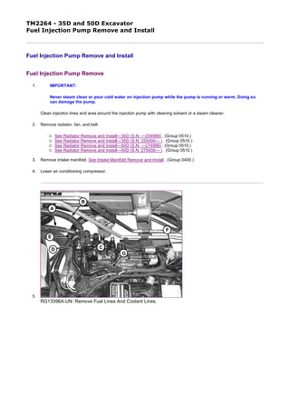
1. TM2264 - 35D and 50D Excavator
Fuel Injection Pump Remove and Install
Fuel Injection Pump Remove
1. IMPORTANT:
Never steam clean or pour cold water on injection pump while the pump is running or warm. Doing so
can damage the pump.
Clean injection lines and area around the injection pump with cleaning solvent or a steam cleaner.
2. Remove radiator, fan, and belt.
See Radiator Remove and Install—35D (S.N. —254999) . (Group 0510.)
See Radiator Remove and Install—35D (S.N. 255000— ) . (Group 0510.)
See Radiator Remove and Install—50D (S.N. —274999) . (Group 0510.)
See Radiator Remove and Install—50D (S.N. 275000— ) . (Group 0510.)
3. Remove intake manifold. See Intake Manifold Remove and Install . (Group 0400.)
4. Lower air conditioning compressor.
5.
RG13396A-UN: Remove Fuel Lines And Coolant Lines.
1/10
2019/11/19
file:///C:/ProgramData/Service%20ADVISOR/Temp/TM2264_09001faa802a...
2. RG13397A-UN: Injection Pump Gear Cover
RG13398A-UN: Injection Pump Gear Timing Marks
LEGEND:
A - Fuel Inlet Line
B - Fuel Return Line
C - Injector Return Line
D - Coolant Line
E - Coolant Line
F - Fuel Shutoff Solenoid Wire Connector
G - Foam Spacer
H - Cap Screw (4 used)
I - Pump Gear Timing Mark
J - Idler Gear Timing Mark
Disconnect fuel inlet line (A), fuel return line (B), and injector return line (C).
6. Disconnect coolant lines (D and E).
7. Disconnect fuel shutoff solenoid wire connector (F).
8. Remove foam spacer (G).
9. Remove cap screws (H) and remove injection pump gear access cover.
10. NOTE:
For all the timing marks to become aligned, engine may need to be rotated up to fifty-two times.
2/10
2019/11/19
file:///C:/ProgramData/Service%20ADVISOR/Temp/TM2264_09001faa802a...
3. Alignment marks (I and J) are both identified with a stamped letter “B”.
Rotate engine in the direction of rotation until mark (I) on pump gear aligns with mark on idler gear (J) (both identified
by a stamped letter B). Use chalk or paint to mark injection pump gear to idler gear.
11.
RG13399A-UN: Injection Pump Timing Gear
RG13400A-UN: Injection Pump Timing Gear Puller
3/10
2019/11/19
file:///C:/ProgramData/Service%20ADVISOR/Temp/TM2264_09001faa802a...
4. TX1062018A-UN: Injection Pump Timing Marks
LEGEND:
A - Timing Gear Nut and Washer
B - Cap Screw (4 used)
C - Threaded Puller Holes
D - Puller Cap Screw (2 used)
E - Gear Puller
F - Injection Pump Timing Mark
G - Gear Cover Mounting Plate Timing Mark
Remove gear retaining nut and washer (A).
12. IMPORTANT:
Do not loosen or disturb cap screws (B) securing gear to the hub. Gear to hub adjustment is pre-set to
comply with strict EPA emissions requirements and is not adjustable. This procedure is done at the
pump manufacturer and cannot be duplicated in the field.
Install puller (E) into threaded holes (C) on gear using cap screws (D).
13. IMPORTANT:
Engine must not be rotated when timing gear is removed from injection pump shaft. Engine should only
be rotated when timing gear is securely fastened to pump or engine damage could result.
Remove gear and hub assembly from injection pump shaft. Gear will stay inside timing cover.
14. IMPORTANT:
Marks must be made on the injection pump and the gear cover mounting plate to correctly install the
pump. If marks are not made, there will be no way to properly time the injection pump.
Note position of timing marks on gear cover mounting plate (G) and injection pump (F). Pump must be installed at the
exact same timing mark as when removed. Scribe a line as accurately and straight as possible at the pump flange
mark (F) onto the gear cover mounting plate.
4/10
2019/11/19
file:///C:/ProgramData/Service%20ADVISOR/Temp/TM2264_09001faa802a...
5. 15.
RG13402A-UN: Injection Pump Mounting Points
LEGEND:
A - External Lube Line
B - Cap Screw
C - Nut (3 used)
Remove external lube line (A) from pump.
16. Remove cap screw (B).
17. IMPORTANT:
Marks must be made on the injection pump and the gear cover mounting plate to properly install pump.
You must also record the injection pump timing number marked on the pump to correctly install the
pump. If marks are not made and the timing number not recorded, there will be no way to properly time
the injection pump.
Remove pump flange mounting nuts (C) and remove pump.
18. NOTE:
The injection pump timing number is stamped on the engine side of the fuel injection pump
housing. Treat this number as though there is a decimal point between the two digits. (Example 68
= 6.8).
Find and record pump timing number stamped on pump. This number will be needed if pump is being replaced or
recalibrated.
IMPORTANT:
DO NOT attempt to service the injection pump or governor. If unit is in need of repair, it must be serviced
by a qualified EPA/CARB certified fuel injection repair shop. If replacement is necessary, replace entire
unit. Do not rotate engine while injection pump is removed. If engine is rotated, the timing gear cover
must be removed to ensure correct timing.
Pump Installation
5/10
2019/11/19
file:///C:/ProgramData/Service%20ADVISOR/Temp/TM2264_09001faa802a...
6. 1.
RG13399A-UN: Injection Pump Timing Gear
LEGEND:
A - Timing Gear Nut and Washer
B - Cap Screw (4 used)
C - Threaded Puller Holes
Install new O-ring on injection pump.
2. Put injection pump onto back of gear cover mounting plate. Install three mounting nuts. Do not tighten. Align key on
shaft with keyway in gear hub. Ensure gear is still aligned to idler gear.
3. Install nut and washer (A) on pump shaft. Tighten nut to specification.
4.
TX1062057A-UN: Injection Pump Timing Marks
Item Measurement Specification
Fuel Injection Pump Drive Gear
Hub-to-Shaft Retaining Nut
Torque 78—88 N˙m
58—65 lb-ft
6/10
2019/11/19
file:///C:/ProgramData/Service%20ADVISOR/Temp/TM2264_09001faa802a...
7. RG13415A-UN: Injection Pump Mounting
LEGEND:
A - Injection Pump Timing Mark
B - Gear Cover Mounting Plate Timing Mark
C - Pump Mounting Nut (3 used)
D - Cap Screw
E - External Lube Line
Align timing mark on injection pump (A) with correct mark on gear cover mounting plate (B).
5. Tighten three pump mounting nuts (C) to specification.
6. Install cap screw (D). Tighten to specification.
7. Fill pump with engine oil through external lube line port until oil runs out. Install external lube line. Tighten lube line
fitting (E) to specification.
8. Install cover for injection pump timing gear.
Item Measurement Specification
Injection Pump Mounting Nuts Torque 26 N˙m
228 lb-in.
Item Measurement Specification
Injection Pump Mounting Cap
Screw
Torque 26 N˙m
228 lb-in.
Item Measurement Specification
Injection Pump External Lube Line
Fitting
Torque 15 N˙m
133 lb-in.
7/10
2019/11/19
file:///C:/ProgramData/Service%20ADVISOR/Temp/TM2264_09001faa802a...
8. 9.
RG13396A-UN: Install Fuel and Coolant Lines
LEGEND:
A - Fuel Inlet Line
B - Fuel Return Line
C - Injectors Return Line
D - Coolant Line
E - Coolant Line
F - Fuel Shutoff Solenoid Wire Connector
G - Foam Spacer
Install spacer (G) between pump and engine block.
10. Connect fuel shutoff solenoid wire connector (F).
11. Connect fuel lines (A, B, and C).
12. Connect coolant lines (D and E).
13. Install intake manifold. See Intake Manifold Remove and Install . (Group 0400.)
14. Install radiator, fan, and belt.
See Radiator Remove and Install—35D (S.N. —254999) . (Group 0510.)
See Radiator Remove and Install—35D (S.N. 255000— ) . (Group 0510.)
See Radiator Remove and Install—50D (S.N. —274999) . (Group 0510.)
See Radiator Remove and Install—50D (S.N. 275000— ) . (Group 0510.)
New, Rebuilt, or Recalibrated Pump Timing
8/10
2019/11/19
file:///C:/ProgramData/Service%20ADVISOR/Temp/TM2264_09001faa802a...
9. 1.
RG13614-UN: Injection Pump Sticker
LEGEND:
A - Middle 0° Line
B - 1° Line
C - 2° Line
D - 0.5° Line
Install timing mark sticker supplied with pump so that the (A) line is exactly in-line with the mark that was made on the
gear cover mounting plate when the pump was removed.
2. IMPORTANT:
Injection pump timing can not be performed without injection pump timing numbers from original and
replacement pumps. There is no way to properly install the injection pump without these numbers.
Calculate the difference between the timing numbers, recorded earlier, from the original and replacement/recalibrated
pumps. This calculated number will be needed to correctly time the pump.
Example: If the timing number on the replacement/recalibrated pump was 6.0, and the timing number on the original
pump is 4.0 (fuel injection angle of replacement/recalibrated pump) - (fuel injection angle of original pump), the
replacement pump should be timed at the +2.0° (advanced) mark (C) on the new timing mark sticker.
3. NOTE:
Rotating the injection pump away from the cylinder block will advance the timing and rotating the
injection pump toward the cylinder block will delay the timing.
Set the pump to the correct timing mark using the calculated number difference between the original and replacement
pumps. Adjust timing accordingly using the new timing mark sticker.
4. Hold the pump at the correct timing mark and tighten three pump mounting nuts and cap screw to specification.
9/10
2019/11/19
file:///C:/ProgramData/Service%20ADVISOR/Temp/TM2264_09001faa802a...
10. 5. If removed, install timing cover. See Timing Gear Cover Remove and Install . (Group 0400.)
6.
RG13396A-UN: Install Fuel And Coolant Lines
LEGEND:
A - Fuel Inlet Line
B - Fuel Return Line
C - Injectors Return Line
D - Coolant Line
E - Coolant Line
F - Fuel Shutoff Solenoid Wire Connector
G - Foam Spacer
Install spacer (G) between pump and engine block.
7. Connect fuel shutoff solenoid wire connector (F).
8. Connect fuel lines (A, B, and C).
9. Connect coolant lines (D and E).
10. Install intake manifold. See Intake Manifold Remove and Install . (Group 0400.)
11. Install radiator, fan, and belt.
See Radiator Remove and Install—35D (S.N. —254999) . (Group 0510.)
See Radiator Remove and Install—35D (S.N. 255000— ) . (Group 0510.)
See Radiator Remove and Install—50D (S.N. —274999) . (Group 0510.)
See Radiator Remove and Install—50D (S.N. 275000— ) . (Group 0510.)
Item Measurement Specification
Injection Pump Mounting Nuts Torque 26 N˙m
228 lb-in.
Injection Pump Mounting Cap
Screw
Torque 26 N˙m
228 lb-in.
OUO1030,00000CA-19-20090721
10/10
2019/11/19
file:///C:/ProgramData/Service%20ADVISOR/Temp/TM2264_09001faa802a...
11. TM2264 - 35D and 50D Excavator
Fuel Injection Nozzles Remove and Install
General Nozzle Service Precautions
Before removal, thoroughly remove all dirt from the cylinder head around fuel injection nozzles. Clean with compressed air to
prevent dirt from entering the cylinders. Plug the bore in the cylinder head after each nozzle has been removed. Cap fuel line
openings as soon as they are disconnected.
Immediately fit protective caps over the nozzle tips and the line connections to avoid handling damage and getting debris in
fuel system.
Do not bend the fuel delivery lines, as this may affect their durability. When loosening the fuel pressure lines, hold male union
of nozzle line stationary with a backup wrench.
1. IMPORTANT:
Never steam clean or pour cold water on injection pump while the pump is running or warm. Doing so
can damage the pump.
Clean the injection pump lines and area around the nozzles using a parts cleaning solvent or steam cleaner.
NOTE:
Nozzles are matched to the cylinders. If removing more than one nozzle, tag each nozzle,
according to the cylinder from which it was removed.
1/3
2019/11/19
file:///C:/ProgramData/Service%20ADVISOR/Temp/TM2264_09001faa802a...
12. 2.
RG13407-UN: Fuel Injector Components
LEGEND:
A - Cap Screw and Washer
B - Retaining Plate
C - Hose Clamp
D - Leak-Off Hose
E - Injection Nozzle
F - Ring
G - Heat Protector
Loosen fuel injection line connectors-to-nozzles slightly to release pressure in the fuel system.
3. Loosen line clamp(s) and remove fuel injection lines.
4. Remove clamps (C) and leak-off hoses (D).
5. Remove cap screw and washer (A) and retaining plate (B).
6. Remove injection nozzle (E), ring (F), and TEFLON ® heat protector (G). If ring and protector stay in cylinder head,
thread a cap screw into protector and pull from cylinder head.
2/3
2019/11/19
file:///C:/ProgramData/Service%20ADVISOR/Temp/TM2264_09001faa802a...
13. 7.
M82126A-UN: If Nozzles Stick in Cylinder Head
LEGEND:
A - Large Flat Washer
B - Nut (2 used)
C - Cap Screw
D - Old Injection Line Nut
E - Injection Nozzle
If nozzles are stuck in cylinder head:
Grind the head of a cap screw (C) so it fits inside a nut from an old injection line (D).
Use two nuts (B) to attach a large flat washer (A) to the cap screw.
Install assembly onto nozzle and use a puller and slide hammer to pull nozzle from cylinder head.
8. Test injection nozzles. Perform Fuel Injection Nozzle Check . (Group 9010-25.)
9. Installation is done in the reverse order of removal.
10. Tighten retaining plate nuts.
Item Measurement Specification
Fuel Injection Retaining Plate Cap
Screw
Torque 24—28 N˙m
212—248 lb-in
TEFLON is a trademark of Du Pont Co. OUO1030,00000CB-19-20051128
3/3
2019/11/19
file:///C:/ProgramData/Service%20ADVISOR/Temp/TM2264_09001faa802a...
14. TM2264 - 35D and 50D Excavator
Fuel Injection Nozzles Disassemble and Assemble
Fuel Injection Nozzles Disassemble
RG11097A-UN: Hole-Type Nozzle
LEGEND:
A - Injector Body
B - Shims
C - Spring
D - Spring Seat
E - Separator Plate
F - Nozzle Valve
G - Nozzle Body
H - Retaining Nut
I - Index Pin (2 used)
NOTE:
If servicing more than one nozzle, keep parts for each nozzle separate from one another.
1. Disassemble fuel injection nozzles.
1/5
2019/11/19
file:///C:/ProgramData/Service%20ADVISOR/Temp/TM2264_09001faa802a...
15. 2. IMPORTANT:
If injection nozzles are disassembled to be cleaned, the same number and thickness of shims must be
installed.
Clean and inspect nozzle components.
Fuel Injection Nozzles Clean and Inspect
2/5
2019/11/19
file:///C:/ProgramData/Service%20ADVISOR/Temp/TM2264_09001faa802a...
17. M82326B-UN: Nozzle Body, Separator Plate, Contact & Sealing Surfaces
LEGEND:
A - Injector Body
B - Fuel Return Pipe
C - Shims
D - Spring
E - Index Pin
F - Separator Plate
G - Nozzle Body
H - Nozzle Valve
I - Retaining Nut
J - Spring Seat
K - Nozzle Contact Surfaces
L - Sealing Surfaces
NOTE:
To clean nozzles properly, JDF13B Nozzle Cleaning Kit is recommended. The cleaning kit is available
through the John Deere SERVICEGARD ™ Catalog.
1. Remove anti-corrosive grease from new or reconditioned nozzles by washing them thoroughly in diesel fuel.
2. IMPORTANT:
Never use a steel brush to clean nozzles as this will distort the spray hole.
Remove carbon from used nozzles, and clean by washing in diesel fuel. If parts are coated with hardened carbon or
lacquer, it may be necessary to use a brass wire brush (supplied in nozzle cleaning kit).
3. After removing carbon or lacquer from the exterior of nozzle, inspect sealing surfaces between separator plate and
nozzle body for nicks or scratches.
4. Inspect condition of separator plate and nozzle body. Contact area of separator plate (both parts) must not be scored
or pitted. Use an inspection magnifier to aid in making the inspection.
5. Check nozzle contact surface on separator plate for wear. If contact surface is more than specification, replace nozzle
assembly.
6. Inspect the piston (large) part of nozzle valve to see that it is not scratched or scored and that lower (tip) end of valve
is not broken. If any of these conditions are present, replace the nozzle assembly.
Item Measurement Specification
Fuel Injection Nozzle Contact
Surface
Size 0.10 mm
0.0039 in.
4/5
2019/11/19
file:///C:/ProgramData/Service%20ADVISOR/Temp/TM2264_09001faa802a...
18. 7.
M35919-UN: Nozzle Valve & Body
LEGEND:
A - Nozzle Valve
B - Nozzle Body
Further inspect the nozzle assembly by performing a slide test. Use the following procedure:
a. Dip the nozzle valve in clean diesel fuel. Insert valve (A) in nozzle body (B).
b. Hold nozzle vertical, and pull valve out about 1/3 of its engaged length as shown.
c. Release valve. Valve should slide down to its seat by its own weight.
Replace nozzle assembly if the valve does not slide freely to its seat.
Fuel Injection Nozzles Assemble
1. Assembly is done in the reverse order of disassembly.
2. Tighten retaining nut (H) to specification.
3. After assembly is complete, test injection nozzle. Perform Fuel Injection Nozzle Check . (Group 9010-25.)
Item Measurement Specification
Fuel Injection Nozzle Retaining Nut Torque 43 N˙m
31 lb-ft
SERVICEGARD is a trademark of Deere & Company. OUO1030,00000CC-19-20051128
5/5
2019/11/19
file:///C:/ProgramData/Service%20ADVISOR/Temp/TM2264_09001faa802a...
19. TM2264 - 35D and 50D Excavator
Rocker Arm Cover Remove and Install
RG13393-UN: Rocker Arm Cover
LEGEND:
A - Special Nut (3 used)
B - Diaphragm Cover
C - Spring
D - Diaphragm
E - Oil Filler Cap
F - Gasket
G - Baffle
H - Baffle Plate
I - Gasket
J - Rocker Arm Cover
K - Crankcase Breather Tube
L - O-Ring
1/2
2019/11/19
file:///C:/ProgramData/Service%20ADVISOR/Temp/TM2264_09001faa802a...
20. M - Spring Plate
1. Remove the special nuts (A).
2. Disconnect crankcase breather tube (K).
3. Remove rocker arm cover (J) from cylinder head.
4. Remove diaphragm cover (B).
5. Remove and inspect spring (C) and diaphragm (D). Replace if damaged or deteriorated.
6. Remove baffle plate (H) and baffle (G).
7. Wash baffle in solvent and blow dry with compressed air. Replace baffle if it is damaged or deteriorated.
8. Install baffle and baffle plate.
9. Install diaphragm, spring plate (M), spring, and diaphragm cover.
10. Inspect gasket (I) and O-rings (L) before reinstalling rocker arm cover. Replace if damaged.
11. Clean cylinder head surface and install rocker arm cover on cylinder head. Install special nuts and tighten to
specification.
Item Measurement Specification
Rocker Arm Cover Special Nuts Torque 18 N˙m
156 lb-in.
OUO1030,000006C-19-20051128
2/2
2019/11/19
file:///C:/ProgramData/Service%20ADVISOR/Temp/TM2264_09001faa802a...
21. TM2264 - 35D and 50D Excavator
Rocker Arm Shaft Assembly Repair
Rocker Arm Shaft Disassemble
1.
RG13416-UN: Rocker Arm Shaft Assembly
LEGEND:
A - Nut
B - Adjusting Screw
C - Mounting Cap Screw
D - Nut
E - Stud
F - Rocker Arm End Support
G - Rocker Arm Shaft
H - Push Rod
I - Valve Cap
J - Intake Valve Rocker Arm
K - Exhaust Valve Rocker Arm
L - Mounting Cap Screw
M - Rocker Arm Shaft Spring
N - Rocker Arm Center Support
Remove rocker arm cover. See Rocker Arm Cover Remove and Install . (Group 0400.)
2. Remove rocker arm end support mounting cap screws (C).
3. Remove rocker arm center support mounting cap screws (L).
4. Lift rocker arm assembly from cylinder head and set on bench.
5. NOTE:
When disassembling the rocker arm assembly, replace components in same location on rocker arm shaft they were removed from.
Slide rocker arm assembly components off rocker arm shaft while noting positions for reassembly.
6. Lift push rods (H) from cylinder head and note order of removal for reassembly in same positions in head.
Rocker Arm Shaft Inspect
1.
M35262A-UN: Measure Rocker Arm Shaft Outer Diameter
1/3
2019/11/19
file:///C:/ProgramData/Service%20ADVISOR/Temp/TM2264_09001faa802a...
22. Thank you very much for
your reading. Please Click
Here. Then Get COMPLETE
MANUAL. NO WAITING
NOTE:
If there is no response to
click on the link above,
please download the PDF
document first and then
click on it.
23. M82022A-UN: Measuring Rocker Arm ID
LEGEND:
A - Rocker Arm Shaft
B - Rocker Arm
Measure outer diameter of rocker arm shaft (A) at each rocker arm location.
Replace rocker arm shaft if less than wear limit.
2. Measure inner diameters of rocker arms (B) and supports.
Replace rocker arms or supports if ID is more than wear limit.
3.
M82023A-UN: Measure Length and Bending of Push Rod
LEGEND:
A - Push Rod Length
B - Push Rod Bend
Measure length (A) and bending (B) of push rod.
Replace push rod if not within specifications.
Item Measurement Specification
Rocker Arm Shaft OD 15.97—15.98 mm
0.6286—0.6293 in.
Wear Limit 15.95 mm
0.6280 in.
Item Measurement Specification
Rocker Arm Shaft Support ID 16.00—16.02 mm
0.630—0.631 in.
Wear Limit 16.09 mm
0.633 in.
Rocker Arm Shaft-to-Rocker Arm
and Shaft Support Clearance
Wear Limit 0.14 mm
0.006 in.
Item Measurement Specification
Push Rod Length 178.2—178.75 mm
7.018—7.037 in.
Push Rod Bend Wear Limit 0.03 mm
0.001 in.
2/3
2019/11/19
file:///C:/ProgramData/Service%20ADVISOR/Temp/TM2264_09001faa802a...
24. Rocker Arm Shaft Assemble
1. NOTE:
Lubricate all parts with clean oil during assembly.
Install push rods in cylinder head with ball-shaped end down in head. Push rods should be in same locations they were removed from.
2. Assemble rocker arm assembly components in the reverse order of removal.
3. Place rocker arm assembly on cylinder head. Align rocker arms with valves and push rods. Align rocker arm end supports and center supports with corresponding holes in head.
4. Install rocker arm support mounting cap screws and torque to specification.
5. Adjust valve clearance. See Engine Valve Lash (Clearance) Check and Adjustment . (Group 9010-25.)
Item Measurement Specification
Rocker Arm Support Cap Screws Torque 26 N˙m
230 lb-in.
OUO1030,000006F-19-20060105
3/3
2019/11/19
file:///C:/ProgramData/Service%20ADVISOR/Temp/TM2264_09001faa802a...
25. TM2264 - 35D and 50D Excavator
Cylinder Head Remove and Install
Cylinder Head Remove
T207557-UN: Cylinder Head Remove and Install
1/8
2019/11/19
file:///C:/ProgramData/Service%20ADVISOR/Temp/TM2264_09001faa802a...