Downloaded 204 times
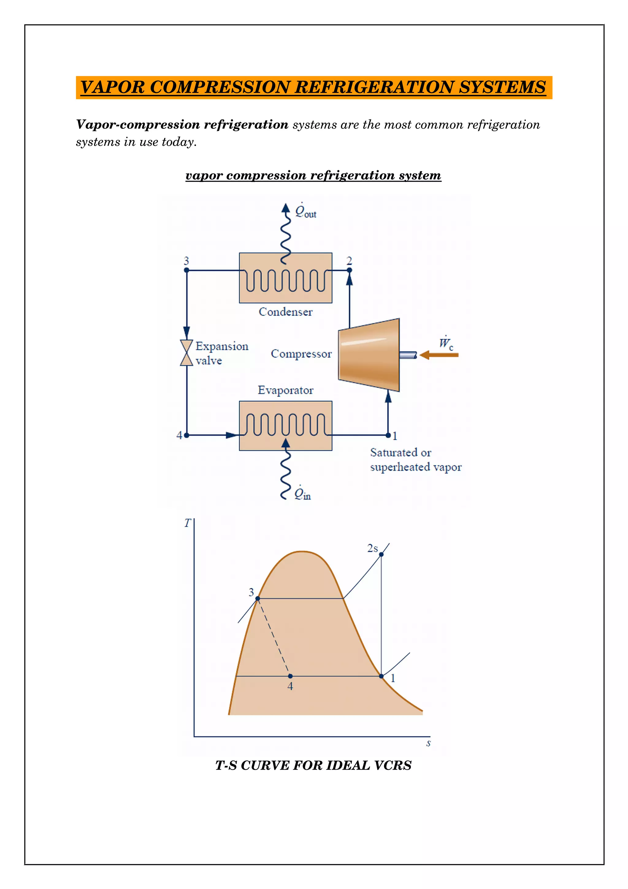
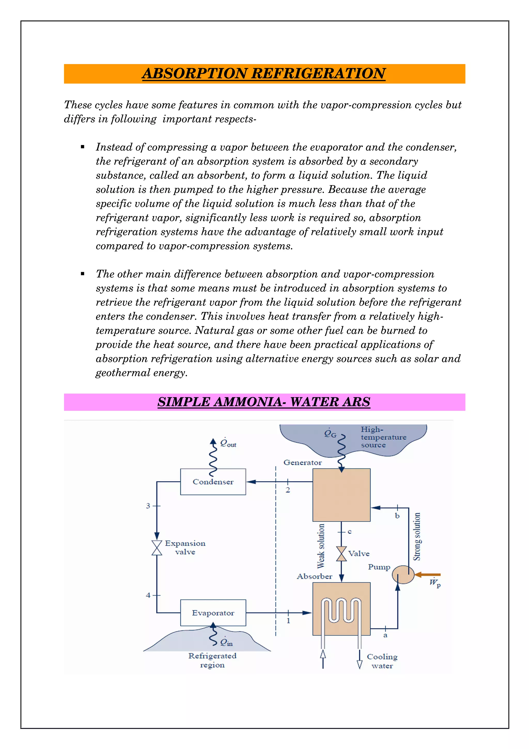
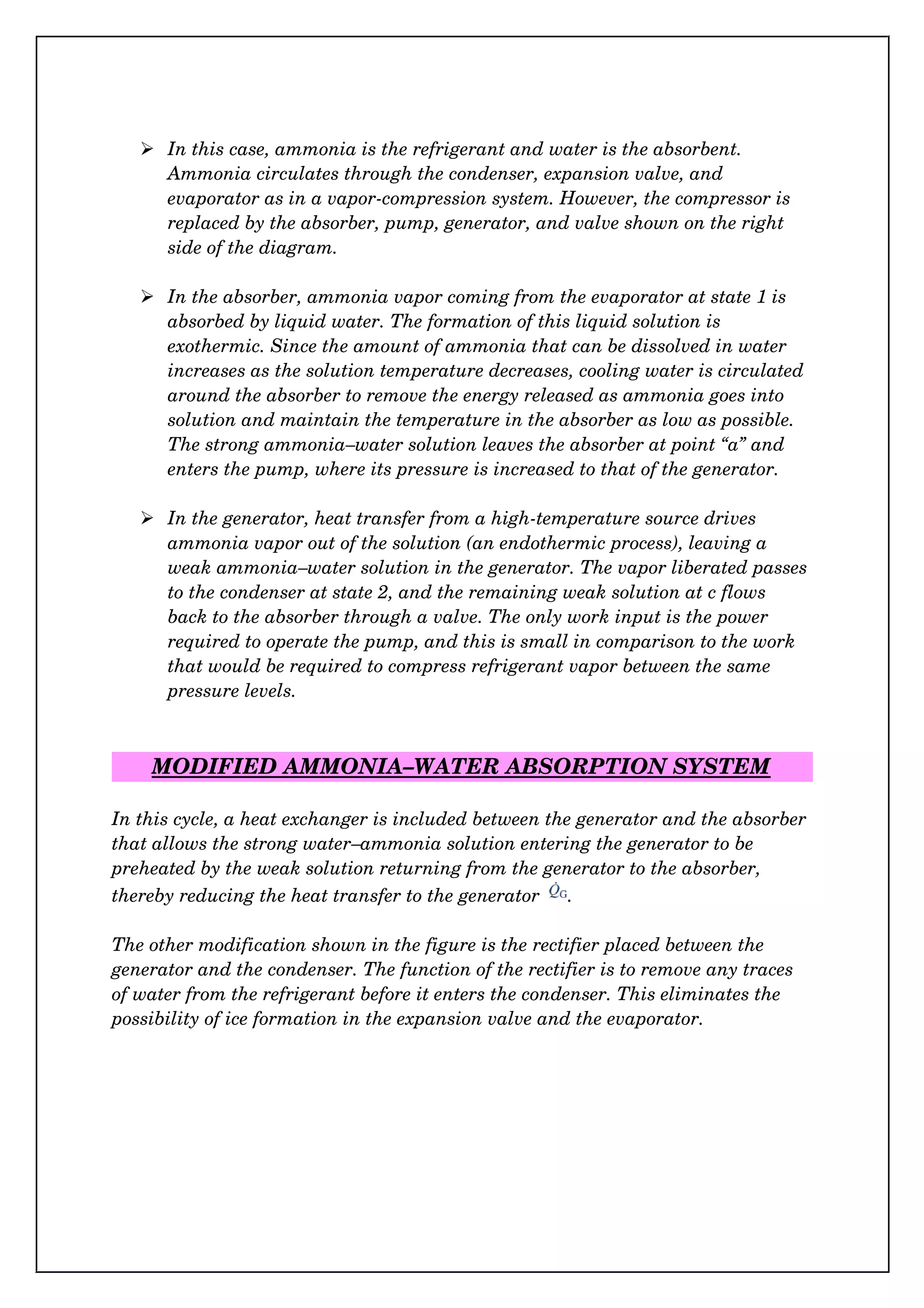
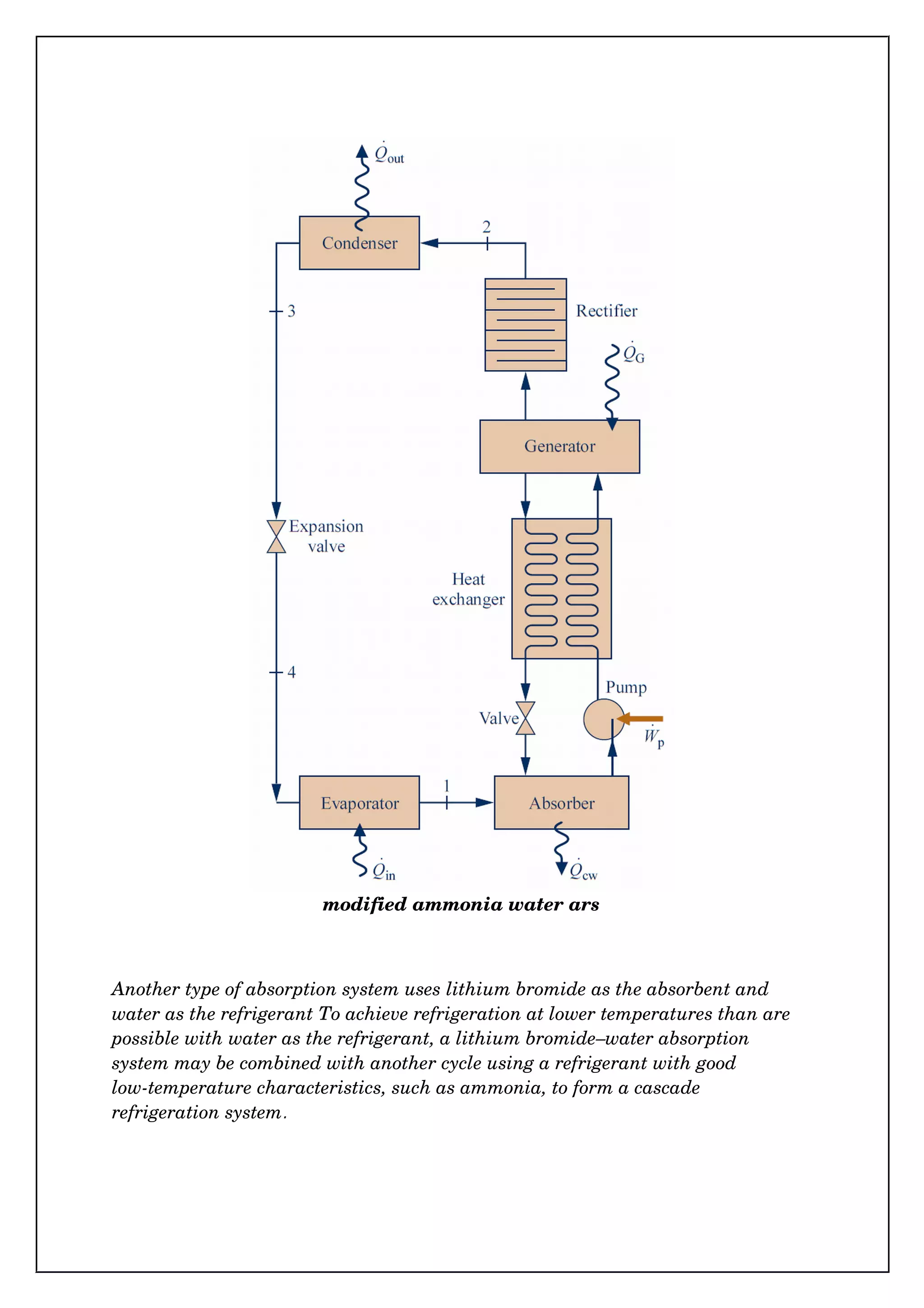

The document discusses refrigeration systems, including vapor refrigeration systems like the Carnot cycle and vapor compression refrigeration systems (VCRS). It also covers absorption refrigeration systems, which use a secondary substance called an absorbent to absorb the refrigerant into a liquid solution rather than compressing it. Absorption systems have lower work input compared to vapor compression. A common example is the ammonia-water absorption refrigeration system, which uses ammonia as the refrigerant and water as the absorbent.