
Recommended
More Related Content
Similar to Intel Harpertown ATCA Blade Prd Rev 1.4
Similar to Intel Harpertown ATCA Blade Prd Rev 1.4 (20)
Intel Harpertown ATCA Blade Prd Rev 1.4
- 1. Intel Dual Harpertown Quad-Core ATCA Server Node Board Product Requirements Document Revision 1.4 September 18, 2007 Sample systems engineering document authored by Jerry Viviano. I was given permission by Solectron to distribute this document after the project was cancelled. The cancellation occurred when Flextronics procured Solectron. Flextronics had only recently decided to cancel its own ATCA blade and chassis developments, as they decided that they did not want to continue in that line of work. I was the chief architect of this blade and the primary author of this document. However, parts of it were contributed to by a team of overseas Solectron engineers which was providing technical guidance to. This document can be freely distributed within the company to which I sent it for the purposes of assessing my skills in system engineering. It is not to be distributed outside of the company. A few things should be kept in mind when reviewing this document – 1) The document was in the midst of its genesis when its writing was discontinued. So there are some pieces which are not quite complete nor polished. 2) While I authored almost all of the document, a few parts were written by off-shore engineers I was working with. So some of the grammar is not quite up to snuff. Most of this content is in section 5. 3) Since the document is now disembodied from the Solectron server farm, the external links to files will naturally not work. Jerry Viviano
- 2. REQUIRED APPROVALS Michael Cowan Hardware Design Manager Sundra Raj BDC Site Head Barry Hutt Senior Director – Compute and Storage Segment PradipKumar Mandal Program Manager Chandrashekar DR Engineering Manager – Hardware Shrishail Halbhavi Project Lead – Software Vedantem Prasanth Program Lead Raleigh/Durham Team Members Department Name Hardware Design Michael Cowan, michaelcowan@solectron.com Engineering Frank Han, frankhan@solectron.com Jon McChristian, jonmcchristian@solectron.com Jerry Viviano, jerryviviano@solectron.com David Warren, davidwarren@solectron.com
- 3. Table of Contents Intel Dual Harpertown Quad-Core .........................1 ATCA Server Node Board.......................................1 Product Requirements Document .........................1 Revision 1.4.............................................................1 1 Introduction..........................................................10 1.1 Protection of Vendor Information.........................................................10 1.2 Scope.......................................................................................................10 1.3 Document Conventions/Navigating......................................................11 1.3.1 Hyperlinks...................................................................................................................................... 11 1.3.2 Section references......................................................................................................................... 11 1.3.3 Requirements Notation.................................................................................................................. 11 1.4 Terms and Abbreviations......................................................................12 1.5 Authors....................................................................................................14 1.6 Document History...................................................................................15 1.7 References..............................................................................................18 1.8 Known Shortcomings............................................................................18 2 Architectural Overview........................................19 2.1 Overview..................................................................................................19 2.2 General ATCA Conformance.................................................................19 2.3 Summary Hardware Feature List..........................................................20 2.4 Block Diagram.........................................................................................21 3 Main Hardware Functional Elements.................22 Document Type Document Identification Status Date Product TBD Sept 18, 2007 Requirement Project Author Page Document Intel Harpertown Blade Jerry Viviano 3 of 84
- 4. 3.1 Main Processor Subsystem...................................................................22 3.2 North Bridge - Memory Controller Hub................................................23 3.3 Memory Subsystem................................................................................23 3.4 South Bridge – ICH9/ICH9R...................................................................25 3.5 Super I/O Device.....................................................................................26 3.6 Real Time Clock......................................................................................26 3.7 BIOS Flash Configuration......................................................................26 3.8 Base Channel Interface..........................................................................26 3.9 Fabric Interface.......................................................................................27 3.10 Processor Thermal/Power Management ...........................................28 3.11 Power Supply Systems........................................................................28 3.11.1 Input Voltage Range.................................................................................................................... 29 3.11.2 Power Circuitry Topology.............................................................................................................29 3.11.3 Power Sequencing.......................................................................................................................31 3.11.4 Voltage Rail Current Requirements............................................................................................. 32 3.11.5 Power Consumption.................................................................................................................... 33 3.12 Board Health Monitoring Systems......................................................34 3.12.1 Thermal Sensors......................................................................................................................... 34 3.12.2 Power Supply Sensors and ADC Channel Assignments............................................................. 34 3.12.3 Platform Environmental Control Interface (PECI)........................................................................ 35 3.12.4 Payload Watch Dog Timer........................................................................................................... 35 3.12.5 IPMC Watch Dog Timer............................................................................................................... 35 3.13 Intelligent Platform Management Controller Requirements............35 3.14 Debug Capabilities/Support................................................................36 3.14.1 Payload Processor Physical Serial Ports..................................................................................... 36 3.14.2 IPMC serial port........................................................................................................................... 36 3.14.3 JTAG interface............................................................................................................................. 36 3.14.4 Intel XDP......................................................................................................................................37 3.14.5 Payload Reset Button.................................................................................................................. 37 3.14.6 IPMC Reset Button...................................................................................................................... 37 3.14.7 Chassisless Debug/Development Support.................................................................................. 38 3.14.8 Port 80 Support............................................................................................................................38 3.15 Component Placement.........................................................................38 Document Type Document Identification Status Date Product TBD Sept 18, 2007 Requirement Project Author Page Document Intel Harpertown Blade Jerry Viviano 4 of 84
- 5. 3.16 Front Panel ...........................................................................................39 3.16.1 Front Panel Connectors............................................................................................................... 39 3.16.2 Front Panel LEDs........................................................................................................................ 39 3.16.3 Barcode Product ID Label............................................................................................................ 40 3.17 SATA Hard Drive Option......................................................................41 3.18 Cross Interrupt Lines...........................................................................42 3.19 Back plane Connections......................................................................43 3.19.1 Zone 1..........................................................................................................................................43 3.19.2 Zone 2..........................................................................................................................................43 3.19.3 Zone 3..........................................................................................................................................43 4 Main Software Functional Elements..................44 4.1 Operating Systems.................................................................................44 4.2 IPMI...........................................................................................................44 4.3 Open IPMI................................................................................................44 4.4 Watch Dog Timer....................................................................................45 4.5 Payload Remote/Local Boot..................................................................45 4.6 Firmware Upgradeability........................................................................45 4.6.1 IPMC Firmware Upgrade............................................................................................................... 45 4.6.2 Payload BIOS Firmware Upgrade................................................................................................. 45 4.7 OS-Controlled Hardware Power Management.....................................46 4.8 Serial Over LAN (SOL)...........................................................................46 4.9 Virtualization Support............................................................................46 4.10 BIOS.......................................................................................................47 5 Detailed Software Requirements........................48 5.1 General Description...............................................................................48 5.1.1 System Perspective....................................................................................................................... 48 5.1.2 Assumptions on Availability of Various Development Tools/Components.................................... 50 5.1.3 Dependencies and Risks............................................................................................................... 50 5.1.4 Required Development Environment and Tools............................................................................ 51 5.2 External Interface Specifications..........................................................51 Document Type Document Identification Status Date Product TBD Sept 18, 2007 Requirement Project Author Page Document Intel Harpertown Blade Jerry Viviano 5 of 84
- 6. 5.2.1 User Interfaces.............................................................................................................................. 51 5.3 Functional Requirements......................................................................52 5.3.1 BIOS Functional Requirements..................................................................................................... 52 5.3.2 Linux Functional Requirements..................................................................................................... 57 5.3.3 General Linux Requirements......................................................................................................... 57 5.4 IPMI Firmware Requirements................................................................59 5.5 General ATCA Specification Software Conformance Requirements 63 5.6 Deliverables.............................................................................................64 6 Performance Requirements................................65 7 System Address Map...........................................66 8 Hardware Device Addresses..............................68 9 Reliability Requirements.....................................69 9.1 Blade Insertions......................................................................................69 9.2 CPU Insertions........................................................................................69 9.3 DIMM Insertions......................................................................................69 9.4 MTBF........................................................................................................69 10 Optional ATCA Subsystems.............................70 10.1 Advanced Mezzanine Cards (AMC)...................................................70 10.2 Rear Transition Modules (RTM).........................................................70 11 Mechanical Requirements................................71 11.1 General..................................................................................................71 11.2 Front Panel............................................................................................71 11.3 Improved Alignment Keying................................................................71 11.4 Front Board Cover................................................................................71 Document Type Document Identification Status Date Product TBD Sept 18, 2007 Requirement Project Author Page Document Intel Harpertown Blade Jerry Viviano 6 of 84
- 7. 12 DFx Requirements.............................................72 13 Regulatory Compliance Requirements...........73 13.1 RoHS Requirements.............................................................................74 14 Risks....................................................................75 14.1 Scarcity of Marketing Input.................................................................75 14.2 San Clemente Schedule.......................................................................75 14.3 Thermal Issues.....................................................................................75 14.4 Lack of Intel Support............................................................................75 14.5 Lack Of A Budget.................................................................................75 14.6 Late Engagement with BIOS Vendor..................................................76 15 Bill Of Materials..................................................77 16 Requirements Conformance Matrix.................78 Document Type Document Identification Status Date Product TBD Sept 18, 2007 Requirement Project Author Page Document Intel Harpertown Blade Jerry Viviano 7 of 84
- 8. Tables Table 1: Summary Hardware Feature list.............20 Table 2 Supported Processors..............................22 Table 3 Differences Between ICH9 and ICH9R....25 Table 4 Power Sequencing Timing Parameters...31 Table 5 Voltage Rail Current Requirements.........32 Table 6: Power Consumption................................33 Table 7 ADC-Monitored Power Supply Signals...35 Table 8 Front Panel LED Definitions.....................40 Table 9 IPMI Action Handler Actions Per Event. .58 Table 10 Required Regulatory Standard Compliances............................................................74 Table 11 Intel Blade Draft Bill Of Material (BOM).77 Figures Figure 1 Navigation Toolbar.................................11 Figure 2 System Hardware Block Diagram..........21 Figure 3 Memory/Memory Controller Interface Topology..................................................................24 Figure 4 Allowable Memory Configurations.......25 Document Type Document Identification Status Date Product TBD Sept 18, 2007 Requirement Project Author Page Document Intel Harpertown Blade Jerry Viviano 8 of 84
- 9. Figure 5 8-Node Dual Star Fabric Topology........28 Figure 6 Power Circuitry Topology.......................30 Figure 7 Power Circuitry Sequencing...................31 Figure 8 Flexible JTAG Chaining Topology........37 Figure 9 Port 80 Debug Support...........................38 Figure 10 Initial Component Placement Proposal ..................................................................................39 Figure 11 Front Panel Elements Placement.........41 Figure 12 SATA Connectors..................................42 Figure 13 Software Architecture Block Diagram. 49 Figure 14 System Initialization Block Diagram...53 Figure 15 San Clemente System Address Map. . .67 Document Type Document Identification Status Date Product TBD Sept 18, 2007 Requirement Project Author Page Document Intel Harpertown Blade Jerry Viviano 9 of 84
- 10. Intel Harpertown ATCA Blade Product Requirements Document Page 10 of 84 1 Introduction The purpose of this document is to define the general features and requirements to be implemented in the Intel Dual Harpertown quad-core ATCA Processing Server Node blade project, hereafter referred to as the “Intel Harpertown blade”, what critical hardware and software elements will be used to implement the requirements, how they will be interconnected, and to a degree, what functions they will perform and how. In the interest of brevity, the term ‘ATCA’ will generally be used throughout this document to represent the more complete “AdvancedTCA” or “PICMG ATCA”. The Intel Harpertown blade will function as a compute server node blade in an Advanced TCA industry standard chassis, according to 1.7. There are numerous backplane protocols to choose from while still being within the bounds of compliance with the ATCA definition. In particular, The Intel Harpertown blade will utilize the Ethernet protocol across the backplane fabric as define in 1.7 as opposed to Serial RapidIO, PCI-Express, or any other ATCA-defined backplane protocol. It should be noted that the goal of the Intel Harpertown blade project will not specifically be to produce a specific salable item. Rather, it is to produce a reference design which can be easily tailored to Solectron’s potential customers’ needs. As such, in some respects, the design could be considered to be a bit ‘overkill’. For example, the current plan is for the design to support up to 48 GBytes of DDR2 memory. If a customer would prefer to save costs by limiting their specific design variant to only 16 or 32 GBytes, the design should easily be modified to that reduced requirement. • To avoid damage to the document template, do not add, change or remove formats. 1.1 Protection of Vendor Information Under NDA guidelines agreed to with Intel, Solectron is bound to protect the usage of certain code names used within this document. The following terms: • Harpertown • Bensley • Cranberry Lake • San Clemente by our agreements with Intel are strictly forbidden from being discussed or disseminated outside of Solectron, or even within Solectron with individuals who do not have a legitimate ‘need to know’. Intel considers unauthorized dissemination of these terms to be dangerous to their competitive advantage. Inappropriate use of these terms by Solectron could result in our being cutoff from critical design documents and support pertaining to the advanced information associated with the devices on which The Intel Harpertown blade is based. It is to Solectron’s competitive advantage to continue receiving this type of support from Intel. 1.2 Scope This product requirements document (PRD) defines the electrical, mechanical, environmental, and functional specification for a high performance Dual Intel Harpertown processor based single board computer built according the Advanced Telecom Computing Architecture (ATCA) specification. Architecturally, this document fits between the marketing requirements document (MRD) which calls out the general large-scale functional requirements of the product, and the hardware design specification and software design Document Type Document Identification Status Date Product TBD Sept 18, 2007 Requirement Project Author Page Document Intel Harpertown Blade Jerry Viviano 10 of 84
- 11. Intel Harpertown ATCA Blade Product Requirements Document Page 11 of 84 specification (HDS & SDS) with each respectively explain the detailed implementation plan and requirements for their respective parts of the blade. This PRD also fits between the MRD and HDS/SDS levels of planning chronologically as well. That is, the PRD takes the initial general hardware and software requirements from the finished MRD, and breaks them down into more specific approaches to be implemented in hardware and software. After the PRD is completed, it is then handed to the software and hardware teams as input into their respective detailed design documents, the SDS and HDS respectively. 1.3 Document Conventions/Navigating Navigation of this document may be made easier by viewing it in the Document Map mode. This yields an outline of the section headers along the left hand edge of the viewing window. The reader can click on a section header to immediately jump to the section. The control for enabling/disabling Document Map mode is at the first level of the View menu. 1.3.1 Hyperlinks Items highlighted in blue are hyperlinks to either other parts of this document, or to actual outside documents. Due to the limitations of the Solectron networking architecture, hyperlinks to external documents may not work from locations outside of the RTP facility. When a hyperlink is used to jump to another part of the document, a toolbar as shown in Figure 1 will appear. This can be used to immediately jump back to the hyperlink source location. This can be tried by simply clicking on the above reference to Figure 1. Figure 1 Navigation Toolbar 1.3.2 Section references The § symbol implies section. It is used to refer to sections in this document as well as sections in other documents 1.3.3 Requirements Notation Definite requirements specified in this document will be prefaced with a short category prefix, followed by an underscore, followed by a number, and then a colon. Both integer and decimal numbers are allowed, similar to the Dewey Decimal system. Two example requirements are: ARC_1: The Intel Harpertown blade will be an intelligent compute server node board utilizing dual Intel quad-core Harpertown 45 nm processors for a total of 8 processing cores. MEM_3: The system will support from 1 to 6 DIMMs, maximum of 3 DIMMs per channel subject to the San Clemente limitation of 6 ranks per channel. Document Type Document Identification Status Date Product TBD Sept 18, 2007 Requirement Project Author Page Document Intel Harpertown Blade Jerry Viviano 11 of 84
- 12. Intel Harpertown ATCA Blade Product Requirements Document Page 12 of 84 1.4 Terms and Abbreviations Term Description § Section (in this or other document) as in § 3.1.2 [N] External document reference ‘N’ ACPI Advanced Controlled Power Interface API Application Programmer’s Interface APIC Advanced Programmable Interrupt Controller AdvancedTCA Advanced Telecom Computing Architecture AMC Advanced Mezzanine Card AMI American Megatrends, Inc. ATCA Advanced Telecom Computing Architecture BIOS Basic Input Output System BOOTP Boot Protocol BSP Boot Strap Processor CRB Configuration Reference Board DDR Double Data Rate DHCP Dynamic Host Control Protocol DIMM Dual In-line Memory Module DMTF Distributed Management Task Force FSB Front Side Bus Gb Gigabit(s) GB Gigabyte(s) GbE Gigabit Ethernet Gbps Gigabit(s) Per Second GBps Gigabyte(s) Per Second HDS Hardware Design Specification HPM Hardware Platform Management I2C, or I2C Inter Integrated Chip (Bus) ICH I/O Controller Hub, AKA South bridge IPI Inter processor Interrupt IPMB Intelligent Platform Management Bus IPMC Intelligent Platform Management Controller IPMI Intelligent Platform Management Interface KCS Keyboard Control System KCS is a system that runs over the LPC bus between the IPMC and payload. It is the basic protocol that is used to communicate back and forth between the IPMC and payload. LFM Linear Feed per Minute LPC Low Pin Count LSP Linux Support Package MCH Memory Controller Hub, AKA North bridge MP Multi Processor MRD Marketing Requirements Document MTBF Mean Time Between Failures MTD Memory Technology Device NBP Network Boot Protocol NEBS Network Equipment Building System OS Operating System Payload In compute server domains, refers to the board’s main compute system. In this case, the payload would be the combination of the Intel Harpertown processors, the MCH and ICH. PCI Peripheral Component Interconnect PCI-E PCI Express PCISIG PCI Special Interest Group Document Type Document Identification Status Date Product TBD Sept 18, 2007 Requirement Project Author Page Document Intel Harpertown Blade Jerry Viviano 12 of 84
- 13. Intel Harpertown ATCA Blade Product Requirements Document Page 13 of 84 Term Description § Section (in this or other document) as in § 3.1.2 [N] External document reference ‘N’ ACPI Advanced Controlled Power Interface API Application Programmer’s Interface PECI Platform Environment Control Interface – A proprietary one-wire bus interface that provides a communication channel between the Intel processor and external thermal monitoring devices, for use in fan speed control. PECI communicates readings from the processor’s digital thermometer. PECI replaces the thermal diode available in previous processors. PICMG PCI Industrial Computer Manufacturers Group PMC PCI Mezzanine card POST Power-On Self-Test POST Power On Self Test PPS Pigeon Point Systems PXE Preboot eXecution Environment RDIMM Registered Dual In-line Memory Module RPM Red Hat Package Manager RTC Real Time Clock RTM Rear Transition Module SDR Sensor Data Record SDS Software Design Specification. ShMC Shelf Management Controller SIPI Startup IPI SMI System Management Interface SMP Symmetric Multi Processor SPD Serial Presence Data TBD To Be Decided TDP Thermal Design Power, also Total Dissipated Power TFTP Trivial File Transfer Protocol VID Voltage ID VLP Very Low Profile VPD Vital Product Data VRM Voltage Regulator Module Document Type Document Identification Status Date Product TBD Sept 18, 2007 Requirement Project Author Page Document Intel Harpertown Blade Jerry Viviano 13 of 84
- 14. Intel Harpertown ATCA Blade Product Requirements Document Page 14 of 84 1.5 Authors Department Name Tel. E-Mail Design and Engineering Jerry Viviano 919-998-4801 jerryviviano@solectron.com Prime Editor Design and Engineering Shreekanth Hiremath 0091 80 41151798 shrekanthHiremath@solectron.com Design and Engineering Jayanta Nath 0091 80 41151798 JayantaKumar@solectron.com Contributor Design and Engineering Gopal Jahagirdar 0091 80 41151798 GopalJahagirdar@solectton.com Contributor Design and Engineering Shrishail Halbhavi 0091 80 41151798 shrishailhalbhavi@solectron.com Contributor Document Type Document Identification Status Date Product TBD Sept 18, 2007 Requirement Project Author Page Document Intel Harpertown Blade Jerry Viviano 14 of 84
- 15. Intel Harpertown ATCA Blade Product Requirements Document Page 15 of 84 1.6 Document History Rev. Date Author Change History and Comments 1.0 July 25, J. Viviano First official revision based on AA.1 and group feedback. 2007 Numbered requirements Added DFX section Expaneded on Debug ports section. Specified exact processor model numbers. Updated block diagram Resolved issues on redundant boot flashes. Changed from 8 to 6 DIMMs. Max six DIMM changed from 8 to 4 GBytes. Added Super I/O info. Cleared up issues with Watch Dog Timers. Added SATA hard drive requirement. Removed 1 Gbps requirement. Specified Red Hat kernel revision. 1.1 Aug 9, J.Viviano Filled in sections on IPMC and BIOS firmware upgrade. 2007 Corrected Base interface Zone specifier to Zone 2. Addition of Port 80 debug support. Additional illustration on allowable memory configurations. Added Serial Over LAN content. Clarification of maximum memory to 48 GBytes, when/if 8 GByte DIMMs arrive. Added `Known Compliancy Issues’ column to regulatory requirements document list.. Additional OS-Controlled HW power management requirement ACPI. Power supply requirements added. SOL requirements updated. Added RoHS ref. & requirement. Removed reference to using PCI-E as update channel. Updated approvers & authors lists. Updated scope to reference HDS & SRS Added PRD Requirements Conformace Matrix. Added Risks section. Added Virtualization support section. Component placement map added. BOM Updated Tehuti references removed. Changed to Broadcom 57710 and Intel 82598 1.2 Aug 24, J. Viviano Renamed Approvers’ titles to those in the Roles and Responsibilities document. 2007 Updated block diagram. Document Type Document Identification Status Date Product TBD Sept 18, 2007 Requirement Project Author Page Document Intel Harpertown Blade Jerry Viviano 15 of 84
- 16. Intel Harpertown ATCA Blade Product Requirements Document Page 16 of 84 Rev. Date Author Change History and Comments Minor editorial changes. Added risks: Lack Of A Budget & Late Engagement with BIOS Vendor Detailed PWR_4 rqmt to spec upper limit at 230 Watts. Significantly reduced voltage and current monitoring requirements. Added BIOS requirements. Detailed BX, BX4, KX, KX4 requirements. Consolidated SATA option requirement into SATA_1, removing DBG_9. Clarified wording. Reduced Footer Size Added reasons for not requiring RTM inclusion. Added document conventions section. Clarified 50 Watt/ 80 Watt TDP text. Added JTAG chaining topology. Added dual-star requirement. Added DIMMs/Sockets gold surfaces. Changed from VMware Infrastructure 3 to VMWare Server virtualization software. More details on the front panel LEDs. Added table of all known possible processors. Discussed San Clemente and ICH9R internal temperature sensors. Added text on front panel LEDs functionality and colors. Added mechanical drawing of front panel elements placements. Enhanced BOM format to segregate costs of base board, memory, processor section, IPMC, debug sections. Removed Logic Analyzer interface requirement. Separated JTAG chain into separate payload and IPMC sections. 1.3 Sept 14, J. Viviano Changed block diagram to Intel 82598 instead of Tehuti. 2007 Changed block diagram to have only one optional SATA drive instead of two. Changed block diagram to have RTC in ICH9 instead of Super I/O Updated block diagram to include new 1600 MTps FSB Harpertown variants. Cleaned up wording on HLTH_9 payload WDT. Cleaned up wording of IPMC_2, eliminating bootloader redundancy. Cleaned up FWUG_ requirements, eliminating boootloader failsafe statement. Upgraded block diagram to Intel 82598, RTC in ICH9R Noted that the cross-interrupt lines will be separate from the IPMC-to-Payload SMI. Added SATA_2 & SATA_3 requirements. Added SATA connector type specifications. Changed firmware upgrade to waive bootloader upgrade failsafe requirement. Changed card insertion/extraction cycles to 250 min. Added justification of 24 GByte memory load, Equation 1. Added PTPM_4 Dynamically adjusted processor speeds. Added suggestion that all serial ports be accessible through modified faceplate. Document Type Document Identification Status Date Product TBD Sept 18, 2007 Requirement Project Author Page Document Intel Harpertown Blade Jerry Viviano 16 of 84
- 17. Intel Harpertown ATCA Blade Product Requirements Document Page 17 of 84 Rev. Date Author Change History and Comments Removed references to BCM57710. Added significant content to the performance requirements section. Changed MontaVista Linux to Red Hat Linux as OS. Clarification added on Front Side Bus speed control Super I/O changed from 87427 to 83627 Merged in Software Requirements Document Added requirement HLTH_2.5, which specifies that the ICH9/ICH9R internal temperature sensor will be monitored. Added description of PECI information flow. Added a section describing the ICH9/ICH9R south bridge. Added requirement SB_1 which specifies that the system will accommodate both the ICH9 and ICH9R south bridge devices. Added power circuitry topology map and power sequencing timing info. Rewrote section on voltage and current monitoring. Consolidated all power system information and requirements into a single section. Added table of voltage supply rails with voltage tolerances and max currents. Updated Virtualization requirements to one OS instance per core minimum. Removed references to VMware Server in detailed software requirements. Changed thremal sensor connection to IPMC to exclusively I2C. Updated the bill of materials. 1.4 Sept 18, J. Viviano Fixed the accidental omission of the SRS section 4.3, IPMI Functional 2007 Requirements Document Type Document Identification Status Date Product TBD Sept 18, 2007 Requirement Project Author Page Document Intel Harpertown Blade Jerry Viviano 17 of 84
- 18. Intel Harpertown ATCA Blade Product Requirements Document Page 18 of 84 1.7 References [1] PICMG® 3.0 Revision 2.0 AdvancedTCA® Base Specification® [2] PICMG® 3.1 Revision 1.0 Specification Ethernet/Fibre Channel for AdvancedTCA™ Systems [3] PICMG 3.0 Short Form Specification [4] Voltage Regulator Module (VRM) and Enterprise Voltage Regulator-Down (EVRD) 11.0 [5] San Clemente Memory Controller Hub Chipset EDS Rev 1.2 [6] Intelligent Platform Management Interface Specification Second Generation v2.0, Feb 12, 2004 [7] Intelligent Platform Management Interface Second Generation Specification v2.0, revision 1.0 Intelligent Platform Management Interface Specification v1.5, revision 1.1 Addendum Document Revision 3 Feb 15, 2006 [8] HPM.1 Hardware Platform Management IPM Controller Firmware Upgrade Specification [9] Debug Port Design Guide for UP/DP Systems [10] Solectron CORSDC-10-100059 DFX Design Guidelines for Rigid Printed Boards and Assemblies [11] Solectron CORSDC-10-100110.pdf Solectron Global Testability Design Guidelines [12] Intel based ATCA Compute Node Marketing Requirements Document (MRD) [13] Advanced Configuration and Power Interface Specification [14] Intel ATCA MRD 16Jul07 Rev 1 (2).xls [15] Intel Multiprocessor specification [16] Intel Software developer manual (3A & 3B) [17] Intelligent Platform Management Interface Specification v1.5 [18] Intelligent Platform Management Bus Communications Protocol Specification V1.0 [19] IPMB Address Allocation Specification v1 [20] Platform Management FRU Information Storage Definition v1.0 [21] VMWare’s “Virtual Machine Guide” (VMWare Server 1.0) [22] Harpertown Processor Electrical, Mechanical, and Thermal Specification (EMTS) Rev 1.25 [23] San Clemente MCH Chipset External Design Specification (EDS) Addendum Rev 1.2 [24] Intel I/O Controller Hub 9 (ICH9) Family Datasheet Intel Document Number 316972-001 [25] DIRECTIVE 2002/95/EC OF THE EUROPEAN PARLIAMENT AND OF THE COUNCIL of 27 January 2003 on the restriction of the use of certain hazardous substances in electrical and electronic equipment. 1.8 Known Shortcomings Section Topic Plan 13 Reliability requirements document unresolved Is not critical at this time. An MTBF is specified in this document in § 9.4 . Virtualization requirements still not defined Team will research this further and will come sufficiently. to a better understanding as to what the requirement really is. Document Type Document Identification Status Date Product TBD Sept 18, 2007 Requirement Project Author Page Document Intel Harpertown Blade Jerry Viviano 18 of 84
- 19. Intel Harpertown ATCA Blade Product Requirements Document Page 19 of 84 2 Architectural Overview 2.1 Overview ARC_1: The Intel Harpertown blade will be an intelligent compute server node board utilizing dual Intel quad- core Harpertown 45 nm processors for a total of 8 processing cores. ARC_2: The processor and chipset complement will be based on the Intel Cranberry Lake architecture, tailored to high density compute-server attributes. ARC_3: The board will be compliant with the PICMG 3.0 ATCA (Advanced Telecom Computing Architecture) Rev 2.0 standard, as well as PICMG 3.1 Rev 1.0 Ethernet/Fibre Channel for AdvancedTCA Systems. The Intel Harpertown blade will be a single-slot single-board compute server that offers a powerful control plane processing complex, dual Gigabit Ethernet ports for the base interface and dual 10 or 1 Gigabit Ethernet for the fabric interfaces. Other critical hardware components comprising the heart of the system include the Intel San Clemente Memory Hub Controller (MCH) A.K.A north bridge, ICH9/ICH9R I/O Controller Hub (ICH) A.K.A south bridge, Intel 82598 Dual XAUI fabric interface, and Renesas 2166 as the Intelligent Platform Management Controller (IPMC). The initial release of the board will support Red Hat Linux, but is expected to eventually offer several operating systems, including variants of Windows, UNIX, and Linux. ARC_4: The Intel Harpertown blade will provide system management capabilities and will be hot swap compatible per the ATCA specification. The power and flexibility of the design make it ideally suited for the telecom and datacomm markets. 2.2 General ATCA Conformance ARC_5: The Intel Harpertown blade will be conformant in all manners to PICMG ATCA spec 1.7 and the PICMG ATCA 10 Gbps Ethernet backplane spec 1.7. These documents specify minimum electrical, mechanical, thermal, and functional requirements of any system claiming to be ATCA compliant, specifically utilizing Ethernet as the backplane fabric interface. Since the PICMG ATCA specs cover these items in great detail, this document will generally only repeat requirements from the documents for clarity when necessary. The ATCA spec allows for a variety of backplane topologies, ranging from the simplest allowable form, the dual star, to the most comprehensive form which is complete mesh. ARC_6: The Intel Harpertown blade will be tailored to be a compute node in a dual star configuration, requiring only two backplane fabric interconnections, one to each of the two hubs. As such, it will not be expected to be able to take full advantage of a dual-dual star configuration or a full mesh configuration. Document Type Document Identification Status Date Product TBD Sept 18, 2007 Requirement Project Author Page Document Intel Harpertown Blade Jerry Viviano 19 of 84
- 20. Intel Harpertown ATCA Blade Product Requirements Document Page 20 of 84 2.3 Summary Hardware Feature List FEATURE FEATURE DESCRIPTION HOST CPUs Quad core 64 bit Xeon processors Two Quad-core 12 MByte L2 Cache per dual-core processor Intel Harpertown Intel PECI Thermal monitoring system. Xeon Processors Enhanced Intel SpeedStep Technology. Processor FSB interface interconnection speed of 1333 MTps, 10.6 GBps 333/400 MHz Clk, 80 Watt TDP board quad-pumped to 1333/1600 MTps. design. See processor list in § 3.1 . Chipset Dual independent processor interfaces interconnection with speeds of up to1333 MTps, 10.6 Intel 5100 GBps per processor interface. San Clemente Four x4 PCI Express interfaces configurable into various combinations of x4, x8, and x16, 250 Memory Hub MBps per lane. Controller (MHC) Memory interface - 144 bit, 266/333 MHz, 533/667 MTps, synchronous registered DDR2 North bridge controller interface with ECC. One Serial Peripheral Interconnect (SPI) port. 3 SMBus’s– Serial Presence Data (Master), Config (Slave), and GPIO (Master) interface. Intel ICH9 or 2 GBps Enterprise South bridge Interface (ESI) to 5100. ICH9R Six x1 PCI-E interfaces for general purpose use. I/O Controller South bridge One 10/100/1000-Base-T MAC internal. One Low Pin Count (LPC) interface used for communication with the IPMC. ICH9 or ICH9R Memory Up to 48 GByte 533/667 MHz DDR-2 ECC memory. Up to 6 DIMMs split into 2 channels. Boot-flash Two 2MB flash memory implemented as primary and secondary boot Base & Fabric Two 1000BASE-T connections to the ATCA base interface via magnetics. Interface Two 10 Gbps Ethernet XAUI ports connected to the ATCA backplane fabric interface. These ports are also 1 Gbps capable for compatibility with a vast array of legacy products. Update Channel The Intel Harpertown blade will not require an update channel as update channels are optional according to the PICMG specification 1.7. Board Renesas H8S2166 16-bit uController. 512 KByte internal flash, redundant boot sectors, six Management I2C interfaces, one LPC port, 8 internal 10-bit ADC channels. Controller (IPMC) RTC Real time clock, battery backed. Form Factor Single slot ATCA form factor (280mm x 322mm) RTM The initial offering of the Intel Harpertown blade will not support RTM. Reasons for this are detailed in § 10.2 . Table 1: Summary Hardware Feature list Document Type Document Identification Status Date Product TBD Sept 18, 2007 Requirement Project Author Page Document Intel Harpertown Blade Jerry Viviano 20 of 84
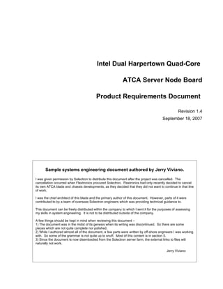
- 21. Intel Harpertown ATCA Blade Product Requirements Document Page 21 of 84 2.4 Block Diagram Registered DDR2 72-bit ECC, 240 Pin DIMMs Intel Dual Harpertown ATCA Block Diagram 533/667 MHz. Max 6 DIMMS 6 Ranks 24 GB Max w/ 4 GB Dual Rank DIMMs DIMM 2 CHN 1 - 533 & 677 MTPS Solectron Confidential. For Internal Use Only 48 GB Max w/ 8 GB Dual Rank DIMMs DIMM 2 CHN 0 - 533 & 677 MTPS DIMM 1 CHN 1 - 533 & 677 MTPS RTP to Perform SI Analysis on All High Rear Trans. Module DIMM 1 CHN 0 - 533 & 677 MTPS Speed Buses – DDR2, CPU/MCH, PCI-E, B A C K P L A N E DIMM 0 CHN 1 - 533 & 677 MTPS XAUI, 1GbE, etc . DIMM 0 CHN 0 - 533 & 677 MTPS ECC Chn 1 ECC Chn 0 266/333 MHz Red Dashed Outlines Imply Debug Only Load Intel Harpertown Proc 0 Serial 533/667 MTps x8 PCI-E 16 Gbps FD Presence Data Core 0 Core 2 SMBus 4.3/5.3 GBps Per Chnl XDP1 8.6/10.6 GBps Total Opt SATA x8 PCI-E PCI- 16 Gbps FD FSB0 E Primary Core 1 Core 3 North Bridge 6 7 Segment Flash BIOS Decoder (MCH) Fabric SATA For Port 80 PCI-Express Secondary to 2-Port XAUI ESI 2 GB/s 5100 Lgcl PCI Bus 0 LPC LPC Flash BIOS XAUI Switch XDP0 Intel 82598 San Clemente South Bridge XAUI PECI Core 0 Core 2 B0 Stepping (ICH) UART UART ICH9 or ICH9R Winbond XEON 0 FSB1 PECI Debug Port Core 1 Core 3 RTC 83627 Update Chnl PCI- XEON 1 I2C 12 PCI-E Super I/O Debug Port E I2C USB 2.0 6 x1 Intel Harpertown Proc 1 CFG SMBus Each Front Side Bus PECI- I2C EE- X4 PCI-E Dual 10/100/ 4 TX Diff Pairs + 4 RX Diff Pairs PROM 333/400 MHz 1333/1600 MTps Base Chnl Bridge 1000 BASE-T Primary 10/100/1000BASE-T Intel 82571 21/25 GBps From MCH, Serial Over High Speed Mngt Redundant 10/100/1000BASE-T LAN 10/12 GBps To MCH G 4 TX Diff Pairs + 4 RX Diff P I2C I 2C I 2C I 2C LPC Pairs I Active I2C Low Speed Mngt. IPMB O I 2C I IPMC I2C Min I2C Fast Mode, 400 Kbps N Renesas H8S2166 I 2C T Stand-by I2C Low Speed Mngt. Reset -48 B To IPMC Power Voltage, Mngt DC-DC ` A 10 Watt -48 CPLD & A Power, & Temp D SCI Max C WDT Enable RET Sensors Watch Dog Interface IPMC B Debug RS- DC-DC RET A 232 Port 190 Watt Max Gnd Lgc Logic Ground Main Power To Rest of Card Figure 2 System Hardware Block Diagram Document Type Document Identification Status Date Product TBD Sept 18, 2007 Requirement Project Author Page Document Intel Harpertown Blade Jerry Viviano 21 of 84
- 22. Intel Harpertown ATCA Blade Product Requirements Document Page 22 of 84 3 Main Hardware Functional Elements 3.1 Main Processor Subsystem As of the writing of this document, (summer 2007) the Harpertown processors are the next-generation quad-core Xeon processors designed for dual-processor architectures. Initial release of these processors is scheduled for Q4 ’07 or Q1’08. Each processor will contain 4 individual processing cores. With both processor sockets populated, a total of 8 individual processing cores will operate per blade in a symmetric multiprocessing fashion. The processors will be socketed in standard LGA771 zero insertion force sockets. PROC_1: The Intel Harpertown blade will utilize two Intel Xeon Harpertown 64-bit processors tailored for ATCA applications. The system will be able to support any of the Intel Harpertown processors listed in PROC_2: If so desired, the board will operate with only a single processor populated. PROC_3: While the default design targets the 50 Watt Harpertowns, it should also accommodate 80 Watt Harpertown processors as well. Note that power budget calculations of predict that a pair of 50 watt TDP processors, running at peak power, will push the board power consumption to, or near to the 200 Watt limit. A pair of the 80 Watt TDR processors from Table 2 would likely cause the total board power consumption to breach the ATCA 200 Watt limit. However, it is possible that some customers would be interested in systems that are generally compliant with the ATCA specification except for the 200 Watt limit. Such boards could be paired with chassis and power supply systems designed to handle such higher power boards. Additionally, it may be advantageous in some applications to utilize a single high speed 80 processor running at 3.0 GHz supporting a reduced number of application threads. It may also be possible to cut back on memory such that it is possible to run a pair of 80 Watt Harpertowns without violating the board 200 Watt limitation. Clock Processor Processor Speed Front Side Bus Family Number GHz Watts Cache MB Speed MTps Harpertown E5472 3.00 80 12 1600 Harpertown E5462 2.80 80 12 1600 Harpertown E5450 3.00 80 12 1333 Harpertown E5440 2.83 80 12 1333 Harpertown E5430 2.66 80 12 1333 Harpertown E5420 2.50 80 12 1333 Harpertown E5410 2.33 80 12 1333 Harpertown E5405 2.00 80 12 1333 Harpertown LV L5430 2.66 50 12 1333 Harpertown LV L5410 2.33 50 12 1333 Harpertown ATCA 40 Watt L5408 See Note1 40 12 See Note1 Table 2 Supported Processors Also note that the TDP ratings of both the 50 Watt and 80 Watt processors represent peak, not average power. As such, the use of some of the 80 Watt processors may be more viable than first appearance would suggest. Another approach is to free up power for the 80 Watt devices by reducing memory. 1 Intel unable to supply processor or front side bus speeds at the time of the writing of this document. Document Type Document Identification Status Date Product TBD Sept 18, 2007 Requirement Project Author Page Document Intel Harpertown Blade Jerry Viviano 22 of 84
- 23. Intel Harpertown ATCA Blade Product Requirements Document Page 23 of 84 It is not possible to safely adjust the front side bus speed. This question was posed to Intel technical support. Their response was as follows: “The value driven on the bus select output pins BSEL[2:0] is fixed and cannot be changed via software or power on configuration strap. The motherboard could override, or ignore these outputs and set it's own BSEL value for input to the clock drivers and MCH. Note that the CPU is only tested to run at it's marked FSB speed, so it may not boot correctly at a different FSB speed than intended.” 3.2 North Bridge - Memory Controller Hub MCH_1: In accordance with the Intel Cranberry Lake server architecture, the Intel 5100 ‘San Clemente’ will be used as the memory controller hub (MCH)/north bridge. MCH_2: We will use only the ‘B0’ variant of the 5100 silicon, as the ‘A0’ revision is only a development version of the chip, is less capable, and will only be available for a short period of time. The San Clemente offers the following characteristics: • Support for 2 Intel Harpertown quad-core Xeon processors. • Dual independent front side bus processor interfaces. • Front-side buses operating at 266/333 MHz quad-pumped, yielding a transfer rate of 1066/1333 MT/s. • A standard single SMBus port on the San Clemente queries the loaded DIMMs to read Serial Presence Data (SPD) at boot-up, allowing the MCH to automatically configure itself and the memory for optimal operation. • The MCH offers six x4 PCI-Express busses for general-purpose use. These x4 groups will be able to be aggregates into various combinations of x4, x8, and x16 multi-lane buses. 3.3 Memory Subsystem The memory subsystem will have the following properties: MEM_1: Two independent channels of registered (not fully buffered) DDR2 ECC 72-bit memory interface. MEM_2: The memory bus interface will be provisionable for either 533 or 667 MTps. The corresponding memory clocking signals will be 266/667 MHz. MEM_3: The system will support from 1 to 6 DIMMs, maximum of 3 DIMMs per channel subject to the San Clemente limitation of 6 ranks per channel. MEM_4: DIMMs will be Very Low Profile (VLP) to allow for vertical mounting. This affords much closer packing of the memory sockets than beveled socketing. This saves board space, shortens the high-speed bus trace lengths, and increases memory bus signal integrity. MEM_5:The memory controller system will allow for a minimum of 256 MBytes and a maximum of 48 GBytes of total memory through the use of standard non-custom RDIMMs. The board will be theoretically capable of 48 GBytes when/if dual-rank 8 GByte VLP DIMMs become available. As of the time of this writing, the densest commercially viable VLP dual-rank DIMMs are 4 GByte. 24 GBytes would be achievable with six 4 GB dual ranked DIMMs. It should be noted that 256 MBytes would likely be far to small to be of practical utility. MEM_6: If commercially viable dual rank VLP 8 GB DIMMs become available, then it shall be possible to load three dual rank 8 GB DIMMs per channel. This would consume all 6 ranks and all 6 DIMMs at 8 GB each, for a total of 48 GB of memory. Of course, feasibility and requirement of such a memory load would additionally be subject to the 200 Watt power budget. MEM_7: Various combinations of DIMM speed and size will be allowed. For more detail, see 1.7. * Note * The maximum memory requirements listed above assume no board power limitations. These requirements only refer to the max addressable memory space assuming the DIMMs are available and do not cause card power budget violations. Document Type Document Identification Status Date Product TBD Sept 18, 2007 Requirement Project Author Page Document Intel Harpertown Blade Jerry Viviano 23 of 84
- 24. Intel Harpertown ATCA Blade Product Requirements Document Page 24 of 84 One rule of thumb sited for servers is “2 GBytes of RAM for 1 GHz of processor speed”. Equation 1 below suggests 48 GBytes of memory for a balanced system. Of course, this would be highly dependent on the applications for which the server blade is deployed. The equation suggests that we would want 48 GBytes of memory for a balanced system. This could be achieved only when 8 GByte dual rank DIMMs become available. Unfortunately, Solectron does not have control of this. 8 cores X 3.0 GHz X 2 GBytes/core/GHz = 48 GBytes Equation 1 Rule of Thumb Memory Sizing Therefore, a generally good default load configuration would be 24 GByte which provides 3 GByte per core. The 24 GByte load will be comprised of six 4 GByte DIMMs. However, this will be easily customizable to whatever the customer requests within the above-described memory bounds. Adobe Acrobat 7.0 Document A datasheet for an example DIMM applicable to this system is supplied here -> . This datasheet covers both 2 and 4 GByte devices, both appropriate for this design. At the time of this writing, suitable dual rank 8 GB DIMMs have not been located. It should be remembered that a primary goal to be reached in this reference design is one of maximum straightforward customizability in response to customers’ interests. In this case, that means to design for the maximum number of DIMMs allowed by the memory controller, which is six. With such a design, customers will be able to request a reduced number of sockets populated, or a full complement of sockets with any of a large variety of DIMM complements loaded into the sockets. Further, in designing for the maximum number of DIMMs, we will have a design which will allow for an optimal combination of whatever size and type of DIMM is available at the time of board production. Figure 3 below shows the DIMM socket topology to be supported in the Intel Harpertown blade. Figure 4 below lists all of the allowable memory configurations, as supplied to us by Intel. Figure 3 Memory/Memory Controller Interface Topology See 1.7 and/or Figure 4 for general allowable memory bus and DIMM topologies. Document Type Document Identification Status Date Product TBD Sept 18, 2007 Requirement Project Author Page Document Intel Harpertown Blade Jerry Viviano 24 of 84
- 25. Intel Harpertown ATCA Blade Product Requirements Document Page 25 of 84 Figure 4 Allowable Memory Configurations 3.4 South Bridge – ICH9/ICH9R The south bridge function on the Intel Harpertown blade will be provided by either the Intel ICH9 or ICH9R I/O Controller Hub (ICH), as appropriate for the specific customer design. Table 3 below lists the basic differences between the two devices. Device # SATA Ports AHCI RAID Intel Viiv Platform Driver Support ICH9 4 No No No ICH9R 6 Yes Yes Yes Table 3 Differences Between ICH9 and ICH9R As we plan on having at most 2 SATA drives on-board, either device will handle the needed SATA ports requirement. AHCI would be useful for SATA command queuing, which speeds up hard drive accesses. RAID would naturally only be needed if more than one local hard drive would be used. Intel Viiv is used primarily for multi-media support, so is of no importance to the Intel Harpertown blade. So which device will be selected for a particular purpose will be driven by local hard drive requirements on a customer by customer basis. The ICH9 is approximately $3 US less expensive than the ICH9R, so will be used whenever the additional features of the ICH9R will not be needed. SB_1: The Intel Harpertown blade will be able to support either the ICH9 or ICH9R south bridge. Additional functions/ports of the ICH9/ICH9R are: • Hosting the system LPC bus. • Hosting the PECI system. • An I2C port interfaced to the IPMC for ICH9/ICH9R configuration. • Hosting SATA drives if included in the design. Document Type Document Identification Status Date Product TBD Sept 18, 2007 Requirement Project Author Page Document Intel Harpertown Blade Jerry Viviano 25 of 84
- 26. Intel Harpertown ATCA Blade Product Requirements Document Page 26 of 84 3.5 Super I/O Device The WinBond 83627 Super I/O controller will be utilized on the Intel Harpertown blade. It will interface to the ICH9/ICH9R through the system LPC bus. The 83627 will be used primarily to support the payload debug serial ports during debug and development. As such, design of the entire software and hardware systems should proceed on the basis that we will no-load this part on production boards. SIO_1: In order to minimize BOM cost, the design should proceed so as to not depend, if possible, on the presence of a Super I/O device in the production version of the board. 3.6 Real Time Clock RTC_1: The Intel Harpertown blade will have a battery-backed industry-standard real-time-clock (RTC). RTC_2: The RTC battery and battery holder, like all other components of the system, will be compliant to NEBS vibrational, shock, and fire retardance requirements. RTC_3: The accuracy of the RTC will be +/- 20 ppm or better. RTC_4: The backup time of the RTC battery will be at least 10,000 hours. RTC_5: The battery holder will not require special tools to change the battery. RTC_6: In order to maintain time during battery swap, an additional storage capacitor will provide a secondary layer of RTC backup, allowing the RTC to maintain time for a period of at least 60 seconds without the battery. This assumes, of course, that there was enough life left in the battery to run the clock before it was swapped out. 3.7 BIOS Flash Configuration The Intel Harpertown blade will be a telco-grade product. As such, it will be required to offer failsafe bootloader- fault recovery. Using a single large boot flash with both a primary and secondary boot area is one approach to accomplishing said redundancy. However, with such an architecture, some failure modes can corrupt access to or content in both sectors - rendering the board useless, requiring the flash to be desoldered and replaced. Having two physically separate boot flash packages will drastically reduce the chances of having a anything result in failure to be able to successfully boot out of at least one of the devices. BIOS_FLSH_1: The Intel Harpertown blade will have two physically separate flash BIOS devices. BIOS_FLSH_2: The flash BIOS devices will be socketed on the prototype boards. BIOS_FLSH_3: The devices will be SMT type for production boards. The final design of the flash interfaces should accommodate efficient programming of the flash devices during manufacturing. This is typically done while the board is in and controlled by the In Circuit Test (ICT) jig. Design for testing mandates call for either a JTAG interface to allow the programming, or the ability to put the other devices on the flash programming interfaces into high impedance mode. This allows the ICT device to control the programming interface uninterrupted. BIOS_FLSH_4: The PCB will be designed to allow for ICT programming of the flash BIOS devices. 3.8 Base Channel Interface BASE_1: The Intel Harpertown blade will provide a pair of standard redundant (two total) 10/100/1000BASE-T Ethernet connections to the ATCA backplane through the Zone 2 Base channel connector pins of J23, as specified in 1.7. BASE_2: The Base channel links will be compliant to the 10/100/1000 BASE-T IEEE 802.3 Ethernet standard. BASE_3: The Base channel communication topology will be dual star. Document Type Document Identification Status Date Product TBD Sept 18, 2007 Requirement Project Author Page Document Intel Harpertown Blade Jerry Viviano 26 of 84