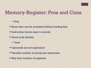
Downloaded 186 times

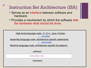
![+ Classifying ISAs
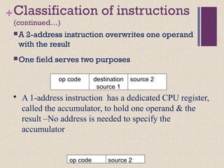
Accumulator (before 1960):
1-address add A acc ¬ acc +
mem[A]
Stack (1960s to 1970s):
0-address add tos ¬ tos + next
Memory-Memory (1970s to 1980s):
2-address add A, B mem[A] ¬
mem[A] + mem[B]
3-address add A, B, C mem[A] ¬
mem[B] + mem[C]](https://image.slidesharecdn.com/lecture34-171231172225/85/Instruction-Set-Architecture-ISA-4-320.jpg)
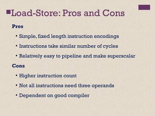
![+
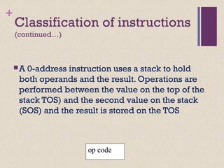
Register-Memory (1970s to present, e.g. 80x86):
2-address add R1, A R1 ¬ R1 + mem[A]
load R1, A R1 ¬ mem[A]
Register-Register (Load/Store) (1960s to present, e.g. MIPS):
3-address add R1, R2, R3 R1 ¬ R2 + R3
load R1, R2 R1 ¬ mem[R2]
store R1, R2 mem[R1] ¬ R2](https://image.slidesharecdn.com/lecture34-171231172225/85/Instruction-Set-Architecture-ISA-5-320.jpg)
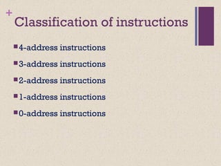
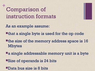
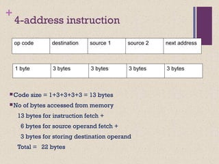
![+ Code Sequence C = A + B
for Four Instruction Sets
Stack Accumulator Register
(register-memory)
Register
(load-store)
Push A
Push B
Add
Pop C
Load A
Add B
Store C
Load R1, A
Add R1, B
Store C, R1
Load R1,A
Load R2, B
Add R3, R1, R2
Store C, R3
memory memory
acc = acc + mem[C] R1 = R1 + mem[C] R3 = R1 + R2](https://image.slidesharecdn.com/lecture34-171231172225/85/Instruction-Set-Architecture-ISA-7-320.jpg)
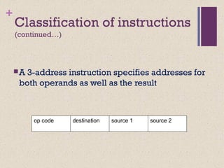
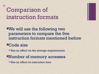
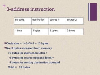
![Accumulator Architectures
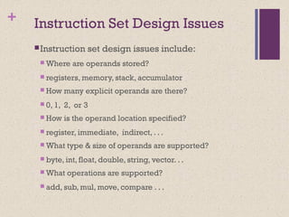
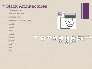
Instruction set:
add A, sub A, mult A, div A, . . .
load A, store A
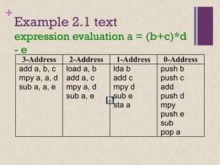
Example: A*B - (A+C*B)
load B
mul C
add A
store D
load A
mul B
sub D
B B*C A+B*C AA+B*C A*B result
acc = acc +,-,*,/ mem[A]](https://image.slidesharecdn.com/lecture34-171231172225/85/Instruction-Set-Architecture-ISA-11-320.jpg)
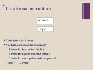
![Register-Memory Architectures
• Instruction set:
add R1, A sub R1, A mul R1, B
load R1, A store R1, A
• Example: A*B - (A+C*B)
load R1, A
mul R1, B /* A*B */
store R1, D
load R2, C
mul R2, B /* C*B */
add R2, A /* A + CB */
sub R2, D /* AB - (A + C*B) */
R1 = R1 +,-,*,/ mem[B]](https://image.slidesharecdn.com/lecture34-171231172225/85/Instruction-Set-Architecture-ISA-15-320.jpg)


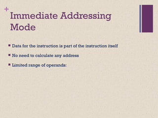
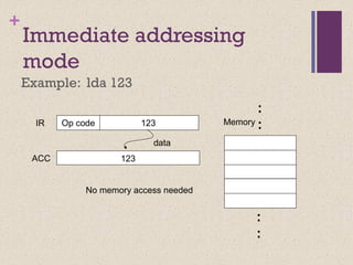
![+
Direct Addressing mode
Example: lda [123] ***
123
Opcode 123
456
456
Memory
.
.
.
data
address
IR
ACC](https://image.slidesharecdn.com/lecture34-171231172225/85/Instruction-Set-Architecture-ISA-35-320.jpg)
![+
Indirect addressing mode
Example: lda [[123]]
456
:
789
Memory
Opcode 123
789
Address of pointer
Address of data
data
123
456
IR
ACC](https://image.slidesharecdn.com/lecture34-171231172225/85/Instruction-Set-Architecture-ISA-36-320.jpg)
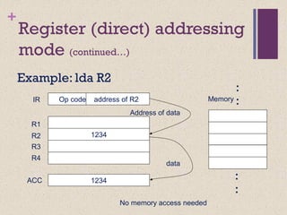
![+Register Indirect Addressing
Example: lda [R1]
456
Op code Address of R1
456
Memory
IR
R1
R2
R3
R4
123
register
contains
memory
address
CPU Registers
data
e instruction points to a CPU register
123
ACC](https://image.slidesharecdn.com/lecture34-171231172225/85/Instruction-Set-Architecture-ISA-38-320.jpg)
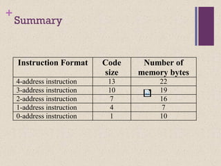
![MemoryExample: lda [ R1 + 8 ]
8IR Op code Address of R1
Register address
R 1
R 2
120
+
Memory
address
Index 456 128
CPU registers
ACC 456
data
Displacement Addressing
constant](https://image.slidesharecdn.com/lecture34-171231172225/85/Instruction-Set-Architecture-ISA-39-320.jpg)


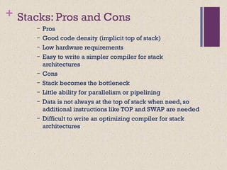
This document discusses instruction set architectures (ISAs). It covers four main types of ISAs: accumulator, stack, memory-memory, and register-based. It also discusses different addressing modes like immediate, direct, indirect, register-indirect, and relative addressing. The key details provided are: 1) Accumulator ISAs use a dedicated register (accumulator) to hold operands and results, while stack ISAs use an implicit last-in, first-out stack. Memory-memory ISAs can have 2-3 operands specified directly in memory. 2) Register-based ISAs can be either register-memory (like 80x86) or load-store (like MIPS), which fully separate