Download to read offline

![Remotely Secured Device Automation using Infrared
(IJSRD/Vol. 1/Issue 3/2013/0045)
All rights reserved by www.ijsrd.com
578
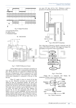
At the end of the receiver circuit, after the
microcontroller unit, a relay circuit is needed to supply
voltage to the appliances. The relay will be triggered on by a
transistor which acts as a switch to increase its stability
figure shows a general circuit of the relay unit.
The transistor is acting as a switch to turn on the
relay unit. The input to turn on the transistor is 5V from the
output pin of microcontroller. This means when the
microcontroller receives a command to switch on the
appliance, it will supply 5V to the transistor to turn on the
transistor. As the transistor is on, the relay which built at the
collector of transistor will be triggered on. The relay
contacts will go from NC (Normally closed) to NO
(Normally On). Hence, the 240VAC will be supplied to the
appliance that connected to the NO pin of the relay. A diode
is connected in parallel with the relay in order to protect the
relay circuit.
REFERENCES
[1]. B. Srinivasa Rao, S.D.V. Prasad and R. Madan Mohan”
A Proto-Type for Home Automation” Beijing
Consumer Electronics, IEEE Transactions vol. 54 pp.
567 – 572, 2012.
[2]. Y.Usha Devi “Wireless Home Automation System
Using ZigBee” International Journal of Scientific &
Engineering Research Volume 3, Issue 8, August-2012
[3]. Mike James Microcontroller Cookbook PIC & 8051,
Butterworth-Heinemann, 2nd
Edition Oxford 2007](https://image.slidesharecdn.com/ijsrdv1i3045-140801070833-phpapp01/85/Remotely-Secured-Device-Automation-using-Infrared-3-320.jpg)

This document describes a remote control system that uses infrared signals to automate and control electrical devices remotely up to 10 meters away. The system uses an HT12E encoder and HT12D decoder, along with a TSOP1738 IR sensor. The encoder generates encoded codes that are modulated with a 38kHz carrier signal from a 555 timer circuit and transmitted via an IR LED. The receiver uses the TSOP1738 sensor to detect the 38kHz IR signals and provides the output to the HT12D decoder. The decoder interprets the address and data signals to control 4 devices by toggling the output pins of a microcontroller. A relay circuit then uses the microcontroller outputs to supply power to the devices being automated.