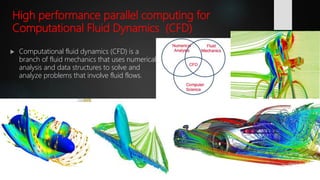
This document discusses the use of high performance computing (HPC) for design, modeling, and simulation software. It provides an overview of HPC and its applications in various engineering fields like construction, automotive, chemical production, and health. Computer aided design software and finite element analysis are important for simulation. HPC can speed up simulations using tools like ANSYS through parallel processing on multiple cores and machines. The document compares performance of HPC on computational fluid dynamics simulations between BAKOO and KHPC parallel computers.


![High‐Performance Computing for
Engineers
When it comes to engineering uses for HPC, the most obvious answer is, of course,
simulation.
Computer simulation is a numbers game in which digital models are pitted against
simulated physics to determine the model's viability. Of course, many calculations have
to be solved for a simulation to be valid, making simulation a prime candidate for
HPC.
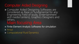
What is Computer Aided Engineering (CAE)?
CAE is the broad usage of computer software to aid in engineering analysis tasks. It includes
finite element analysis (FEA), computational fluid dynamics (CFD), multibody dynamics (MBD),
and optimization. [Wikipedia]
Computer aided Engineering is a very big concept.
Any Engineering Field of Study needs support from computers in order to study, Analyze,
optimize, Design, calculate, visualize, interpret, simulate and other many tasks.
Due to this there are Softwares used to implement or operate the above tasks. This softwares
used to operate this tasks, known as Computer Aided Designing Softwares.](https://image.slidesharecdn.com/finalpresentationppt-180112141128/85/HPC-and-Simulation-5-320.jpg)


![Basic Simulation software
Ansys was founded in 1970 by John Swanson. [Wikipedia]
Ansys software is used to design products and
semiconductors, as well as to create simulations that test a
product's durability, temperature distribution, fluid
movements, and electromagnetic properties.
Ansys can work together with other modelling softwares like
AutoCAD, SolidWorks, Catia, ArchiCAD, Rviet, Autodesk
Inventor, DYNA-3D, CAD-CAM and other softwares.](https://image.slidesharecdn.com/finalpresentationppt-180112141128/85/HPC-and-Simulation-14-320.jpg)


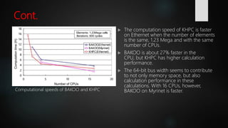
![Conclusion of the study
A self-made parallel computer assembled by using components for
general-purpose personal computers reduces computation time.
A high-speed communication device to replace Ethernet is mandatory
and is an important key technology for parallel computation.
Myrinet was promoted as having lower protocol overhead than
standards such as Ethernet, and therefore better throughput, less
interference, and lower latency while using the host CPU.
Ethernet is a family of computer networking technologies commonly
used in local area networks (LAN), metropolitan area networks
(MAN) and wide area networks (WAN). [Wikipedia].
A system with a good cost vs. performance ratio need to be used for
suiting application of advanced work.](https://image.slidesharecdn.com/finalpresentationppt-180112141128/85/HPC-and-Simulation-27-320.jpg)