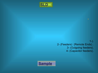
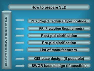
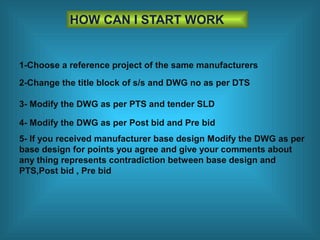
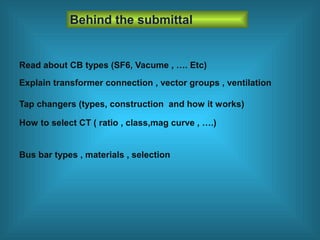
How to prepare SLD
By : Ahmed Metwally
What is SLD
•
SLD
1-).
2- (Feeders) (Remote Ends) .
3- (Outgoing feeders).
4- (Capacitor feeders).
Sample
How to prepare SLD
PTS (Project Technical Specifications)
PR (Protection Requirements)
Post-pid clarification
DocumentsnecessarytopreparetheSLD
GIS base design (if possible)
Pre-pid clarification
SWGR base design (if possible)
List of manufacturers
•
• SLD
PTS
1-).
2- (Feeders) (Remote Ends) .
3- (Outgoing feeders).
4- (Capacitor feeders).
5- (CB) (Earth switch) Bay.
6- Tender SLD SLD
SLD PTS .
Sample
Note
Bay: group of C.B’s, CT’s, VT’s, E.S’s & D.S’s which is
responsible for a certain task.
.
Transformer bay:
CB (D.S’s) (E.S’s) (CT’s) (VT’s)
Bay .
Protection & Metering SLD SLD .
PR (Protection Requirements)
Sample
• .
• :-
Pre-Pid Clarrifications:
Q: All D.S’s will be 3 positions?.
.
SLD 3 position SLD SLD.
Ans: Confirmation.
.
Post-pid Pre-pid :-
Post -pid Clarrifications:
15 VA 25 VA PR PTS.
rating VT calculations Pre-pid 15 VA 25 VA.
Q: VT rating will be 15 VA instead of 25 VA.
Ans: It must satisfy VT requirements.
GIS GAS INSULATED SWITCHGEAR
SWGR
Manufacturer GIS
GIS base design
CB
Sample
Manufacturer SWGR
SWGR base design
CB
BUS SECTION
BUS DUCT
Sample
Note
GIS , SWGR BASE DESIGN MANUFACTURER List of
manufacturers
Sample
HOW CAN I START WORK
1-Choose a reference project of the same manufacturers
2-Change the title block of s/s and DWG no as per DTS
3- Modify the DWG as per PTS and tender SLD
4- Modify the DWG as per Post bid and Pre bid
5- If you received manufacturer base design Modify the DWG as per
base design for points you agree and give your comments about
any thing represents contradiction between base design and
PTS,Post bid , Pre bid
Behind the submittal
Read about CB types (SF6, Vacume , …. Etc)
Explain transformer connection , vector groups , ventilation
Tap changers (types, construction and how it works)
How to select CT ( ratio , class,mag curve , ….)
Bus bar types , materials , selection
QUESTIONS??
THANKS

how to prepare SLD

  • 1.
    How to prepareSLD By : Ahmed Metwally
  • 2.
  • 3.
    • SLD 1-). 2- (Feeders) (RemoteEnds) . 3- (Outgoing feeders). 4- (Capacitor feeders). Sample
  • 4.
    How to prepareSLD PTS (Project Technical Specifications) PR (Protection Requirements) Post-pid clarification DocumentsnecessarytopreparetheSLD GIS base design (if possible) Pre-pid clarification SWGR base design (if possible) List of manufacturers
  • 5.
    • • SLD PTS 1-). 2- (Feeders)(Remote Ends) . 3- (Outgoing feeders). 4- (Capacitor feeders). 5- (CB) (Earth switch) Bay. 6- Tender SLD SLD SLD PTS . Sample
  • 6.
    Note Bay: group ofC.B’s, CT’s, VT’s, E.S’s & D.S’s which is responsible for a certain task. . Transformer bay: CB (D.S’s) (E.S’s) (CT’s) (VT’s)
  • 7.
    Bay . Protection &Metering SLD SLD . PR (Protection Requirements) Sample
  • 8.
    • . • :- Pre-PidClarrifications: Q: All D.S’s will be 3 positions?. . SLD 3 position SLD SLD. Ans: Confirmation.
  • 9.
    . Post-pid Pre-pid :- Post-pid Clarrifications: 15 VA 25 VA PR PTS. rating VT calculations Pre-pid 15 VA 25 VA. Q: VT rating will be 15 VA instead of 25 VA. Ans: It must satisfy VT requirements.
  • 10.
    GIS GAS INSULATEDSWITCHGEAR SWGR Manufacturer GIS GIS base design CB Sample
  • 11.
    Manufacturer SWGR SWGR basedesign CB BUS SECTION BUS DUCT Sample
  • 12.
    Note GIS , SWGRBASE DESIGN MANUFACTURER List of manufacturers Sample
  • 13.
    HOW CAN ISTART WORK 1-Choose a reference project of the same manufacturers 2-Change the title block of s/s and DWG no as per DTS 3- Modify the DWG as per PTS and tender SLD 4- Modify the DWG as per Post bid and Pre bid 5- If you received manufacturer base design Modify the DWG as per base design for points you agree and give your comments about any thing represents contradiction between base design and PTS,Post bid , Pre bid
  • 14.
    Behind the submittal Readabout CB types (SF6, Vacume , …. Etc) Explain transformer connection , vector groups , ventilation Tap changers (types, construction and how it works) How to select CT ( ratio , class,mag curve , ….) Bus bar types , materials , selection
  • 15.
  • 16.

Editor's Notes

  • #16 <number> Sistema de protección de comparación de fase: La protección de cada extremo compara la fase relativa de las intensidades entre extremos de línea, detectando falta si existe desfase superior a uno de tolerancia; este desfase, llamado ángulo de bloqueo, y que está directamente relacionado con la sensibilidad de la protección, es el que compensa los desfases no deseados introducidos por el tiempo de transmisión de la señal y por la intensidad capacitiva en la línea.
  • #17 <number> Sistema de protección de comparación de fase: La protección de cada extremo compara la fase relativa de las intensidades entre extremos de línea, detectando falta si existe desfase superior a uno de tolerancia; este desfase, llamado ángulo de bloqueo, y que está directamente relacionado con la sensibilidad de la protección, es el que compensa los desfases no deseados introducidos por el tiempo de transmisión de la señal y por la intensidad capacitiva en la línea.