DESIGN OF HELICAL GEAR
ON PRO ENGINEER
GEAR
A Gear is a rotating machine part having cut teeth which
mesh with another toothed part to transmit torque.
Geared devices can change the speed, torque, and
direction of a power source.
HELICAL GEAR
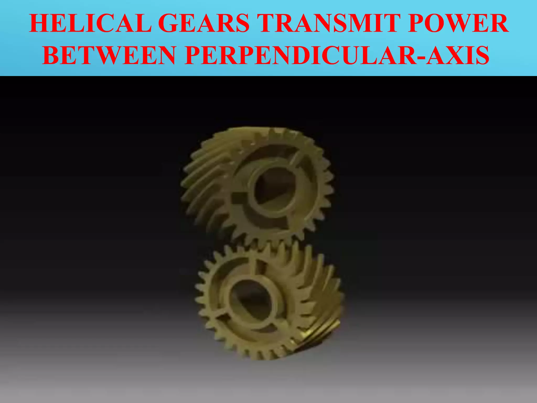
Helical gears are cylindrical gears whose teeth are not
parallel to the axis of rotation. The teeth are angled and
appear as a segment of a helix. Helical gears can
transmit power between parallel or right angle axes.
HELICAL GEARS TRANSMIT POWER
BETWEEN PARALLELAXES
HELICAL GEARS TRANSMIT POWER
BETWEEN PERPENDICULAR-AXIS
TYPES OF HELICAL GEAR
TERMS USED IN HELICAL GEAR
1. Helix angle
It is a constant angle made by the helices with the axis of rotation.
2. Axial pitch
It is the distance, parallel to the axis, between similar faces of adjacent
teeth. It is denoted by pc.
3. Normal pitch
It is the distance between similar faces of adjacent teeth along a helix on
the pitch cylinders normal to the teeth. It is denoted by pN.
Mathematically.
Normal pitch, pN = pc cos B
FACE WIDTH OF HELICAL GEARS
 In case of single Helical Gear
b =1.15 Pc/ tanβ= 1.15*m ×π/tanβ , ( pc = π m)
Where
b = Minimum face width, and
m = Module
 In case of double helical or herringbone gears, the minimum
face width is given by
b =2.3 Pc/tanβ= 2.3*m *π/tanβ
The maximum face width ranges from 20 m to 30 m.
 In single helical gears, the helix angle ranges from 20° to
35°, while for double helical gears, it may be made upto 45°.
STRENGTH OF HELICAL GEAR
 WT =( σo × Cv) b.π m.y‘ where WT = Tangential tooth load
 σo = Allowable static stress
 Cv = Velocity factor
 b = Face width
 m = Module
 y' = Tooth form factor or Lewis factor corresponding to the formative
or virtual or equivalent number of teeth
 The value of velocity factor (Cv) may be taken as follows
Cv = 6 /6 +v for peripheral velocities from 5 m / s to 10 m / s.
=15/15+v for peripheral velocities from 10 m / s to 20 m / s.=
=0.75/0.75+√v for peripheral velocities greater than 20 m / s.
 The dynamic tooth load on the helical gears is given by
WD =
WT +21v ( b cos^2β +WT) cos β/(21v √b.C cos ^2 β+WT)
 The static tooth load or endurance strength of the tooth is
given by
WS = σe.b.π m.y'
NUMERICAL
A pair of helical gears are to transmit 15 kW. The teeth
are 20° stub in diametral. Plane and have a helix angle
of 45°. The pinion runs at 10 000 r.p.m. and has 80 mm
pitch diameter and having shape factor 0.16575 for 20°
stub teeth. If the gears are made of cast steel having
allowable static strength of 100 Mpa
Determine
A Suitable Module
Face width
ADVANTAGES OF HELICAL GEAR
 The angled teeth engage more gradually than do spur gear
teeth causing them to run more smoothly and quietly
 Helical gears are highly durable and are ideal for high load
applications.
 Helical gears can be used on non parallel and even
perpendicular shafts, and can carry higher loads than can
spur gears.
 At any given time their load is distributed over several
teeth, resulting in less wear.
 Can transmit motion and power between either parallel or
right angle shafts.
APPLICATIONS OF HELICAL GEAR
Helical gears are normally preferred to work under heavy
load efficiently.
 Helical gears are used in fertilizer industries, Printing
industries and earth moving industries.
 Helical gears are also used in steel, Rolling mills, section
rolling mills, power and port industries.
 Helical gears are also used in textile industries, plastic
industries, food industries, conveyors, elevators,
blowers, compressors, oil industries & cutters.
THANK YOU

Helical gear

  • 2.
    DESIGN OF HELICALGEAR ON PRO ENGINEER
  • 3.
    GEAR A Gear isa rotating machine part having cut teeth which mesh with another toothed part to transmit torque. Geared devices can change the speed, torque, and direction of a power source.
  • 4.
    HELICAL GEAR Helical gearsare cylindrical gears whose teeth are not parallel to the axis of rotation. The teeth are angled and appear as a segment of a helix. Helical gears can transmit power between parallel or right angle axes.
  • 5.
    HELICAL GEARS TRANSMITPOWER BETWEEN PARALLELAXES
  • 6.
    HELICAL GEARS TRANSMITPOWER BETWEEN PERPENDICULAR-AXIS
  • 7.
  • 8.
    TERMS USED INHELICAL GEAR 1. Helix angle It is a constant angle made by the helices with the axis of rotation. 2. Axial pitch It is the distance, parallel to the axis, between similar faces of adjacent teeth. It is denoted by pc. 3. Normal pitch It is the distance between similar faces of adjacent teeth along a helix on the pitch cylinders normal to the teeth. It is denoted by pN. Mathematically. Normal pitch, pN = pc cos B
  • 9.
    FACE WIDTH OFHELICAL GEARS  In case of single Helical Gear b =1.15 Pc/ tanβ= 1.15*m ×π/tanβ , ( pc = π m) Where b = Minimum face width, and m = Module  In case of double helical or herringbone gears, the minimum face width is given by b =2.3 Pc/tanβ= 2.3*m *π/tanβ The maximum face width ranges from 20 m to 30 m.  In single helical gears, the helix angle ranges from 20° to 35°, while for double helical gears, it may be made upto 45°.
  • 10.
    STRENGTH OF HELICALGEAR  WT =( σo × Cv) b.π m.y‘ where WT = Tangential tooth load  σo = Allowable static stress  Cv = Velocity factor  b = Face width  m = Module  y' = Tooth form factor or Lewis factor corresponding to the formative or virtual or equivalent number of teeth  The value of velocity factor (Cv) may be taken as follows Cv = 6 /6 +v for peripheral velocities from 5 m / s to 10 m / s. =15/15+v for peripheral velocities from 10 m / s to 20 m / s.= =0.75/0.75+√v for peripheral velocities greater than 20 m / s.
  • 11.
     The dynamictooth load on the helical gears is given by WD = WT +21v ( b cos^2β +WT) cos β/(21v √b.C cos ^2 β+WT)  The static tooth load or endurance strength of the tooth is given by WS = σe.b.π m.y'
  • 12.
    NUMERICAL A pair ofhelical gears are to transmit 15 kW. The teeth are 20° stub in diametral. Plane and have a helix angle of 45°. The pinion runs at 10 000 r.p.m. and has 80 mm pitch diameter and having shape factor 0.16575 for 20° stub teeth. If the gears are made of cast steel having allowable static strength of 100 Mpa Determine A Suitable Module Face width
  • 13.
    ADVANTAGES OF HELICALGEAR  The angled teeth engage more gradually than do spur gear teeth causing them to run more smoothly and quietly  Helical gears are highly durable and are ideal for high load applications.  Helical gears can be used on non parallel and even perpendicular shafts, and can carry higher loads than can spur gears.  At any given time their load is distributed over several teeth, resulting in less wear.  Can transmit motion and power between either parallel or right angle shafts.
  • 14.
    APPLICATIONS OF HELICALGEAR Helical gears are normally preferred to work under heavy load efficiently.  Helical gears are used in fertilizer industries, Printing industries and earth moving industries.  Helical gears are also used in steel, Rolling mills, section rolling mills, power and port industries.  Helical gears are also used in textile industries, plastic industries, food industries, conveyors, elevators, blowers, compressors, oil industries & cutters.
  • 15.