Content:
 Pavement Component functions
 Types of Pavement
 Factors affecting pavement design
 Basic pavement design of Flexible and Rigid pavement as per
IRC guidelines
 Pavement Maintenance
Highway Pavement:
A highway pavement is a structure consisting of
superimposed layers of processed materials above the
natural soil sub-grade, whose primary function is to
distribute the applied vehicle loads to the sub-grade.
Introduction to Pavement Design
An ideal pavement should meet the following requirements:
Sufficient thickness to distribute the wheel load stresses to a safe value on the sub-
grade soil,
Structurally strong to withstand all types of stresses imposed upon it,
Adequate coefficient of friction to prevent skidding of vehicles,
Smooth surface to provide comfort to road users even at high speed,
Produce least noise from moving vehicles,
Dust proof surface so that traffic safety is not impaired by reducing visibility,
Impervious surface, so that sub-grade soil is well protected, and
Long design life with low maintenance cost.
Requirements of a pavement
TYPES OF PAVEMENTS
TYPES OF PAVEMENTS
Following are the two main types of pavements:
1. Flexible pavement
2. Rigid pavement
Flexible pavements are those pavements that reflect the deformation of sub
grade and the subsequent layers to the surface.
 Flexible, usually asphalt, is laid with no reinforcement or with a
specialized fabric reinforcement that permits limited flow or
repositioning of the roadbed underground changes.
 The design of flexible pavement is based on load distributing
characteristics of the component layers.
 The black top pavement including water & gravel bound macadam fall
in this category.
 Flexible pavement on the whole has low or negligible flexible strength
flexible in their structural action.
FLEXIBLE PAVEMENT
 The flexible pavement layers transmit the vertical or compressive
stresses to the lower layers by grain transfer through contact points of
granular structure.
 The vertical compressive stress is maximum on the pavement surface
directly under the wheel load and is equal to contact pressure under the
wheels.
 Due to the ability to distribute the stress to large area in the shape of
truncated cone the stresses get decreased in the lower layer.
 As such the flexible pavement may be constructed in a number of layers
and the top layer has to be strongest as the highest compressive stresses.
 To be sustained by this layer, in addition to wear and tear, the lower layer
have to take up only lesser magnitude of stress as there is no direct
wearing action due to traffic loads.
 Therefore, inferior material with lower cost can be used in the lower
layers
The wheel load acting on the pavement will
be distributed to a wider area, and the
stress decreases with the depth. Taking
advantage of this stress distribution
characteristic, flexible pavements normally
have many layers.
Seal Coat: Seal coat is a thin surface treatment
used to water-proof the surface and to provide
skid resistance.
Tack Coat: Tack coat is a very light application
of asphalt, usually asphalt emulsion diluted
with water. It provides proper bonding
between two layer of binder course and must
be thin, uniformly cover the entire surface, and
set very fast.
Prime Coat: Prime coat is an application of
low viscous cutback bitumen to an absorbent
surface like granular bases on which binder
layer is placed. It provides bonding between
two layers. Unlike tack coat, prime coat
penetrates into the layer below, plugs the voids,
and forms a water tight surface.
Typical Cross section of Flexible Pavement
Surface course: Surface course is the
layer directly in contact with trac loads and
generally contains superior quality
materials. They are usually constructed
with dense graded asphalt concrete(AC).
Binder course: This layer provides the bulk
of the asphalt concrete structure. It's chief
purpose is to distribute load to the base
course. The binder course generally consists
of aggregates having less asphalt and doesn't
require quality as high as the surface course,
so replacing a part of the surface course by
the binder course results in more economical
design.
Base course: The base course is the layer of
material immediately beneath the surface of
binder course and it provides additional load
distribution and contributes to the sub-
surface drainage. It may be composed of
crushed stone, crushed slag, and other
untreated or stabilized materials.
For example: A pavement constructed over a high quality, sub-grade may not need the additional
features offered by a sub-base course. In such situations, sub-base course may not be provided.
Sub-Base course: The sub-base
course is the layer of material
beneath the base course and the
primary functions are to provide
structural support, improve drainage,
and reduce the intrusion of fines from
the sub-grade in the pavement
structure. If the base course is open
graded, then the sub-base course
with more fines can serve as a filler
between sub-grade and the base
course. A sub-base course is not
always needed or used.
Sub-grade: The top soil or sub-grade is a layer of natural soil prepared to receive
the stresses from the layers above. It is essential that at no time soil sub-grade is
overstressed. It should be compacted to the desirable density, near the optimum
moisture content.
Construction……
Conventional flexible pavements are layered systems with high quality expensive
materials are placed in the top where stresses are high, and low quality cheap materials
are placed in lower layers.
Full - depth asphalt pavements are constructed by placing bituminous layers directly
on the soil sub-grade. This is more suitable when there is high traffic and local
materials are not available. Contained rock asphalt mats are constructed by placing
dense/open graded aggregate layers in between two asphalt layers.
Modified dense graded asphalt concrete is placed above the sub-grade will
significantly reduce the vertical compressive strain on soil sub-grade and protect from
surface water.
Types of Flexible Pavements
The major flexible pavements are:
 Fatigue Cracking
 Rutting
 Thermal Cracking
Failure of flexible pavements:
Fatigue cracking is caused by tensile strain at the bottom of the asphalt
layer. Rutting is caused by accumulated permanent deformations on
the road surface.
 The rigid characteristics of the pavement are associated with rigidity or
flexural strength or slab action so the load is distributed over a wide area of
subgrade soil.
 Rigid pavement is laid in slabs with steel reinforcement.
 The rigid pavements are made of cement concrete either plain, reinforced
or pre-stressed concrete.
 Critical condition of stress in the rigid pavement is the maximum flexural
stress occurring in the slab due to wheel load and temperature changes.
 Rigid pavement is designed and analyzed by using the elastic theory.
RIGID PAVEMENT
Rigid pavements have sufficient flexural strength to transmit the wheel load
stresses to a wider area below. In rigid pavement, load is distributed by the slab
action, and the pavement behaves like an elastic plate resting on a viscous
medium.
TYPICAL C/S OF RIGID PAVEMENT
 Rigid lasts much, much longer i.e 30+ years compared to 5-10 years of
flexible pavements.
 In the long run it is about half the cost to install and maintain. But the
initial costs are somewhat high.
 Rigid pavement has the ability to bridge small imperfections in the
sub grade.
 Less Maintenance cost and Continuous Traffic and Flow.
 High efficiency in terms of functionality.
ADVANTAGES OF RIGID PAVEMENT
Jointed Plain Concrete Pavements: These are plain cement concrete pavements
constructed with closely spaced contraction joints. Dowel bars or aggregate interlocks
are normally used for load transfer across joints. They normally have a joint spacing of
5 to 10m.
Jointed Reinforced Concrete Pavement: Although reinforcements do not improve
the structural capacity significantly, they can drastically increase the joint spacing to
10 to 30m. Dowel bars are required for load transfer. Reinforcement helps to keep the
slab together even after cracks.
Continuous Reinforced Concrete Pavement: Complete elimination of joints are
achieved by reinforcement.
Pre-stressed Concrete Pavements:
Types of Rigid Pavements:
 Traditionally fatigue cracking has been considered as the major, or only
criterion for rigid pavement design.
 Of late, pumping is identified as an important failure criterion.
Failure criteria of rigid pavements
The expulsion of water from the under a layer of the
pavement is called as pumping. This distress is caused due to
the active vehicle loads coming over the pavement in a
repetitive manner. This will result in the fine materials
present in the sub base to move along with water and get
expelled out with the water.
FLEXIBLE PAVEMENTS RIGID PAVEMENTS
• Deformation in the sub grade is transferred to
the upper layers
• Design is based on load distributing
characteristics of the component layers
• low flexural strength , completion cost and life
span
• Load is transferred by grain to grain contact
• repairing cost is high
• Surfacing cannot be laid directly on the sub
grade but a sub base is needed
• No thermal stresses are induced in the
pavement.
• That's why expansion joints are not needed
• Strength dependent on the strength of the sub
grade
• Rolling of the surfacing is needed
• Road can be used for traffic within 24 hours
• Force of friction is less.
• Deformation in the sub grade is not transferred to
subsequent layers
• Design is based on flexural strength or slab action
• Have high flexural strength and Life span
• No such phenomenon of grain to grain load
transfer exists
• Have low repairing cost but completion cost is high
• Surfacing can be directly laid on the sub grade
• Thermal stresses are more vulnerable to be
induced as the ability to contract and expand is
very less in concrete
• That's why expansion joints are needed
• Strength of the road is less dependent on the
strength of the sub grade
• Rolling of the surfacing in not needed
• Road cannot be used until 14 days of curing
• Force of friction is high.
2. Dense Bituminous Macadam (DBM)
Composition: A mixture of aggregates, bitumen, and filler, designed to provide a dense, strong
layer.
Purpose: Acts as a base or binder course in asphalt pavements, providing strength and durability.
Thickness: Generally ranges from 50 mm to 100 mm.
Benefits: Offers high resistance to deformation, good waterproofing, and is effective in providing a
smooth surface.
In road construction, GSB (Granular Sub Base), DBM (Dense Bituminous Macadam), and
WBM (Water Bound Macadam) are different types of layers used for pavement structure.
Here’s a breakdown of each:
1. Granular Sub Base (GSB)
Composition: Made from granular materials like crushed stone, gravel, or sand.
Purpose: Acts as a load-bearing layer that provides structural support to the road. It also helps
with drainage.
Thickness: Typically ranges from 100 mm to 300 mm, depending on design requirements.
Benefits: Improves load distribution, enhances drainage, and prevents the contamination of the
subgrade.
Summary….
GSB is used mainly for subgrade support and drainage.
DBM provides a strong, durable surface layer in asphalt pavements.
WBM is a more economical option for lower-traffic roads, relying on water for binding.
Each of these materials plays a crucial role in the structural integrity and longevity of
roadways, and the choice among them depends on traffic loads, environmental
conditions, and budgetary constraints.
3. Water Bound Macadam (WBM)
Composition: Consists of stone aggregates bound together with water and a small amount of
binding material (like stone dust).
Purpose: Used as a base course in unpaved or low-traffic roads.
Thickness: Usually between 150 mm to 300 mm.
Benefits: Easy to construct, provides good drainage, and is cost-effective for low-traffic areas.
However, it has lower strength compared to DBM.
Factors affecting
Pavement Design
There are so many factors which influencing the pavement design. The factors may be
of loading, environment, materials used etc. Which are as follows.
Wheel load
Axle configuration
Contact pressure
Vehicle speed
Repetition of loads
Subgrade type
Temperature
Precipitation
Factors Affecting Pavement Design
Wheel load on pavement is an
important factor to determine
the pavement thickness to be
adopted.
By providing adequate thickness,
the load coming from wheels
doesn’t affect the subgrade soil.
The wheel load is acts at
particular point on pavement
and cause deformations. Wheel Load Influence on Pavement Design
1. Wheel Load Influence on Pavements
If the vehicle contains dual wheels on one side of axle, then convert it into equivalent
single wheel load. Dual wheeled axle vehicles control the contact pressure within the
limits.
Axles are the important part of the vehicles
which enables the wheels to rotate while
moving. By providing multiple axles, vehicles
can carry more load. So, the axle load also
influences the design of pavement. In the
layer theory of flexible pavement design
wheels on one side of axles are considered to
design the pavement. Similarly in the plate
theory of rigid pavement design wheels on
both sides are considered.
Effect of Axle Configuration on Pavement Design
2. Axle Configuration
When the vehicle is moving on
pavement, the pressure developed
between the tire and pavement. If the
tire is low-pressure tire, then contact
pressure will be greater than tire
pressure. If it is a high-pressure tire,
then contact pressure will be less than
tire pressure. The original Shape of the
contact area is generally elliptical. But
to ease the calculations circular shape
is considered
Tire Contact Pressure on Pavement
3. Tire Contact Pressure on Pavement
If the vehicle is moving at creep speed then also damage occurs to
the pavement. If the vehicle speed is gradually increased then it will
cause smaller strains in the pavement.
4. Vehicle Speed
Constructed pavement is used by several
vehicles in its design life. The wheel loads are
repeated all the time due to this some
deformation occurs on the pavement. Total
deformation is the sum of all-wheel loads
acting on it. So, in the design of pavement
frequency of load is also considered. For the
design of pavement, a single axle with dual
wheels carrying 80 kN load is considered a
standard axle.
Axle Load on Pavement
5. Repetition of Loads
To construct pavement subgrade soil
need to be tested. Various test like CBR,
Triaxial, etc. will help to determine the
quality of subgrade. From this, we can
adapt the required thickness to the
pavement. If subgrade soil is poor then
the pavement should damage easily.
Effect of Subgrade Type on Pavement Design
6. Subgrade Type
Temperature is the important environmental
factor to be considered in the design of
pavement. In the case of asphalt roads,
temperature affects the resilient modulus of
the surface course. In very hot conditions
asphalt layers lose their stiffness. At low
temperatures, asphalt layers become brittle
and cracks are formed.
Temperature Effects on Pavements Design
In case of rigid pavement, temperature stresses are developed. Curling of concrete is
also possible due to variation of temperature in the top and bottom layers of
pavement.
7. Temperature Effects on Pavements Design
8. Precipitation
Effect of Rain on Pavement Design
Moisture variations or precipitation from rain
affects the depth of the groundwater table. Good
drainage facilities should be provided for good
strength and support.
The groundwater table should be at least below
1m from the pavement surface.
Basic pavement design of
Flexible and Rigid pavement as
per IRC guidelines
Group Index
Group Index is an arbitrary index assigned to the soil types based on percentage fines,
liquid limit and plasticity index. It helps in grading of the soils. Its value ranges from 0 to
20. The higher GI value, Poorer the sub grade soil, more the thickness of pavement.
Lesser its value, Higher the grade of soil.
Group Index, GI=0.2a+0.005ac+0.01bd
a= value of that portion of the material passing through 0.075mm sieve in the excess of
35% but not exceed 75% ( its value should be whole number and number from 0 to 40).
b= value of that portion of the material passing through 0.075mm sieve in excess of
15% but not exceed 55% ( its value should be whole number and ranges from 0 to 40).
c= liquid limit in excess of 40% and not more than 60%. Its value should be whole
numbers and ranges from 0 to 20.
d= plasticity index exceeding 10% and not more than 30% . It ranges from 0 to 20.
Traffic Type
Traffic Volume is divided into 3 groups based on the CVPD (Commercial vehicle per
day)
Traffic Type CVPD
Light <50
Medium 50-300
Heavy >300
From the graph, we can easily calculate the value of thickness of pavement
corresponding the value of Group Index and Traffic Type.
In the graph, the darked line represent combined thickness of surface, base, sub base
course and dotted line represent the thickness of surface and base.
IRC method of design of flexible pavements
Overview
Indian roads congress has specified the design procedures for flexible pavements
based on CBR values. The Pavement designs given in the previous edition IRC:37-1984
were applicable to design traffic upto only 30 million standard axles (msa). The earlier
code is empirical in nature which has limitations regarding applicability and
extrapolation. This guidelines follows analytical designs and developed new set of
designs up to 150 msa in IRC:37-2001.
Scope
These guidelines will apply to design of flexible pavements for Expressway, National
Highways, State Highways, Major District Roads, and other categories of roads. Flexible
pavements are considered to include the pavements which have bituminous surfacing
and granular base and sub-base courses conforming to IRC/ MOST standards. These
guidelines apply to new pavements.
Design criteria
The flexible pavements has been modeled as a three layer structure and stresses and
strains at critical locations have been computed using the linear elastic model. To give
proper consideration to the aspects of performance, the following three types of
pavement distress resulting from repeated (cyclic) application of traffic loads are
considered:
 vertical compressive strain at the top of the sub-grade which can cause sub-grade
deformation resulting in permanent deformation at the pavement surface.
 horizontal tensile strain or stress at the bottom of the bituminous layer which can
cause fracture of the bituminous layer.
 pavement deformation within the bituminous layer.
While the permanent deformation within the bituminous layer can be controlled by
meeting the mix design requirements, thickness of granular and bituminous layers are
selected using the analytical design approach so that strains at the critical points are
within the allowable limits. For calculating tensile strains at the bottom of the
bituminous layer, the stiffness of dense bituminous macadam (DBM) layer with 60/70
bitumen has been used in the analysis.
Failure Criteria
Critical locations in pavement
A and B are the critical locations for tensile
strains. Maximum value of the strain is
adopted for design. C is the critical location for
the vertical subgrade strain since the
maximum value of the occurs mostly at C.
Fatigue Criteria: Bituminous surfacing of
pavements display flexural fatigue cracking if
the tensile strain at the bottom of the
bituminous layer is beyond certain limit. The
relation between the fatigue life of the
pavement and the tensile strain in the bottom
of the bituminous layer was obtained as
in which, Nf is the allowable number of load repetitions to control fatigue
cracking and is the Elastic modulus of bituminous layer. The use of
equation would result in fatigue cracking of 20% of the total area.
Rutting Criteria The allowable number of load repetitions to control permanent
deformation can be expressed as
is the number of cumulative standard axles to produce rutting of 20 mm.
Based on the performance of existing designs and using analytical approach,
simple design charts and a catalogue of pavement designs are added in the code.
The pavement designs are given for subgrade CBR values ranging from 2% to 10%
and design traffic ranging from 1 msa to 150 msa for an average annual pavement
temperature of 35 C. The later thicknesses obtained from the analysis have been
slightly modified to adapt the designs to stage construction. Using the following
simple input parameters, appropriate designs could be chosen for the given traffic
and soil strength:
 Design traffic in terms of cumulative number of standard axles; and
 CBR value of subgrade.
Design procedure
The method considers traffic in terms of the cumulative number of standard axles
(8160 kg) to be carried by the pavement during the design life.
This requires the following information:
 Initial traffic in terms of CVPD (Commercial Vehicles Per Day)
 Traffic growth rate during the design life
 Design life in number of years
 Vehicle damage factor (VDF)
 Distribution of commercial traffic over the carriage way.
Design traffic
Initial traffic
Initial traffic is determined in terms of commercial vehicles per day (CVPD). For the
structural design of the pavement only commercial vehicles are considered assuming
laden weight of three tonnes or more and their axle loading will be considered.
Estimate of the initial daily average traffic flow for any road should normally be based
on 7-day 24-hour classified traffic counts (ADT). In case of new roads, traffic estimates
can be made on the basis of potential land use and traffic on existing routes in the
area.
Traffic growth rate
Traffic growth rates can be estimated
(i) by studying the past trends of traffic growth, and
(ii) by establishing econometric models. If adequate data is not available, it is
recommended that an average annual growth rate of 7.5 percent may be adopted.
Design life
For the purpose of the pavement design, the design life is defined in terms of the
cumulative number of standard axles that can be carried before strengthening of the
pavement is necessary. It is recommended that pavements for arterial roads like NH,
SH should be designed for a life of 15 years, EH and urban roads for 20 years and
other categories of roads for 10 to 15 years.
Vehicle Damage Factor
The vehicle damage factor (VDF) is a multiplier for converting the number of
commercial vehicles of different axle loads and axle configurations to the number of
standard axle-load repetitions. It is defined as equivalent number of standard axles
per commercial vehicle. The VDF varies with the axle configuration, axle loading,
terrain, type of road, and from region to region. The axle load equivalency factors are
used to convert different axle load repetitions into equivalent standard axle load
repetitions. For these equivalency factors refer IRC:37 2001. The exact VDF values are
arrived after extensive field surveys.
Vehicle distribution
A realistic assessment of distribution of commercial traffic by direction
and by lane is necessary as it directly affects the total equivalent standard
axle load application used in the design. Until reliable data is available, the
following distribution may be assumed.
 Single lane roads: Traffic tends to be more channelized on
single roads than two lane roads and to allow for this
concentration of wheel load repetitions, the design should be
based on total number of commercial vehicles in both directions.
 Two-lane single carriageway roads: The design should be
based on 75 % of the commercial vehicles in both directions.
 Four-lane single carriageway roads: The design should be
based on 40 % of the total number of commercial vehicles in
both directions.
 Dual carriageway roads: For the design of dual two-lane
carriageway roads should be based on 75 % of the number of
commercial vehicles in each direction. For dual three-lane
carriageway and dual four-lane carriageway the distribution
factor will be 60 % and 45 % respectively.
Design traffic
The design traffic is considered in terms of the cumulative number of standard
axles in the lane carrying maximum traffic during the design life of the road. This
can be computed using the following equation:
where, is the cumulative number of standard axles to be catered for the design in terms of million
standards axle (msa), is the initial traffic in the year of completion of construction in terms of the
number of commercial vehicles per day, is the lane distribution factors, is the vehicle damage
factor, is the design life in years, and is the annual growth rate of commercial vehicles ( =-0.075 if
growth rate is 7.5 percent per annum). The traffic in the year of completion is estimated using the
following formula:
where is the number of commercial vehicles as per last count, and x is the number of years between the last
count and the year of completion between the last count and the year of completion of the project.
Pavement thickness design charts
For the design of pavements to carry traffic in the range of 1 to 10 msa, use chart
1 and for traffic in the range 10 to 150 msa, use chart 2 of IRC:37 2001. The
design curves relate pavement thickness to the cumulative number of standard
axles to be carried over the design life for different sub-grade CBR values ranging
from 2 % to 10 %.
The design charts will give the total thickness of the pavement for the above
inputs. The total thickness consists of granular sub-base, granular base and
bituminous surfacing.
The individual layers are designed based on the the recommendations given
below and the subsequent tables.
Pavement composition
Sub-base: Sub-base materials comprise natural sand, gravel, laterite, brick metal, crushed stone
or combinations thereof meeting the prescribed grading and physical requirements. The sub-base
material should have a minimum CBR of 20 % and 30 % for traffic upto 2 msa and traffic
exceeding 2 msa respectively. Sub-base usually consist of granular or WBM and the thickness
should not be less than 150 mm for design traffic less than 10 msa and 200 mm for design traffic
of 1:0 msa and above.
Base: The recommended designs are for unbounded granular bases which comprise
conventional water bound macadam (WBM) or wet mix macadam (WMM) or equivalent
confirming to MOST specifications. The materials should be of good quality with minimum
thickness of 225 mm for traffic up to 2 msa an 150 mm for traffic exceeding 2 msa.
Bituminous surfacing: The surfacing consists of a wearing course or a binder course plus
wearing course. The most commonly used wearing courses are surface dressing, open graded
premix carpet, mix seal surfacing, semi-dense bituminous concrete and bituminous concrete. For
binder course, MOST specifies, it is desirable to use bituminous macadam (BM) for traffic upto o 5
msa and dense bituminous macadam (DBM) for traffic more than 5 msa.
Numerical example
Design the pavement for construction of a new bypass with the following data:
 Two lane carriage way
 Initial traffic in the year of completion of construction = 400 CVPD (sum of both directions)
 Traffic growth rate = 7.5 %
 Design life = 15 years
 Vehicle damage factor based on axle load survey = 2.5 standard axle per commercial vehicle
 Design CBR of subgrade soil = 4%.
HE material_highway designྀིྀིྀིྀིྀིྀིྀིྀི

HE material_highway designྀིྀིྀིྀིྀིྀིྀིྀི

  • 1.
    Content:  Pavement Componentfunctions  Types of Pavement  Factors affecting pavement design  Basic pavement design of Flexible and Rigid pavement as per IRC guidelines  Pavement Maintenance Highway Pavement:
  • 2.
    A highway pavementis a structure consisting of superimposed layers of processed materials above the natural soil sub-grade, whose primary function is to distribute the applied vehicle loads to the sub-grade. Introduction to Pavement Design
  • 3.
    An ideal pavementshould meet the following requirements: Sufficient thickness to distribute the wheel load stresses to a safe value on the sub- grade soil, Structurally strong to withstand all types of stresses imposed upon it, Adequate coefficient of friction to prevent skidding of vehicles, Smooth surface to provide comfort to road users even at high speed, Produce least noise from moving vehicles, Dust proof surface so that traffic safety is not impaired by reducing visibility, Impervious surface, so that sub-grade soil is well protected, and Long design life with low maintenance cost. Requirements of a pavement
  • 4.
  • 5.
    TYPES OF PAVEMENTS Followingare the two main types of pavements: 1. Flexible pavement 2. Rigid pavement
  • 8.
    Flexible pavements arethose pavements that reflect the deformation of sub grade and the subsequent layers to the surface.  Flexible, usually asphalt, is laid with no reinforcement or with a specialized fabric reinforcement that permits limited flow or repositioning of the roadbed underground changes.  The design of flexible pavement is based on load distributing characteristics of the component layers.  The black top pavement including water & gravel bound macadam fall in this category.  Flexible pavement on the whole has low or negligible flexible strength flexible in their structural action. FLEXIBLE PAVEMENT
  • 9.
     The flexiblepavement layers transmit the vertical or compressive stresses to the lower layers by grain transfer through contact points of granular structure.  The vertical compressive stress is maximum on the pavement surface directly under the wheel load and is equal to contact pressure under the wheels.  Due to the ability to distribute the stress to large area in the shape of truncated cone the stresses get decreased in the lower layer.  As such the flexible pavement may be constructed in a number of layers and the top layer has to be strongest as the highest compressive stresses.  To be sustained by this layer, in addition to wear and tear, the lower layer have to take up only lesser magnitude of stress as there is no direct wearing action due to traffic loads.  Therefore, inferior material with lower cost can be used in the lower layers
  • 12.
    The wheel loadacting on the pavement will be distributed to a wider area, and the stress decreases with the depth. Taking advantage of this stress distribution characteristic, flexible pavements normally have many layers.
  • 14.
    Seal Coat: Sealcoat is a thin surface treatment used to water-proof the surface and to provide skid resistance. Tack Coat: Tack coat is a very light application of asphalt, usually asphalt emulsion diluted with water. It provides proper bonding between two layer of binder course and must be thin, uniformly cover the entire surface, and set very fast. Prime Coat: Prime coat is an application of low viscous cutback bitumen to an absorbent surface like granular bases on which binder layer is placed. It provides bonding between two layers. Unlike tack coat, prime coat penetrates into the layer below, plugs the voids, and forms a water tight surface. Typical Cross section of Flexible Pavement Surface course: Surface course is the layer directly in contact with trac loads and generally contains superior quality materials. They are usually constructed with dense graded asphalt concrete(AC).
  • 17.
    Binder course: Thislayer provides the bulk of the asphalt concrete structure. It's chief purpose is to distribute load to the base course. The binder course generally consists of aggregates having less asphalt and doesn't require quality as high as the surface course, so replacing a part of the surface course by the binder course results in more economical design. Base course: The base course is the layer of material immediately beneath the surface of binder course and it provides additional load distribution and contributes to the sub- surface drainage. It may be composed of crushed stone, crushed slag, and other untreated or stabilized materials.
  • 18.
    For example: Apavement constructed over a high quality, sub-grade may not need the additional features offered by a sub-base course. In such situations, sub-base course may not be provided. Sub-Base course: The sub-base course is the layer of material beneath the base course and the primary functions are to provide structural support, improve drainage, and reduce the intrusion of fines from the sub-grade in the pavement structure. If the base course is open graded, then the sub-base course with more fines can serve as a filler between sub-grade and the base course. A sub-base course is not always needed or used.
  • 20.
    Sub-grade: The topsoil or sub-grade is a layer of natural soil prepared to receive the stresses from the layers above. It is essential that at no time soil sub-grade is overstressed. It should be compacted to the desirable density, near the optimum moisture content.
  • 21.
  • 22.
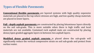
    Conventional flexible pavementsare layered systems with high quality expensive materials are placed in the top where stresses are high, and low quality cheap materials are placed in lower layers. Full - depth asphalt pavements are constructed by placing bituminous layers directly on the soil sub-grade. This is more suitable when there is high traffic and local materials are not available. Contained rock asphalt mats are constructed by placing dense/open graded aggregate layers in between two asphalt layers. Modified dense graded asphalt concrete is placed above the sub-grade will significantly reduce the vertical compressive strain on soil sub-grade and protect from surface water. Types of Flexible Pavements
  • 23.
    The major flexiblepavements are:  Fatigue Cracking  Rutting  Thermal Cracking Failure of flexible pavements: Fatigue cracking is caused by tensile strain at the bottom of the asphalt layer. Rutting is caused by accumulated permanent deformations on the road surface.
  • 25.
     The rigidcharacteristics of the pavement are associated with rigidity or flexural strength or slab action so the load is distributed over a wide area of subgrade soil.  Rigid pavement is laid in slabs with steel reinforcement.  The rigid pavements are made of cement concrete either plain, reinforced or pre-stressed concrete.  Critical condition of stress in the rigid pavement is the maximum flexural stress occurring in the slab due to wheel load and temperature changes.  Rigid pavement is designed and analyzed by using the elastic theory. RIGID PAVEMENT
  • 27.
    Rigid pavements havesufficient flexural strength to transmit the wheel load stresses to a wider area below. In rigid pavement, load is distributed by the slab action, and the pavement behaves like an elastic plate resting on a viscous medium. TYPICAL C/S OF RIGID PAVEMENT
  • 28.
     Rigid lastsmuch, much longer i.e 30+ years compared to 5-10 years of flexible pavements.  In the long run it is about half the cost to install and maintain. But the initial costs are somewhat high.  Rigid pavement has the ability to bridge small imperfections in the sub grade.  Less Maintenance cost and Continuous Traffic and Flow.  High efficiency in terms of functionality. ADVANTAGES OF RIGID PAVEMENT
  • 29.
    Jointed Plain ConcretePavements: These are plain cement concrete pavements constructed with closely spaced contraction joints. Dowel bars or aggregate interlocks are normally used for load transfer across joints. They normally have a joint spacing of 5 to 10m. Jointed Reinforced Concrete Pavement: Although reinforcements do not improve the structural capacity significantly, they can drastically increase the joint spacing to 10 to 30m. Dowel bars are required for load transfer. Reinforcement helps to keep the slab together even after cracks. Continuous Reinforced Concrete Pavement: Complete elimination of joints are achieved by reinforcement. Pre-stressed Concrete Pavements: Types of Rigid Pavements:
  • 30.
     Traditionally fatiguecracking has been considered as the major, or only criterion for rigid pavement design.  Of late, pumping is identified as an important failure criterion. Failure criteria of rigid pavements The expulsion of water from the under a layer of the pavement is called as pumping. This distress is caused due to the active vehicle loads coming over the pavement in a repetitive manner. This will result in the fine materials present in the sub base to move along with water and get expelled out with the water.
  • 31.
    FLEXIBLE PAVEMENTS RIGIDPAVEMENTS • Deformation in the sub grade is transferred to the upper layers • Design is based on load distributing characteristics of the component layers • low flexural strength , completion cost and life span • Load is transferred by grain to grain contact • repairing cost is high • Surfacing cannot be laid directly on the sub grade but a sub base is needed • No thermal stresses are induced in the pavement. • That's why expansion joints are not needed • Strength dependent on the strength of the sub grade • Rolling of the surfacing is needed • Road can be used for traffic within 24 hours • Force of friction is less. • Deformation in the sub grade is not transferred to subsequent layers • Design is based on flexural strength or slab action • Have high flexural strength and Life span • No such phenomenon of grain to grain load transfer exists • Have low repairing cost but completion cost is high • Surfacing can be directly laid on the sub grade • Thermal stresses are more vulnerable to be induced as the ability to contract and expand is very less in concrete • That's why expansion joints are needed • Strength of the road is less dependent on the strength of the sub grade • Rolling of the surfacing in not needed • Road cannot be used until 14 days of curing • Force of friction is high.
  • 32.
    2. Dense BituminousMacadam (DBM) Composition: A mixture of aggregates, bitumen, and filler, designed to provide a dense, strong layer. Purpose: Acts as a base or binder course in asphalt pavements, providing strength and durability. Thickness: Generally ranges from 50 mm to 100 mm. Benefits: Offers high resistance to deformation, good waterproofing, and is effective in providing a smooth surface. In road construction, GSB (Granular Sub Base), DBM (Dense Bituminous Macadam), and WBM (Water Bound Macadam) are different types of layers used for pavement structure. Here’s a breakdown of each: 1. Granular Sub Base (GSB) Composition: Made from granular materials like crushed stone, gravel, or sand. Purpose: Acts as a load-bearing layer that provides structural support to the road. It also helps with drainage. Thickness: Typically ranges from 100 mm to 300 mm, depending on design requirements. Benefits: Improves load distribution, enhances drainage, and prevents the contamination of the subgrade.
  • 33.
    Summary…. GSB is usedmainly for subgrade support and drainage. DBM provides a strong, durable surface layer in asphalt pavements. WBM is a more economical option for lower-traffic roads, relying on water for binding. Each of these materials plays a crucial role in the structural integrity and longevity of roadways, and the choice among them depends on traffic loads, environmental conditions, and budgetary constraints. 3. Water Bound Macadam (WBM) Composition: Consists of stone aggregates bound together with water and a small amount of binding material (like stone dust). Purpose: Used as a base course in unpaved or low-traffic roads. Thickness: Usually between 150 mm to 300 mm. Benefits: Easy to construct, provides good drainage, and is cost-effective for low-traffic areas. However, it has lower strength compared to DBM.
  • 34.
  • 35.
    There are somany factors which influencing the pavement design. The factors may be of loading, environment, materials used etc. Which are as follows. Wheel load Axle configuration Contact pressure Vehicle speed Repetition of loads Subgrade type Temperature Precipitation Factors Affecting Pavement Design
  • 36.
    Wheel load onpavement is an important factor to determine the pavement thickness to be adopted. By providing adequate thickness, the load coming from wheels doesn’t affect the subgrade soil. The wheel load is acts at particular point on pavement and cause deformations. Wheel Load Influence on Pavement Design 1. Wheel Load Influence on Pavements If the vehicle contains dual wheels on one side of axle, then convert it into equivalent single wheel load. Dual wheeled axle vehicles control the contact pressure within the limits.
  • 37.
    Axles are theimportant part of the vehicles which enables the wheels to rotate while moving. By providing multiple axles, vehicles can carry more load. So, the axle load also influences the design of pavement. In the layer theory of flexible pavement design wheels on one side of axles are considered to design the pavement. Similarly in the plate theory of rigid pavement design wheels on both sides are considered. Effect of Axle Configuration on Pavement Design 2. Axle Configuration
  • 38.
    When the vehicleis moving on pavement, the pressure developed between the tire and pavement. If the tire is low-pressure tire, then contact pressure will be greater than tire pressure. If it is a high-pressure tire, then contact pressure will be less than tire pressure. The original Shape of the contact area is generally elliptical. But to ease the calculations circular shape is considered Tire Contact Pressure on Pavement 3. Tire Contact Pressure on Pavement
  • 39.
    If the vehicleis moving at creep speed then also damage occurs to the pavement. If the vehicle speed is gradually increased then it will cause smaller strains in the pavement. 4. Vehicle Speed
  • 40.
    Constructed pavement isused by several vehicles in its design life. The wheel loads are repeated all the time due to this some deformation occurs on the pavement. Total deformation is the sum of all-wheel loads acting on it. So, in the design of pavement frequency of load is also considered. For the design of pavement, a single axle with dual wheels carrying 80 kN load is considered a standard axle. Axle Load on Pavement 5. Repetition of Loads
  • 41.
    To construct pavementsubgrade soil need to be tested. Various test like CBR, Triaxial, etc. will help to determine the quality of subgrade. From this, we can adapt the required thickness to the pavement. If subgrade soil is poor then the pavement should damage easily. Effect of Subgrade Type on Pavement Design 6. Subgrade Type
  • 42.
    Temperature is theimportant environmental factor to be considered in the design of pavement. In the case of asphalt roads, temperature affects the resilient modulus of the surface course. In very hot conditions asphalt layers lose their stiffness. At low temperatures, asphalt layers become brittle and cracks are formed. Temperature Effects on Pavements Design In case of rigid pavement, temperature stresses are developed. Curling of concrete is also possible due to variation of temperature in the top and bottom layers of pavement. 7. Temperature Effects on Pavements Design
  • 43.
    8. Precipitation Effect ofRain on Pavement Design Moisture variations or precipitation from rain affects the depth of the groundwater table. Good drainage facilities should be provided for good strength and support. The groundwater table should be at least below 1m from the pavement surface.
  • 44.
    Basic pavement designof Flexible and Rigid pavement as per IRC guidelines
  • 45.
    Group Index Group Indexis an arbitrary index assigned to the soil types based on percentage fines, liquid limit and plasticity index. It helps in grading of the soils. Its value ranges from 0 to 20. The higher GI value, Poorer the sub grade soil, more the thickness of pavement. Lesser its value, Higher the grade of soil. Group Index, GI=0.2a+0.005ac+0.01bd a= value of that portion of the material passing through 0.075mm sieve in the excess of 35% but not exceed 75% ( its value should be whole number and number from 0 to 40). b= value of that portion of the material passing through 0.075mm sieve in excess of 15% but not exceed 55% ( its value should be whole number and ranges from 0 to 40). c= liquid limit in excess of 40% and not more than 60%. Its value should be whole numbers and ranges from 0 to 20. d= plasticity index exceeding 10% and not more than 30% . It ranges from 0 to 20.
  • 46.
    Traffic Type Traffic Volumeis divided into 3 groups based on the CVPD (Commercial vehicle per day) Traffic Type CVPD Light <50 Medium 50-300 Heavy >300 From the graph, we can easily calculate the value of thickness of pavement corresponding the value of Group Index and Traffic Type.
  • 47.
    In the graph,the darked line represent combined thickness of surface, base, sub base course and dotted line represent the thickness of surface and base.
  • 48.
    IRC method ofdesign of flexible pavements Overview Indian roads congress has specified the design procedures for flexible pavements based on CBR values. The Pavement designs given in the previous edition IRC:37-1984 were applicable to design traffic upto only 30 million standard axles (msa). The earlier code is empirical in nature which has limitations regarding applicability and extrapolation. This guidelines follows analytical designs and developed new set of designs up to 150 msa in IRC:37-2001. Scope These guidelines will apply to design of flexible pavements for Expressway, National Highways, State Highways, Major District Roads, and other categories of roads. Flexible pavements are considered to include the pavements which have bituminous surfacing and granular base and sub-base courses conforming to IRC/ MOST standards. These guidelines apply to new pavements.
  • 49.
    Design criteria The flexiblepavements has been modeled as a three layer structure and stresses and strains at critical locations have been computed using the linear elastic model. To give proper consideration to the aspects of performance, the following three types of pavement distress resulting from repeated (cyclic) application of traffic loads are considered:  vertical compressive strain at the top of the sub-grade which can cause sub-grade deformation resulting in permanent deformation at the pavement surface.  horizontal tensile strain or stress at the bottom of the bituminous layer which can cause fracture of the bituminous layer.  pavement deformation within the bituminous layer. While the permanent deformation within the bituminous layer can be controlled by meeting the mix design requirements, thickness of granular and bituminous layers are selected using the analytical design approach so that strains at the critical points are within the allowable limits. For calculating tensile strains at the bottom of the bituminous layer, the stiffness of dense bituminous macadam (DBM) layer with 60/70 bitumen has been used in the analysis.
  • 50.
    Failure Criteria Critical locationsin pavement A and B are the critical locations for tensile strains. Maximum value of the strain is adopted for design. C is the critical location for the vertical subgrade strain since the maximum value of the occurs mostly at C. Fatigue Criteria: Bituminous surfacing of pavements display flexural fatigue cracking if the tensile strain at the bottom of the bituminous layer is beyond certain limit. The relation between the fatigue life of the pavement and the tensile strain in the bottom of the bituminous layer was obtained as
  • 52.
    in which, Nfis the allowable number of load repetitions to control fatigue cracking and is the Elastic modulus of bituminous layer. The use of equation would result in fatigue cracking of 20% of the total area. Rutting Criteria The allowable number of load repetitions to control permanent deformation can be expressed as is the number of cumulative standard axles to produce rutting of 20 mm.
  • 53.
    Based on theperformance of existing designs and using analytical approach, simple design charts and a catalogue of pavement designs are added in the code. The pavement designs are given for subgrade CBR values ranging from 2% to 10% and design traffic ranging from 1 msa to 150 msa for an average annual pavement temperature of 35 C. The later thicknesses obtained from the analysis have been slightly modified to adapt the designs to stage construction. Using the following simple input parameters, appropriate designs could be chosen for the given traffic and soil strength:  Design traffic in terms of cumulative number of standard axles; and  CBR value of subgrade. Design procedure
  • 54.
    The method considerstraffic in terms of the cumulative number of standard axles (8160 kg) to be carried by the pavement during the design life. This requires the following information:  Initial traffic in terms of CVPD (Commercial Vehicles Per Day)  Traffic growth rate during the design life  Design life in number of years  Vehicle damage factor (VDF)  Distribution of commercial traffic over the carriage way. Design traffic
  • 55.
    Initial traffic Initial trafficis determined in terms of commercial vehicles per day (CVPD). For the structural design of the pavement only commercial vehicles are considered assuming laden weight of three tonnes or more and their axle loading will be considered. Estimate of the initial daily average traffic flow for any road should normally be based on 7-day 24-hour classified traffic counts (ADT). In case of new roads, traffic estimates can be made on the basis of potential land use and traffic on existing routes in the area. Traffic growth rate Traffic growth rates can be estimated (i) by studying the past trends of traffic growth, and (ii) by establishing econometric models. If adequate data is not available, it is recommended that an average annual growth rate of 7.5 percent may be adopted.
  • 56.
    Design life For thepurpose of the pavement design, the design life is defined in terms of the cumulative number of standard axles that can be carried before strengthening of the pavement is necessary. It is recommended that pavements for arterial roads like NH, SH should be designed for a life of 15 years, EH and urban roads for 20 years and other categories of roads for 10 to 15 years. Vehicle Damage Factor The vehicle damage factor (VDF) is a multiplier for converting the number of commercial vehicles of different axle loads and axle configurations to the number of standard axle-load repetitions. It is defined as equivalent number of standard axles per commercial vehicle. The VDF varies with the axle configuration, axle loading, terrain, type of road, and from region to region. The axle load equivalency factors are used to convert different axle load repetitions into equivalent standard axle load repetitions. For these equivalency factors refer IRC:37 2001. The exact VDF values are arrived after extensive field surveys.
  • 57.
    Vehicle distribution A realisticassessment of distribution of commercial traffic by direction and by lane is necessary as it directly affects the total equivalent standard axle load application used in the design. Until reliable data is available, the following distribution may be assumed.  Single lane roads: Traffic tends to be more channelized on single roads than two lane roads and to allow for this concentration of wheel load repetitions, the design should be based on total number of commercial vehicles in both directions.  Two-lane single carriageway roads: The design should be based on 75 % of the commercial vehicles in both directions.  Four-lane single carriageway roads: The design should be based on 40 % of the total number of commercial vehicles in both directions.  Dual carriageway roads: For the design of dual two-lane carriageway roads should be based on 75 % of the number of commercial vehicles in each direction. For dual three-lane carriageway and dual four-lane carriageway the distribution factor will be 60 % and 45 % respectively.
  • 58.
    Design traffic The designtraffic is considered in terms of the cumulative number of standard axles in the lane carrying maximum traffic during the design life of the road. This can be computed using the following equation: where, is the cumulative number of standard axles to be catered for the design in terms of million standards axle (msa), is the initial traffic in the year of completion of construction in terms of the number of commercial vehicles per day, is the lane distribution factors, is the vehicle damage factor, is the design life in years, and is the annual growth rate of commercial vehicles ( =-0.075 if growth rate is 7.5 percent per annum). The traffic in the year of completion is estimated using the following formula: where is the number of commercial vehicles as per last count, and x is the number of years between the last count and the year of completion between the last count and the year of completion of the project.
  • 59.
    Pavement thickness designcharts For the design of pavements to carry traffic in the range of 1 to 10 msa, use chart 1 and for traffic in the range 10 to 150 msa, use chart 2 of IRC:37 2001. The design curves relate pavement thickness to the cumulative number of standard axles to be carried over the design life for different sub-grade CBR values ranging from 2 % to 10 %. The design charts will give the total thickness of the pavement for the above inputs. The total thickness consists of granular sub-base, granular base and bituminous surfacing. The individual layers are designed based on the the recommendations given below and the subsequent tables.
  • 60.
    Pavement composition Sub-base: Sub-basematerials comprise natural sand, gravel, laterite, brick metal, crushed stone or combinations thereof meeting the prescribed grading and physical requirements. The sub-base material should have a minimum CBR of 20 % and 30 % for traffic upto 2 msa and traffic exceeding 2 msa respectively. Sub-base usually consist of granular or WBM and the thickness should not be less than 150 mm for design traffic less than 10 msa and 200 mm for design traffic of 1:0 msa and above. Base: The recommended designs are for unbounded granular bases which comprise conventional water bound macadam (WBM) or wet mix macadam (WMM) or equivalent confirming to MOST specifications. The materials should be of good quality with minimum thickness of 225 mm for traffic up to 2 msa an 150 mm for traffic exceeding 2 msa. Bituminous surfacing: The surfacing consists of a wearing course or a binder course plus wearing course. The most commonly used wearing courses are surface dressing, open graded premix carpet, mix seal surfacing, semi-dense bituminous concrete and bituminous concrete. For binder course, MOST specifies, it is desirable to use bituminous macadam (BM) for traffic upto o 5 msa and dense bituminous macadam (DBM) for traffic more than 5 msa.
  • 61.
    Numerical example Design thepavement for construction of a new bypass with the following data:  Two lane carriage way  Initial traffic in the year of completion of construction = 400 CVPD (sum of both directions)  Traffic growth rate = 7.5 %  Design life = 15 years  Vehicle damage factor based on axle load survey = 2.5 standard axle per commercial vehicle  Design CBR of subgrade soil = 4%.