The Hands-Free Profile 1.7 specification defines how mobile phones can connect wirelessly to hands-free devices like car audio systems or headsets. It specifies functions for remote control of the mobile phone from the hands-free device, voice connections between them, and interoperability standards to ensure compatibility. The specification was developed by the Bluetooth SIG and defines protocols for call handling, audio connection setup and release, and other interactions between Bluetooth-enabled hands-free devices and mobile phones.


![Hands-Free Profile 1.7
Bluetooth Profile Specification
V1.7.0
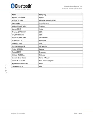
1.2 Profile Dependencies
In Figure 1.1, the Bluetooth profile structure and the dependencies of the profiles are depicted.
A profile is dependent upon another profile if it re-uses parts of that profile, by explicitly
referencing it. Dependency is illustrated in Figure 1.1.
Figure 1.1: Bluetooth Profiles
As indicated in Figure 1.1, the Hands-Free Profile is dependent upon both the Serial Port Profile
[5] and the Generic Access Profile [4]. Details are provided in Sections 5 (Serial Port Profile)
and 6 (Generic Access Profile).
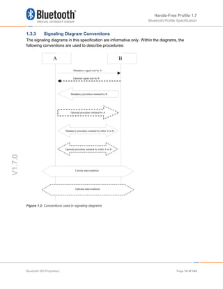
1.3 Symbols and Conventions
1.3.1 Requirement Status Symbols
In this document, the following symbols are used:
• "M" for mandatory to support
• "O" for optional to support
• "X" for excluded (used for capabilities that may be supported by the device, but the Hands-
Free Profile shall not use these capabilities)
• "C" for conditional to support
• "N/A" for not applicable (in the given context this capability is not defined)
Some capabilities or features (identified as “X”), mandated according to the relevant Bluetooth
specifications, are excluded with respect to this profile because they may degrade the operation
of devices in the particular use case. Therefore, features or capabilities labeled “X” shall never
be activated while operating in a use case where they are labeled as such.
SCO and
eSCO (Audio)
Hands-Free Profile (HFP)
Generic Access
Profile (GAP)
Service Discovery
Protocol (SDP)
Serial Port Profile (SPP)
RFCOMM
AT CMD
Logical Link and Adapation Layer (L2CAP)
Controller(s)
Host Controller Interface (HCI)
Bluetooth SIG Proprietary Page 12 of 144](https://image.slidesharecdn.com/hfpv1-210828232930/85/Hands-Free-Profile-1-7-12-320.jpg)
![Hands-Free Profile 1.7
Bluetooth Profile Specification
V1.7.0
1.3.2 Naming Conventions
In this document, the following naming conventions are used:
Where “Core Specification” is said it refers to the Bluetooth Core Specification v2.0 + EDR or
later adopted by the Bluetooth SIG.
Where “LMP link” is said, it means a Link Manager (LM) level link over which only Link Manager
Protocol (LMP) commands are conveyed.
Where “RFCOMM connection” is said, it means the presence of a virtual serial port as specified
in [6].
• Where “Service Level Connection” is said, it means a synchronized high-level protocol
connection involving a portion of the protocol stack. In this specific case, it refers to the
presence of a RFCOMM connection, and assumes that the HF has synchronized itself to the
state of the AG using the specified Service Level Connection initialization procedure.
• Where “Service Level Connection initialization” is said, it means the execution of the set of
AT commands and responses specified by the profile necessary to synchronize the state of
the HF with that of the AG.
• Where “Service Level Connection establishment” is said, it means the combined process of
establishing the RFCOMM connection, as well as the necessary device synchronization
using Service Level Connection initialization.
• Where “Synchronous Connection” is said, it means a SCO or eSCO logical link intended for
supporting a full duplex Audio Connection.
• Where “Audio Connection” is said, it means a Synchronous Connection including the means
to provide a complete audio path between two devices assuming roles within this profile.
• Where “Codec Connection” is said, it means a Synchronous Connection established after
profile level negotiation of Codec and related configuration.
• Where “Wide Band Speech Connection” is said, it means a Codec Connection where the
media being transported consists of encoded frames derived from speech (or other audio)
sampled at 16 kHz. The format of the media transported over the Synchronous Connection
shall be negotiated during the establishment of the Codec Connection.
• Where “mSBC” or “Modified SBC” is said, it means a modified version of the A2DP SBC
codec that is used as the mandatory codec for Wide Band Speech Connections. Section
5.7.4 contains a complete definition of the modifications which comprise mSBC.
• Where “incoming call” is said, it means a call connection in the direction “Phone
Network=>AG”, such that it is initiated by the Network to which the AG is attached.
• Where ‘outgoing call’ is said, it means a call connection in the direction ”AG=>Phone
Network”, such that it is initiated by the AG towards the Network to which it is attached.
• Where ‘legacy device’ is said, it means a device that is compatible with an earlier version,
v0.96, v1.0 or v1.5, of this specification; see Section 5.3.2.
Bluetooth SIG Proprietary Page 13 of 144](https://image.slidesharecdn.com/hfpv1-210828232930/85/Hands-Free-Profile-1-7-13-320.jpg)
![Hands-Free Profile 1.7
Bluetooth Profile Specification
V1.7.0
2 Profile Overview
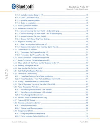
2.1 Protocol Stack
Figure 2.1 shows the protocols and entities used in this profile.
Figure 2.1: Protocol stack
The Baseband, LMP and L2CAP are the OSI layer 1 and 2 Bluetooth protocols. RFCOMM is the
Bluetooth serial port emulation entity. SDP is the Bluetooth Service Discovery Protocol. See [1]
for more details on these topics.
Compatibility to v1.1 or later Core Specification is required.
Hands-Free control is the entity responsible for Hands-Free unit specific control signaling; this
signaling is AT command based.
Although not shown in the model above, it is assumed by this profile that Hands-Free Control
has access to some lower layer procedures (for example, Synchronous Connection
establishment).
The audio port emulation layer shown in Figure 2.1 is the entity emulating the audio port on the
Audio Gateway, and the audio driver is the driver software in the Hands-Free unit.
For the shaded protocols/entities in Figure 2.1, the Serial Port Profile [5] is used as the base
standard. For these protocols, all mandatory requirements stated in the Serial Port Profile apply
except in those cases where this specification explicitly states deviations.
Baseband
LMP L2CAP
RFCOMM
Application
(Audio port emulation)
Baseband
LMP
RFCOMM
Hands-Free control
SDP SDP
L2CAP
Audio Gateway side Hands-Free side
Hands-Free control
Application
(Audio driver)
Bluetooth SIG Proprietary Page 15 of 144](https://image.slidesharecdn.com/hfpv1-210828232930/85/Hands-Free-Profile-1-7-15-320.jpg)

![Hands-Free Profile 1.7
Bluetooth Profile Specification
V1.7.0
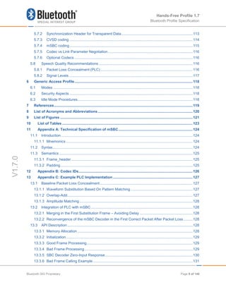
2.4 Profile Fundamentals
If a LMP link is not already established between the Hands-Free unit and the Audio Gateway,
the LMP link shall be set up before any other procedure is performed.
There are no fixed master or slave roles in the profile.
The Audio Gateway and Hand-Free unit provide serial port emulation. For the serial port
emulation, RFCOMM (see [1]) is used. The serial port emulation is used to transport the user
data including modem control signals and AT command from the Hands-Free unit to the Audio
Gateway. The AT commands are parsed by the Audio Gateway and responses are sent to the
Hands-Free unit via the Bluetooth serial port connection.
2.5 Conformance
If conformance to this profile is claimed, all capabilities indicated as mandatory for this profile
shall be supported in the specified manner (process mandatory). This also applies for all
optional and conditional capabilities for which support is indicated. Devices that claim
compliance to this profile shall not have a dependency on any other profiles and protocols
beyond what is specified in Section 2.1. All mandatory, optional and conditional capabilities, for
which support is indicated, are subject to verification as part of the Bluetooth Qualification
Program.”
Bluetooth SIG Proprietary Page 17 of 144](https://image.slidesharecdn.com/hfpv1-210828232930/85/Hands-Free-Profile-1-7-17-320.jpg)


![Hands-Free Profile 1.7
Bluetooth Profile Specification
V1.7.0
4 Hands-Free Control Interoperability Requirements
4.1 Introduction
The interoperability requirements for the Hands-Free Control entity are completely contained in
this section. Sections 4.2 through 4.28 specify the requirements for the procedures directly
related to the application layer features.
The procedures listed in this section are primarily based on the use of a minimum set of AT
commands as the control protocol. Section 4.33 specifies these AT commands and their result
codes.
Section 4.2 specifies how Service Level Connections are handled in general and specifically
states how the layers beneath the Hands-Free Control entity are used to establish and release a
Service Level Connection.
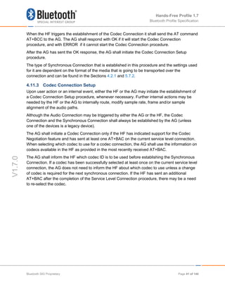
4.2 Service Level Connection Establishment
Upon a user action or an internal event, either the HF or the AG may initiate a Service Level
Connection establishment procedure.
A Service Level Connection establishment requires the existence of a RFCOMM connection,
that is, a RFCOMM data link channel between the HF and the AG.
Both the HF and the AG may initiate the RFCOMM connection establishment. If there is no
RFCOMM session between the AG and the HF, the initiating device shall first initialize
RFCOMM.
The RFCOMM connection establishment shall be performed as described in Section 7.3 of
Generic Access Profile [5] and Section 3 of Serial Port Profile [6].
4.2.1 Service Level Connection Initialization
When an RFCOMM connection has been established, the Service Level Connection
Initialization procedure shall be executed.
4.2.1.1 Supported features exchange
First, in the initialization procedure, the HF shall send the AT+BRSF=<HF supported features>
command to the AG to both notify the AG of the supported features in the HF, as well as to
retrieve the supported features in the AG using the +BRSF result code.1
4.2.1.2 Codec Negotiation
Secondly, in the initialization procedure, if the HF supports the Codec Negotiation feature, it
shall check if the AT+BRSF command response from the AG has indicated that it supports the
Codec Negotiation feature. If both the HF and AG do support the Codec Negotiation feature
1
Audio Gateways supporting the 0.96 version of Hands-Free Profile will return ERROR as a response to AT+BRSF
Bluetooth SIG Proprietary Page 23 of 144](https://image.slidesharecdn.com/hfpv1-210828232930/85/Hands-Free-Profile-1-7-23-320.jpg)
![Hands-Free Profile 1.7
Bluetooth Profile Specification
V1.7.0
then the HF shall send the AT+BAC=<HF available codecs> command to the AG to notify the
AG of the available codecs in the HF.2
4.2.1.3 AG Indicators
After having retrieved the supported features in the AG, the HF shall determine which indicators
are supported by the AG, as well as the ordering of the supported indicators. This is because,
according to the 3GPP 27.007 specification [2], the AG may support additional indicators not
provided for by the Hands-Free Profile, and because the ordering of the indicators is
implementation specific. The HF uses the AT+CIND=? Test command to retrieve information
about the supported indicators and their ordering.
Once the HF has the necessary supported indicator and ordering information, it shall retrieve
the current status of the indicators in the AG using the AT+CIND? Read command.
After having retrieved the status of the indicators in the AG, the HF shall then enable the
"Indicators status update" function in the AG by issuing the AT+CMER command, to which the
AG shall respond with OK. As a result, the AG shall send the +CIEV unsolicited result code with
the corresponding indicator value whenever a change in service, call, or call setup status
occurs. When an update is required for both the call and call setup indicators, the AG shall send
the +CIEV unsolicited result code for the call indicator before sending the +CIEV unsolicited
result code for the call setup indicator. The HF shall use the information provided by the +CIEV
code to update its own internal and/or external indications.
Once the "Indicators status update" function has been enabled, the AG shall keep the function
enabled until either the AT+CMER command is issued to disable it, or the current Service Level
Connection between the AG and the HF is dropped for any reason.
After the HF has enabled the “Indicators status update” function in the AG, and if the “Call
waiting and 3-way calling” bit was set in the supported features bitmap by both the HF and the
AG, the HF shall issue the AT+CHLD=? test command to retrieve the information about how the
call hold and multiparty services are supported in the AG. The HF shall not issue the
AT+CHLD=? test command in case either the HF or the AG does not support the "Three-way
calling" feature.
4.2.1.4 HF Indicators
If the HF supports the HF indicator feature, it shall check the +BRSF response to see if the AG
also supports the HF Indicator feature.
If both the HF and AG support the HF Indicator feature, then the HF shall send the
AT+BIND=<HF supported HF indicators> command to the AG to notify the AG of the supported
indicators’ assigned numbers in the HF. The AG shall respond with OK.
2
Legacy devices shall not indicate support for the Codec Negotiation Feature
Bluetooth SIG Proprietary Page 24 of 144](https://image.slidesharecdn.com/hfpv1-210828232930/85/Hands-Free-Profile-1-7-24-320.jpg)


![Hands-Free Profile 1.7
Bluetooth Profile Specification
V1.7.0
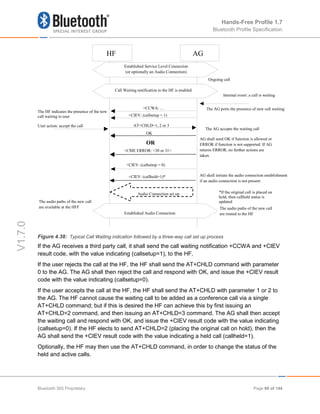
+CCWA unsolicited result code to the HF whenever an incoming call is waiting during an
ongoing call. It is always assumed that the “call waiting” service is already active in the network.
Once the HF issues the AT+CCWA command, the AG shall respond with OK. It shall then keep
the “Call Waiting notification” enabled until either the AT+CCWA command is issued to disable
“Call Waiting notification,” or the current Service Level Connection between the AG and the HF
is dropped for any reason.
See Section 4.33 for more information on the AT+CCWA command.
Apreconditions a precondition for this procedure, an ongoing Service Level Connection between
the AG and the HF shall exist. If this connection does not exist, the HF shall autonomously
establish the Service Level Connection using the proper procedure as described in Section 4.2.
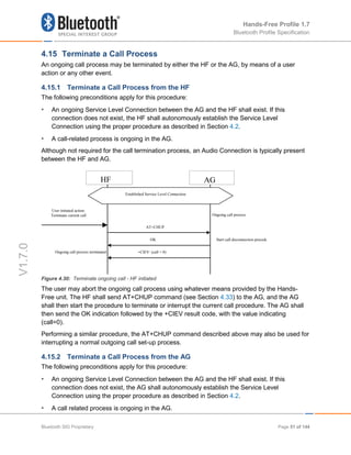
Figure 4.37: Activation of Call waiting notification
4.22 Three-Way Call Handling
Proper management of several concurrent calls shall be accomplished by performing the
procedures described in [2] but with some limitations stated in this specification. For more
details, refer to Section 4.33.
The HF device cannot always assume that the "call hold and/or multiparty" services are
available in the network. If the AG determines that a requested action by the HF device cannot
be performed due to the inability of the network to support that feature or lack of subscriber
subscription, the AG shall return a +CME error.
There are two +CME ERROR codes that are used to indicate network related failure reasons to
the HF:
30 - No Network Service. Indicates that an AT+CHLD command cannot be implemented due to
network limitations.
31 - Network Timeout. Indicates that an AT+CHLD command cannot be implemented due to
network problems.
HF AG
AT+CCWA=1
Internal event or user requested:
Enable Call Waiting notification
The AG enables the Call Waitin
OK
The HF requests enabling Call
Waiting notification indication
Established Service Level Connection
Bluetooth SIG Proprietary Page 58 of 144](https://image.slidesharecdn.com/hfpv1-210828232930/85/Hands-Free-Profile-1-7-58-320.jpg)


![Hands-Free Profile 1.7
Bluetooth Profile Specification
V1.7.0
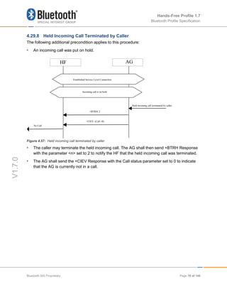
• If the HF has enabled the Calling Line Identification [CLI], the AG shall send a +CLIP
Response to HF.
• The user may put the incoming voice call on hold by using the proper means provided by
the HF. The HF shall then send the AT+BTRH command with the parameter <n> set to 0.
The AG shall then begin the procedure for putting the incoming call on hold.
• The AG shall send +BTRH Response with the parameter set to 0 as soon as the incoming
call is put on hold.
• The +CIEV: (callheld = 2) message shall not be sent when a call is held via the AT+BTRH=0
message.
• The AG shall send the +CIEV Response with the call status set to 1.
• The AG shall send the +CIEV Response with the callsetup status set to 0.
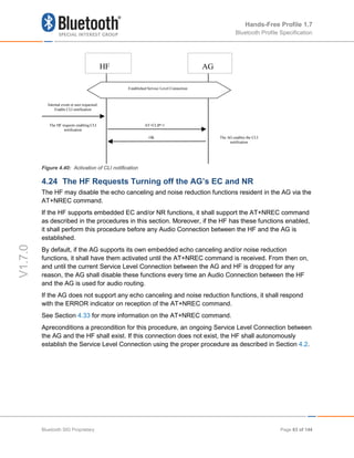
4.29.3 Put an Incoming Call on Hold from AG
Figure 4.52: Put an incoming call on Hold from AG
As a precondition to this procedure, the AG shall not have an active call or a call on hold.
• The AG shall send a sequence of unsolicited RING alerts to the HF. The RING alert shall be
repeated until the HF accepts the incoming call or until the incoming call is interrupted for
any reason.
HF AG
RING
RING Repeated Alerting
User initiated action;
Put the incoming call on Hold
Incoming call
+BTRH: 0
Established Service Level Connection
…
+CLIP…
+CLIP…
The HF alerts the user
+CIEV: (callsetup=0)
+CIEV: (call =1)
Call Active
On Hold
+CIEV: (callsetup=1)
Bluetooth SIG Proprietary Page 73 of 144](https://image.slidesharecdn.com/hfpv1-210828232930/85/Hands-Free-Profile-1-7-73-320.jpg)
![Hands-Free Profile 1.7
Bluetooth Profile Specification
V1.7.0
• If the HF has enabled the Calling Line Identification [CLI], the AG shall send a +CLIP
Response to the HF.
• The user may put the incoming voice call on hold by using the proper means provided by
the AG unit. The AG shall then send +BTRH Response with the parameter <n> set to 0 to
indicate that the incoming call is on hold.
• The +CIEV: (callheld = 2) message shall NOT be sent by the audio gateway when it holds a
call via the response and hold method.
• Depending on whether in-band ringing is enabled or disabled, there may or may not be a
synchronous connection established between the HF and AG. The synchronous connection
state (enabled or disabled) shall not be changed when an incoming call is placed on hold.
• The AG shall send the +CIEV Response with the call status set to 1.
• The AG shall send the +CIEV Response with the callsetup status set to 0.
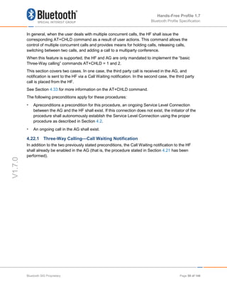
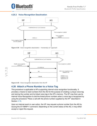
4.29.4 Accept a Held Incoming Call from HF
The following additional precondition applies to this procedure:
• An incoming call was put on hold.
Figure 4.53: Accept a held incoming call from HF
• The user may accept the incoming voice call on hold by using the proper means provided by
the HF. The HF shall then send the AT+BTRH command with the parameter <n> set to 1.
The AG shall then begin the procedure for accepting the incoming call that was put on hold.
HF AG
AT+BTRH=1
Internal event or user requested:
Accept held incoming call
The AG accepts the held
incoming call
OK
Incoming call is on hold
+BTRH: 1
Audio connection set up
AG shall initiate the audio
connection establishment
if an audio connection is
not present
Established Service Level Connection
Bluetooth SIG Proprietary Page 74 of 144](https://image.slidesharecdn.com/hfpv1-210828232930/85/Hands-Free-Profile-1-7-74-320.jpg)


![Hands-Free Profile 1.7
Bluetooth Profile Specification
V1.7.0
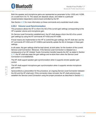
4.30 Subscriber Number Information
This procedure allows HF to query the AG subscriber number.
Figure 4.58: Query Subscriber Number Information of AG
This procedure illustrates AG response to the query of an empty subscriber number.
Figure 4.59: Empty Subscriber Number Information from AG
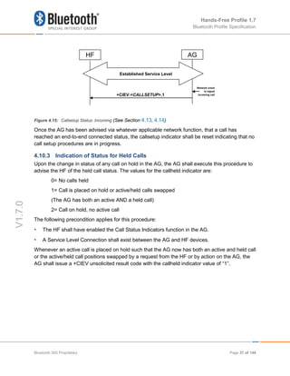
The following precondition applies for this procedure:I'
• An ongoing Service Level Connection between the HF and AG shall exist. If this connection
does not exist, the HF shall establish a connection using the “Service Level Connection set
up” procedure described in Section 4.2.
• The HF shall send the AT+CNUM command to query the AG subscriber number
information.
HF AG
HF sends command to get
the Subscriber Number
Information
AT+CNUM
+CNUM: ,<number>,<type>[,, <service>] AG sends Subscriber
Number Information
OK
+CNUM: ,<number>,<type>[,, <service>]
. . .
Established Service Level Connection
HF AG
HF sends command to get
the Subscriber Number
Information
AT+CNUM
OK
Established Service Level Connection
Bluetooth SIG Proprietary Page 79 of 144](https://image.slidesharecdn.com/hfpv1-210828232930/85/Hands-Free-Profile-1-7-79-320.jpg)
![Hands-Free Profile 1.7
Bluetooth Profile Specification
V1.7.0
• If the subscriber number information is available, the AG shall respond with the +CNUM
response. If multiple numbers are available, the AG shall send a separate +CNUM response
for each available number.
• The AG shall signal the completion of the AT+CNUM action command with an OK response.
The OK will follow zero or more occurrences of the +CNUM response. (See Figure 4.55 and
Figure 4.56).
4.31 Enhanced Call Status Mechanisms
4.31.1 Query List of Current Calls in AG
The HF shall execute this procedure to query the list of current calls in AG.
The following precondition applies for this procedure:
• A Service Level Connection must exist between the AG and HF devices. If no current
Service Level Connection exists, the HF shall first initiate one.
Figure 4.60: Query List of Current Calls
• HF shall find out the list of current calls in AG by sending the AT+CLCC command.
• If the command succeeds and if there is an outgoing (Mobile Originated) or an incoming
(Mobile Terminated) call in AG, AG shall send a +CLCC response with appropriate
parameters filled in to HF.
• If there are no calls available, no +CLCC response is sent to HF.
• The AG shall always send OK response to HF.
HF AG
+CLCC:
<idx>,<dir>,<status>,<mode>,<mprty>[,<number>,<type>] The AG reports the list
of current calls
AT+CLCC
OK
The HF queries the current
list of current calls in AG
+CLCC:
<idx>,<dir>,<status>,<mode>,<mprty>[,<number>,<type>]
Established Service Level Connection
Bluetooth SIG Proprietary Page 80 of 144](https://image.slidesharecdn.com/hfpv1-210828232930/85/Hands-Free-Profile-1-7-80-320.jpg)

![Hands-Free Profile 1.7
Bluetooth Profile Specification
V1.7.0
• Existing multiparty call is active in AG.
Figure 4.62 Request Private Consultation Mode
• HF shall send the AT+CHLD=2<idx> command to request private consultation mode.
• AG shall place all other parties of call on hold.
• AG shall report the change in status of the held parties.
• If the index (<idx>) is not valid, the AG shall respond with the proper error code.
4.33 AT Command and Results Codes
4.33.1 General
For the exchange of the commands and unsolicited results codes, the format, syntax and
procedures of 3GPP 27.007 [2] shall be taken as reference. The following rules specifically
apply for the HFP specification:
• Only one command (or unsolicited result code) per command line needs to be expected.
• The AG, by default, shall not echo the command characters.
• The AG shall always transmit result codes using verbose format.
• The characters below shall be used for AT commands and result codes formatting:
<cr> corresponds to the carriage return (0/13) as stated in [7].
<lf> corresponds to the line feed (0/10) as stated in [7].
• The format of an AT command from the HF to the AG shall be:
<AT command><cr>
• The format of the OK code from the AG to the HF shall be:
AG reports change in
call status for HELD
calls.
HF AG
+CIEV: < CallHeld Indicator >,1
AT+CHLD=2<idx>
HF request
private
consultation
mode.
Existing multiparty call
AG places ALL parties of
multiparty call on hold,
except specified call
OK
Established Service Level Connection
Bluetooth SIG Proprietary Page 82 of 144](https://image.slidesharecdn.com/hfpv1-210828232930/85/Hands-Free-Profile-1-7-82-320.jpg)
![Hands-Free Profile 1.7
Bluetooth Profile Specification
V1.7.0
<cr><lf>OK<cr><lf>
• The format of the generic ERROR code from the AG to the HF shall be:
<cr><lf>ERROR<cr><lf>
• The format of an unsolicited result code from the AG to the HF shall be:
<cr><lf><result code><cr><lf>
The Hands-Free Profile uses a subset of AT commands and result codes from existing
standards; these are listed in Section 4.33.2. Section 4.34 lists the new Bluetooth defined AT
commands and result codes not re-used from any existing standard.
In general, the AG shall use the OK code, as described in Section 4.33.2, for acknowledgement
of the proper execution of a command and respond with the proper error indication to any
unknown command received from the HF.
It is mandatory for the AG to properly respond to any error condition and for the HF to properly
process the corresponding error indication code received from the AG. The code ERROR, as
described in Section 4.33.2, shall be used as error indication for this purpose.
The HF shall always ignore any unknown or unexpected indication code received from the AG.
The only exception is the case in which the AG issues a “Mobile Equipment Error” indication
using the +CME ERROR: result code (see [2]). In this case, the HF shall interpret this result
code in the same way as if it was a generic ERROR code.
As a general rule, when an AT command or result code of this specification is implemented,
support for the associated parameters “covered” in this specification, and all their corresponding
possible values, shall be considered mandatory unless otherwise explicitly stated in each
particular case.
4.33.2 AT Capabilities Re-Used from GSM 07.07 and 3GPP 27.007
The re-used AT commands and unsolicited result codes for implementing the functionality
described in this specification are listed below:
As a convention, if a parameter of an AT command or result code is not “covered” in this
specification, it shall not be present in the corresponding AT command, and the HF shall ignore
the parameter whenever it is received in a result code.
• ATA
Standard call answer AT command. See Annex G in [2].
• ATDdd…dd;
Standard AT command intended for placing a call to a phone number. Only voice calls are
covered in this specification. See Section 6.2 in [2].
• ATD>nnn...;
Bluetooth SIG Proprietary Page 83 of 144](https://image.slidesharecdn.com/hfpv1-210828232930/85/Hands-Free-Profile-1-7-83-320.jpg)
![Hands-Free Profile 1.7
Bluetooth Profile Specification
V1.7.0
Extension of the standard ATD command, intended for memory dialing. Only voice calls are
covered in this specification. See Section 6.3 in [2].
• ERROR
Standard error indication code. It shall be issued on detection of any syntax, format or
procedure error condition. The “Mobile Equipment Error” report code “+CME ERROR:” is
covered below. See Annex B in [2].
• OK
Standard acknowledgement to the execution of a command. See Annex B in [2].
• NO CARRIER, BUSY, NO ANSWER, DELAYED, BLACKLISTED
Extended response indication codes for AT commands. These codes shall be issued from
the AG to the HF as responses to AT commands from the HF to the AG or from the AG as
unsolicited result codes. These are in addition to the +CME ERROR: responses.
• RING
Standard “incoming call” indication. See Annex B in [2].
• AT+CCWA
Standard “Call Waiting notification” AT command. Within the
AT+CCWA=[<n>[,<mode>[,<class>]]]command, only enabling/disabling of the Call Waiting
notification unsolicited result code +CCWA , using the <n> parameter, is covered in this
specification. See Section 7.12 in [2].
• +CCWA
Standard “Call Waiting notification” unsolicited result code.
In the +CCWA result code only <number> and <type> parameters are covered in this
specification. Other parameters are not considered relevant in this specification and shall be
ignored by the HF.
The <number> parameter shall be a text string and shall always be contained within double-
quotes.
The <type> field specifies the format of the phone number provided, and can be one of the
following values:
values 128-143: The phone number format may be a national or international format, and
may contain prefix and/or escape digits. No changes on the number presentation are
required.
values 144-159: The phone number format is an international number, including the country
code prefix. If the plus sign ("+") is not included as part of the number and shall be added by
the AG as needed.
values 160-175: National number. No prefix nor escape digits included.
Bluetooth SIG Proprietary Page 84 of 144](https://image.slidesharecdn.com/hfpv1-210828232930/85/Hands-Free-Profile-1-7-84-320.jpg)
![Hands-Free Profile 1.7
Bluetooth Profile Specification
V1.7.0
See Section 7.12 in [2].
AT+CHLD
Standard call hold and multiparty handling AT command. In the AT+CHLD=<n> command,
this specification only covers values for <n> of 0, 1, 1<idx>, 2, 2<idx>, 3 and 4, where:
- 0 = Releases all held calls or sets User Determined User Busy (UDUB) for a waiting call.
- 1 = Releases all active calls (if any exist) and accepts the other (held or waiting) call.
- 1<idx> = Releases specified active call only (<idx>).
- 2 = Places all active calls (if any exist) on hold and accepts the other (held or waiting)
call.
- 2<idx> = Request private consultation mode with specified call (<idx>). (Place all calls
on hold EXCEPT the call indicated by <idx>.)
- 3 = Adds a held call to the conversation.
- 4 = Connects the two calls and disconnects the subscriber from both calls (Explicit Call
Transfer). Support for this value and its associated functionality is optional for the HF.
- Where both a held and a waiting call exist, the above procedures shall apply to the
waiting call (i.e., not to the held call) in conflicting situation.
The test command AT+CHLD=? may be used for retrieving information about the call hold
and multiparty services available in the AG (see Section 4.2.1).
See Section 7.13 in [2] and Section 4.5.5.1 in [8] for details.
• AT+CHUP
Standard hang-up AT command. Execution command causes the AG to terminate the
currently active call. This command shall have no impact on the state of a held call except in
the use of rejecting a call placed on hold by the Respond and Hold feature as defined in
Section 4.29.6.
See Section 6.5 in [2].
AT+CHUP is also used as the command to reject any incoming call prior to answer.
• AT+CIND
Standard indicator update AT command. Only read command AT+CIND? and test command
AT+CIND=? are required in this specification.
The AT+CIND? read command is used to get current status of the AG indicators.
The AG shall return all the indicators listed in the AT+CIND=? command.
The deactivation of any indicator(s) using AT+BIA command shall have no effect on the
AG’s response to the AT+CIND? read command.
Bluetooth SIG Proprietary Page 85 of 144](https://image.slidesharecdn.com/hfpv1-210828232930/85/Hands-Free-Profile-1-7-85-320.jpg)
![Hands-Free Profile 1.7
Bluetooth Profile Specification
V1.7.0
The AT+CIND=? test command is used to retrieve the mapping between each indicator
supported by the AG and its corresponding range and order index. It shall be issued at least
once before any other command related to these indicators (AT+CIND? or AT+CMER) is
used.
The Hands Free Profile specification limits the number of indicators returned by the AG to a
maximum of 20.
The following indicators are covered in this specification:
- service: Service availability indication, where:
<value>=0 implies no service. No Home/Roam network available.
<value>=1 implies presence of service. Home/Roam network available.
- call: Standard call status indicator, where:
<value>=0 means there are no calls in progress
<value>=1 means at least one call is in progress
- callsetup: Bluetooth proprietary call set up status indicator4
. Support for this indicator is
optional for the HF. When supported, this indicator shall be used in conjunction with, and
as an extension of the standard call indicator. Possible values are as follows:
<value>=0 means not currently in call set up.
<value>=1 means an incoming call process ongoing.
<value>=2 means an outgoing call set up is ongoing.
<value>=3 means remote party being alerted in an outgoing call.
See Section 8.9 in [2].
- callheld: Bluetooth proprietary call hold status indicator. Support for this indicator is
mandatory for the AG, optional for the HF. Possible values are as follows:
0= No calls held
1= Call is placed on hold or active/held calls swapped
(The AG has both an active AND a held call)
2= Call on hold, no active call
- signal: Signal Strength indicator, where:
<value>= ranges from 0 to 5
- roam: Roaming status indicator, where:
<value>=0 means roaming is not active
4
This status indicator is not defined in the GSM 07.07 specification
Bluetooth SIG Proprietary Page 86 of 144](https://image.slidesharecdn.com/hfpv1-210828232930/85/Hands-Free-Profile-1-7-86-320.jpg)
![Hands-Free Profile 1.7
Bluetooth Profile Specification
V1.7.0
<value>=1 means a roaming is active
- battchg: Battery Charge indicator of AG, where:
<value>=ranges from 0 to 5
• +CIND
Standard list of current phone indicators. See Section 8.9 in [2].
• AT+CLCC
Standard list current calls command. See Section 7.18 in [2].
• +CLCC
Standard list current calls result code. See Section 7.18 in [2].
Supported parameters are as follows:
- idx= The numbering (starting with 1) of the call given by the sequence of setting up or
receiving the calls (active, held or waiting) as seen by the served subscriber. Calls hold
their number until they are released. New calls take the lowest available number.
- dir= 0 (outgoing), 1 (incoming)
- status=
o 0 = Active
o 1 = Held
o 2 = Dialing (outgoing calls only)
o 3 = Alerting (outgoing calls only)
o 4 = Incoming (incoming calls only)
o 5 = Waiting (incoming calls only)
o 6 = Call held by Response and Hold
- mode= 0 (Voice), 1 (Data), 2 (FAX)
- mpty=
o 0 - this call is NOT a member of a multi-party (conference) call
o 1 - this call IS a member of a multi-party (conference) call
- number (optional)
- type (optional)
• AT+COPS
The AT+COPS=3,0 shall be sent by the HF to the AG prior to sending the AT+COPS?
command. AT+COPS=3,0 sets the format of the network operator string to the long format
alphanumeric.
Bluetooth SIG Proprietary Page 87 of 144](https://image.slidesharecdn.com/hfpv1-210828232930/85/Hands-Free-Profile-1-7-87-320.jpg)
![Hands-Free Profile 1.7
Bluetooth Profile Specification
V1.7.0
The AT+COPS? command is used for reading network operator. This profile shall only
support the "reading" of the name of the network operator. The response to this command
from the AG shall return a +COPS:<mode>,<format>,<operator> where:
<mode> contains the current mode and provides no information with regard to the name of
the operator.
<format> specifies the format of the <operator> parameter string, and shall always be 0 for
this specification.
<operator> specifies a quoted string in alphanumeric format representing the name of the
network operator. This string shall not exceed 16 characters. See Section 7.3 in [2].
• AT+CMEE
Standard AT command used to enable the use of result code +CME ERROR: <err> as an
indication of an error relating to the functionality of the AG.
The set command AT+CMEE=1 is covered in this specification.
• +CME ERROR
This is the Extended Audio Gateway Error Result Code response. Format of the response
is: +CME ERROR: <err>. The format of <err> shall be numeric in this specification. The
possible values for <err> covered in this specification are described below. These error
codes may be provided instead of the standard ERROR response code to provide additional
information to the HF. The ERROR response code is still allowed while using the Extended
Audio Gateway Error Result Codes.
+CME ERROR: 0 – AG failure
+CME ERROR: 1 – no connection to phone
+CME ERROR: 3 – operation not allowed
+CME ERROR: 4 – operation not supported
+CME ERROR: 5 – PH-SIM PIN required
+CME ERROR: 10 – SIM not inserted
+CME ERROR: 11 – SIM PIN required
+CME ERROR: 12 – SIM PUK required
+CME ERROR: 13 – SIM failure
+CME ERROR: 14 – SIM busy
+CME ERROR: 16 – incorrect password
+CME ERROR: 17 – SIM PIN2 required
+CME ERROR: 18 – SIM PUK2 required
+CME ERROR: 20 – memory full
Bluetooth SIG Proprietary Page 88 of 144](https://image.slidesharecdn.com/hfpv1-210828232930/85/Hands-Free-Profile-1-7-88-320.jpg)
![Hands-Free Profile 1.7
Bluetooth Profile Specification
V1.7.0
+CME ERROR: 21 – invalid index
+CME ERROR: 23 – memory failure
+CME ERROR: 24 – text string too long
+CME ERROR: 25 – invalid characters in text string
+CME ERROR: 26 – dial string too long
+CME ERROR: 27 – invalid characters in dial string
+CME ERROR: 30 – no network service
+CME ERROR: 31 - network Timeout.
+CME ERROR: 32 – network not allowed – Emergency calls only
• AT+CLIP
Standard “Calling Line Identification notification” activation AT command. It enables/disables
the Calling Line Identification notification unsolicited result code +CLIP. See Section 7.6 in
[2].
• +CLIP
Standard “Calling Line Identification notification” unsolicited result code.
In the +CLIP: <number>, type> [,<subaddr>,<satype> [,[<alpha>] [,<CLI validity>]]] result
code. Only <number> and <type> parameters are covered in this specification. Other
parameters are not considered relevant in this specification and shall be ignored by the HF.
The <number> parameter shall be a text string and shall always be contained within double-
quotes.
The <type> field specifies the format of the phone number provided, and can be one of the
following values:
- values 128-143: The phone number format may be a national or international format,
and may contain prefix and/or escape digits. No changes on the number presentation
are required.
- values 144-159: The phone number format is an international number, including the
country code prefix. If the plus sign ("+") is not included as part of the number and shall
be added by the AG as needed.
- values 160-175: National number. No prefix nor escape digits included.
- See Section 7.11 in [2].
• AT+CMER
Standard event reporting activation/deactivation AT command.
Bluetooth SIG Proprietary Page 89 of 144](https://image.slidesharecdn.com/hfpv1-210828232930/85/Hands-Free-Profile-1-7-89-320.jpg)
![Hands-Free Profile 1.7
Bluetooth Profile Specification
V1.7.0
In the AT+CMER=[<mode>[,<keyp>[,<disp>[,<ind> [,<bfr>]]]]] command, only the <mode>,
and <ind> parameters are relevant for this specification. Only their values <mode>=(3) and
<ind>=(0,1) are covered in this specification. See Section 8.10 in [2].
The following examples show how the AT+CMER command may be used for activating or
deactivating the “indicator events reporting” result code:
AT+CMER=3,0,0,1 activates “indicator events reporting”.
AT+CMER=3,0,0,0 deactivates “indicator events reporting”.
• +CIEV
Standard “indicator events reporting” unsolicited result code.
In the +CIEV: <ind>,<value> result code, only the indicators stated in the AT+CIND
command above are relevant for this specification where:
- <ind>: Order index of the indicator within the list retrieved from the AG with the
AT+CIND=? command. The first element of the list shall have <ind>=1.
- <value>: current status of the indicator.
If the HF receives any unknown indicator or value, it shall ignore it.
See Section 8.10 in [2].
• AT+VTS
Standard DTMF generation AT command. Only the AT+VTS=<DTMF> command format is
covered in this specification.
See Annex C.2.11 in [2].
• AT+CNUM
Syntax:
AT+CNUM (Retrieve Subscriber Number Information)
AT+CNUM=? (Test Subscriber Number Information – Not Implemented)
Description:
Command issued by HF for the “Subscriber Number Information” feature in the AG.
Only the action command AT+CNUM format is used.
• +CNUM
Syntax:
+CNUM: [<alpha>],<number>, <type>,[<speed> ,<service>] (Response for AT+CNUM)
Description:
Standard Response used for sending the “Subscriber Number Information” from AG to
HF.
Bluetooth SIG Proprietary Page 90 of 144](https://image.slidesharecdn.com/hfpv1-210828232930/85/Hands-Free-Profile-1-7-90-320.jpg)
![Hands-Free Profile 1.7
Bluetooth Profile Specification
V1.7.0
The AG shall send the +CNUM: response for the AT+CNUM from the HF.
Values:
- <alpha>: This optional field is not supported, and shall be left blank.
- <number>: Quoted string containing the phone number in the format specified by
<type>.
- <type> field specifies the format of the phone number provided, and can be one of the
following values:
- values 128-143: The phone number format may be a national or international format,
and may contain prefix and/or escape digits. No changes on the number presentation
are required.
- values 144-159: The phone number format is an international number, including the
country code prefix. If the plus sign ("+") is not included as part of the number and shall
be added by the AG as needed.
- values 160-175: National number. No prefix nor escape digits included.
- <speed>: This optional field is not supported, and shall be left blank.
- <service>: Indicates which service this phone number relates to. Shall be either 4 (voice)
or 5 (fax).
Example:
+CNUM: ,"5551212",129,,4
See section 7.1 in [2].
Bluetooth SIG Proprietary Page 91 of 144](https://image.slidesharecdn.com/hfpv1-210828232930/85/Hands-Free-Profile-1-7-91-320.jpg)

![Hands-Free Profile 1.7
Bluetooth Profile Specification
V1.7.0
If the event reporting (CMER) is disabled and then re-enabled, the AG shall send only the
indicators that were activated by the most recently processed AT+BIA command, or all
indicators in the case where no AT+BIA was sent by the HF.
The AT+BIA command has no impact on the response to the “AT+CIND?” read command (See
Section 4.33.2 in [1]).
A restriction to the AT+BIA command applies to the indicators call, call status and held call. The
AG shall always consider these indicators activated, even if the HF requests their deactivation.
It is mandatory for the AG to support the AT+BIA command.
It is optional for the HF to support the AT+BIA command.
It is optional for HF device to use the AT+BIA command.
See Section 4.33 in [1] for more information on the AT+CMER (event reporting) command.
4.34.1 Bluetooth Defined AT Capabilities
The GSM 07.07 [2] format and syntax rules shall be taken as the reference for these
commands.
The new Bluetooth specific AT capabilities are listed below:
• AT+BIA (Bluetooth Indicators Activation)
Syntax: AT+BIA=[[<indrep 1>][,[<indrep 2>][,…[,[<indrep n>]]]]]]
Description:
Activates or deactivates the indicators individually. The mapping of the indicators is
given by the “AT+CIND=?” test command (See Section 4.33.2 in [1])
<indrep x>: reporting state of the indicator x. 1 to activate, 0 to deactivate.
If an indicator state is omitted between commas, the current reporting state of that
indicator shall not change. For example, if the HF sends the command “AT+BIA=,1,,0”
only the second and fourth indicators may be affected. The reporting state of indicators
one and three shall remain unchanged.
If the AG supports more indicators than the number of indicator-reporting-states
provided by the HF, the AG shall maintain the current reporting states of those
indicators. For example, if the AG supports five indicators and the HF sends the
command “AT+BIA=1,0,1“ then only the first three AG indicators may be affected by the
command.
Call, Call Setup, and Held Call indicators have been defined as mandatory indicators.
This implies that whatever the reporting state the HF gives, these indicators shall always
been kept activated by the AG.
The AG shall gracefully ignore any excess parameter(s) at the end.
The AG shall silently ignore a request to deactivate a mandatory indicator.
Bluetooth SIG Proprietary Page 93 of 144](https://image.slidesharecdn.com/hfpv1-210828232930/85/Hands-Free-Profile-1-7-93-320.jpg)
![Hands-Free Profile 1.7
Bluetooth Profile Specification
V1.7.0
The previous three points allow the HF to activate or deactivate all the indicators, except
the mandatory ones, by using a fixed string.
For example, if the maximum indicator count is 20:
All indicators can be set to active by using the fixed string:
AT+BIA=1,1,1,1,1,1,1,1,1,1,1,1,1,1,1,1,1,1,1,1
and to inactive (except for the always active ones) by using:
AT+BIA=0,0,0,0,0,0,0,0,0,0,0,0,0,0,0,0,0,0,0,0
The actual number of allowed indicators is defined by the AT+CIND command.
• AT+BINP (Bluetooth INPut)
Syntax: AT+BINP=<datarequest>
Expected response: +BINP: <dataresp1>…<datarespn>
Description:
Command used for requesting some specific data input from the AG5
. On reception of
this command the AG shall perform the proper actions such that the requested
information is sent back to the HF using the +BINP response.
The type of data the HF shall expect in the <dataresp> parameter returned by the AG
depends on the information requested in each case.
Only support for execution command is mandated. Neither the read nor test commands
are mandatory.
Values:
<datarequest>: 1, where
1 = Phone number corresponding to the last voice tag recorded in the HF.
<dataresp1..n>: Data parameters returned by the AG. Their contents depend on the
value of the <datarequest> parameter as follows:
<datarequest> value <dataresp> parameters
1 <Phone number>:
Phone number string (max. 32 digits). The format (type of address)
of the phone number string shall conform with the rules stated in
[7], sub-clause 10.5.4.7, for a value (in integer format) of the type
of address octet of 145, if dialing string includes international
access code character “+”, and for a value of 129 otherwise.
• AT+BLDN (Bluetooth Last Dialed Number)
5
AT+BINP was created with future extensibility in mind. While the Hands-Free Profile only specifies a <datarequest> value of 1 (i.e.,
phone number), future profiles may choose to add values for <datarequest> to support the retrieval of additional data from the AG.
Bluetooth SIG Proprietary Page 94 of 144](https://image.slidesharecdn.com/hfpv1-210828232930/85/Hands-Free-Profile-1-7-94-320.jpg)


![Hands-Free Profile 1.7
Bluetooth Profile Specification
V1.7.0
microphone gain of the AG; it simply indicates the current value of the microphone gain
in the HF.
Only support for execution command is mandated. Neither the read nor test commands
are mandatory.
Values:
<gain>: 0 -15, entered as integer values, where
0 = Minimum gain
15 = Maximum gain
• AT+VGS (Gain of Speaker)
Syntax: AT+VGS=<gain>
Description:
Command issued by the HF to report its current speaker gain level setting to the AG.
<gain> is a decimal numeric constant, relating to a particular (implementation
dependent) volume level controlled by the HF. This command does not change the
speaker gain of the AG; it simply indicates the current value of the speaker volume in the
HF.
Only support for execution command is mandated. Neither the read nor test commands
are mandatory.
Values:
<gain>: 0 -15, entered as integer values, where
0 = Minimum gain
15 = Maximum gain
• +VGM (Gain of Microphone)
Syntax: +VGM:<gain>
Description:
Unsolicited result code issued by the AG to set the microphone gain of the HF. <gain> is
a decimal numeric constant, relating to a particular (implementation dependent) volume
level controlled by the HF.
Due to the small inconsistency between the GSM standard [2]) and the current Headset
specification ([3]), the HF shall also accept the “=” symbol, in place of “:”, as a valid
separator for this unsolicited result code.
Values:
<gain>: 0 -15, integer values, where
0 = Minimum gain
Bluetooth SIG Proprietary Page 98 of 144](https://image.slidesharecdn.com/hfpv1-210828232930/85/Hands-Free-Profile-1-7-98-320.jpg)
![Hands-Free Profile 1.7
Bluetooth Profile Specification
V1.7.0
15 = Maximum gain
• +VGS (Gain of Speaker)
Syntax: +VGS:<gain>
Description:
Unsolicited result code issued by the AG to set the speaker gain of the HF. <gain> is a
decimal numeric constant, relating to a particular (implementation dependent) volume
level controlled by the HF.
Due to the small inconsistency between the GSM 07.07 standard ([2]) and the current
Headset specification [3]), the HF shall also accept the “=” symbol, in place of “:”, as
valid separator for this unsolicited result code.
Values:
<gain>: 0 -15, integer values, where
0 = Minimum gain
15 = Maximum gain
• +BSIR (Bluetooth Setting of In-band Ring tone)
Syntax: +BSIR: <bsir>
Description:
Unsolicited result code issued by the AG to indicate to the HF that the in-band ring tone
setting has been locally changed. The HF may react accordingly by changing its own
alert method.
Values:
<bsir>: 0 = the AG provides no in-band ring tone
1 = the AG provides an in-band ring tone
• AT+BTRH (Bluetooth Response and Hold Feature)
Syntax:
AT+BTRH=<n> (Set command)
AT+BTRH? (Read Current Status)
Description:
Command issued by the HF for the “Response and Hold” feature in the AG.
This specification defines the use of the set and read command. The AT+BTRH?
command shall be used by the HF to query the current “Response and Hold” state of the
AG.
Values:
Bluetooth SIG Proprietary Page 99 of 144](https://image.slidesharecdn.com/hfpv1-210828232930/85/Hands-Free-Profile-1-7-99-320.jpg)

![Hands-Free Profile 1.7
Bluetooth Profile Specification
V1.7.0
This command informs the codec to the remote device (HF), and implicitly also which
synchronization protocol, will be used on the synchronous connection.
Values:
<u>: All possible Codec IDs, see definition of AT+BAC.
• AT+BAC (Bluetooth Available Codecs)
Syntax: AT+BAC= [<u1>[,<u2>[,...[,<un>]]]] (u1,u2, ..., un are a codec IDs)
Description:
This command informs the remote device (AG) about what codecs (see Table 3.3) the
HF supports.
The Codec ID for the mandatory narrow band codec (CVSD) shall always be included.
If wide band speech is supported, then the mandatory codec (mSBC) shall be included
unless it is temporarily unavailable.
Any other optional wide band speech codecs may also be included in this list as long as
the mandatory codec is included first.
Values:
<u>: All possible Codec IDs. Codec IDs shall be transferred as string representations of
decimal numbers. The format of the Codec IDs is 8 bit aliases that are defined in Section
12 (Appendix B: Codec IDs). For a single codec with ID=12 and the mandatory default
codecs (1 and 2), the command:
AT+BAC=1,2,12
is sent.
• AT+BIND (Bluetooth HF Indicators Feature)
Syntax:
AT+BIND= <a>,<b>,<c>,...,<n> (List HF supported indicators)
AT+BIND=? (Read AG supported indicators)
AT+BIND? (Read AG enabled/disabled status of indicators)
Description:
This command enables the HF to notify the AG which HF to AG indicators are
supported. The indicators may be enabled or disabled.
The AT+BIND commands shall not be used unless both AG and HF BRSF bits for the ‘HF
Indicators’ feature are set to one.Values:
<a> ... <n>: 0-65535, entered as decimal unsigned integer values without leading zeros,
referencing an HF indicator assigned number. Values are defined on the Bluetooth SIG
Bluetooth SIG Proprietary Page 101 of 144](https://image.slidesharecdn.com/hfpv1-210828232930/85/Hands-Free-Profile-1-7-101-320.jpg)
![Hands-Free Profile 1.7
Bluetooth Profile Specification
V1.7.0
Assigned Numbers [10] web page. The maximum number of indicator assigned numbers
in the request shall be 20.
• +BIND (Bluetooth HF Indicators Feature)
Syntax:
+BIND: (<a>,<b>,<c>,...,<n>) (Response to AT+BIND=?)
+BIND: <a>,<state> (Unsolicited or Response to AT+BIND?)
Description:
This response enables the AG to notify the HF which HF indicators are supported and
their state, enabled or disabled.
The +BIND responses shall not be used unless both AG and HF BRSF bits for the ‘HF
Indicators’ feature are set to one.
When responding to the AT+BIND? command, the AG shall send one or more +BIND
responses followed by OK to terminate the list.
Values:
<a> ... <n>: 0-65535, entered as decimal unsigned integer values without leading zeros,
referencing an HF indicator assigned number. Values are defined on the Bluetooth SIG
Assigned Numbers [10] web page. The maximum amount of indicator assigned numbers
in the request shall be 20.
<state>: 0-1, entered as integer values, where
0 = Indicator is disabled, no value changes shall be sent for this indicator
1 = Indicator is enabled, value changes may be sent for this indicator
• AT+BIEV (Bluetooth HF Indicators Feature)
Syntax:
AT+BIEV= <assigned number>,<value> (Update value of indicator)
Description:
This command enables the HF to send updated values of the enabled HF indicators to
the AG.
The AT+BIEV command shall not be used unless both AG and HF BRSF bits for the ‘HF
Indicators’ feature are set to one.
Values:
<assigned number>: 0-65535, entered as a decimal unsigned integer without leading
zeros, referencing an HF indicator assigned number. Values are defined on the
Bluetooth SIG Assigned Numbers [10] web page.
Bluetooth SIG Proprietary Page 102 of 144](https://image.slidesharecdn.com/hfpv1-210828232930/85/Hands-Free-Profile-1-7-102-320.jpg)
![Hands-Free Profile 1.7
Bluetooth Profile Specification
V1.7.0
<value> 0 to 4,294,967,295, entered as a decimal unsigned integer without leading
zeros. The meaning of the value depends of the <assigned number> and is defined on
the Bluetooth SIG Assigned Numbers [10] web page.
4.35 HF Indicators
The HF Indicator feature is used to allow a Hands Free device to notify the values of certain HF
indicators to an Audio Gateway. The HF may share information such as Battery Level or
Enhanced Driver Safety on/off using this feature.
As described in Section 4.2.1, the devices shall determine if the HF Indicators feature is
supported by verifying the remote’s BRSF bits.
4.35.1 Feature Description
4.35.1.1 Transfer of HF Supported HF Indicators
During Service Level Connection Establishment procedure (see Section 4.2.1), the HF shall
send to the AG a list of supported HF indicators. These shall be represented using the
appropriate 16-bit assigned number for each as apportioned within the Assigned Numbers [10]
web page on www.bluetooth.org. The HF shall not send any assigned numbers that have not
been defined by the Bluetooth SIG.
Figure 4.64: HF sends its list of supported HF Indicators
4.35.1.2 Transfer of the AG Supported HF Indicators
Once the HF has sent its list of supported HF indicators, it shall determine which indicators are
supported by the AG. The HF shall send the AT+BIND=? command to the AG. The AG shall
respond with +BIND indicating which HF indicator(s) are supported by the AG.
Service Level Connection Establishment
OK
AG
HF
AT+BIND=anum1,anum2,…
Bluetooth SIG Proprietary Page 103 of 144](https://image.slidesharecdn.com/hfpv1-210828232930/85/Hands-Free-Profile-1-7-103-320.jpg)

![Hands-Free Profile 1.7
Bluetooth Profile Specification
V1.7.0
Figure 4.67: HF Indicator is set to enabled or disabled
4.35.1.5 Transfer of HF Indicator Values
When situational conditions change within the HF, it shall notify the AG of the change in value
using the AT+BIEV=anum, value command. The AG shall then acknowledge the receipt of the
value updates with an OK. If the AG does not support the indicator being reported by the HF or
if it is disabled, the AG shall return an ERROR response code.
The assigned number and their associated values are defined by the Bluetooth SIG within the
Assigned Numbers [10] web page.
Figure 4.68: Value of HF Indicator is updated
The HF should only provide HF Indicator value updates for those that have been set as enabled
by the AG. The AG shall respond with an ERROR response code if it receives updates for
disabled or unknown HF indicators or values that are out of bounds.
AG
HF
AG updates
registration status
of indicator(s)
+BIND:anum1,1 or 0
AG
HF
Established Service Level Connection
AT+BIEV=anum,value_of_indicator
OK
Internal
Event
Bluetooth SIG Proprietary Page 105 of 144](https://image.slidesharecdn.com/hfpv1-210828232930/85/Hands-Free-Profile-1-7-105-320.jpg)
![Hands-Free Profile 1.7
Bluetooth Profile Specification
V1.7.0
5 Serial Port Profile
This profile requires compliance to the Serial Port Profile [6]. The following text together with the
associated sub-clauses defines the requirements with regard to this profile in addition to the
requirements as defined in the Serial Port Profile.
For the Hands-Free Profile, both the AG and the HF may initiate connection establishment.
Therefore, for the purposes of reading the Serial Port Profile [5], both the AG and the HF may
assume the role of Device A or B.
5.1 RFCOMM Interoperability Requirements
For the RFCOMM layer, no additions to the requirements as stated in the Serial Port Profile [6]
Section 4 apply.
5.2 L2CAP Interoperability Requirements
For the L2CAP layer, no additions to the requirements as stated in the Serial Port Profile [6]
Section 5 apply.
5.3 SDP Interoperability Requirements
The following service records are defined for the Hands-Free Profile. There is one service
record applicable to the Hands-Free unit and another for the Audio Gateway.
The attribute “SupportedFeatures” states the features supported in each device. This attribute is
not encoded as a data element sequence; it is simply a 16-bit unsigned integer. The set of
features supported in each case is bit-wise defined in this attribute on a yes/no basis. The
mapping between the features and their corresponding bits within the attribute is listed below in
Table 5.2 for the HF and in Table 5.4 for the AG. If a device indicates support for a feature, then
it shall support that feature in the manner specified by this Profile, and be subject to verification
as part of the Bluetooth Qualification Program.
The codes assigned to the mnemonics used in the Value column, as well as the codes assigned
to the attribute identifiers (if not specifically mentioned in the AttrID column), are listed in the
Bluetooth Assigned Numbers [10] web page.
The values of the “SupportedFeatures” bitmap given in Table 5.2 shall be the same as the
values of the Bits 0 to 4 of the AT-command AT+BRSF (see Section 4.34).
Item Definition Type Value Status Default
ServiceClassIDList M
ServiceClass0 UUID Hands-Free M
ServiceClass1 UUID Generic Audio M
ProtocolDescriptorList M
Bluetooth SIG Proprietary Page 106 of 144](https://image.slidesharecdn.com/hfpv1-210828232930/85/Hands-Free-Profile-1-7-106-320.jpg)


![Hands-Free Profile 1.7
Bluetooth Profile Specification
V1.7.0
Figure 5.1: Procedure for Establishment of an Audio Connection from AG
The HF shall be able to initiate establishment of a synchronous connection to an HFP 1.0 or 1.5
AG.
The AG shall be able to accept establishment of a synchronous connection from an HFP 1.0 or
1.5 HF.
Figure 5.2: Procedure for Establishment of an Audio Connection from HF
5.4 Link Manager (LM) Interoperability Requirements
The profile adopts the requirements for the Link Manager as stated in the “Serial Port Profile”
[6].
Additionally this profile mandates that both the AG and HF devices shall support synchronous
logical transports, subject to the requirements in Section 5.6.
HF AG
Synchronous Connection Setup
Established Audio Connection
Audio paths properly
routed
Audio paths properly
routed
Internal event or
user action
Established Service Level Connection
HF AG
Synchronous Connection Setup
Established Audio Connection
Audio paths properly
routed
Audio paths properly
routed
Internal event or
user action
Established Service Level Connection
Bluetooth SIG Proprietary Page 110 of 144](https://image.slidesharecdn.com/hfpv1-210828232930/85/Hands-Free-Profile-1-7-110-320.jpg)
![Hands-Free Profile 1.7
Bluetooth Profile Specification
V1.7.0
5.5 Link Control (LC) Interoperability Requirements
Table 5.5 shows the changes from Link Controller requirements in the Serial Port Profile [6].
Capability Support in AG Support in HF
1. Inquiry O
2. Inquiry scan O
7 Voice CODEC
C CVSD M M
Table 5.5: Link Controller requirements
5.5.1 Class of Device
A device implementing the HF role of HFP shall set the "Audio" bit in the Service Class field.
Optionally, if the HF intends to be discovered as a "Hands-Free", it may use the following values
in the Class of Device field:
1. Indicate "Audio" as Major Device class.
2. Indicate “Hands-Free” as the Minor Device class.
An inquiring AG may use this information to filter the inquiry responses.
5.6 Baseband Interoperability Requirements
The eSCO link and the air mode “Transparent Data” shall be supported if wide band speech is
supported and are optional otherwise.
Erroneous data delivery may be used for wide band speech only if core version 2.1 or higher is
supported.
Item Capability Status
1.1.3/3 Support of eSCO link M
1.1.7/4 Transparent data C1
1.1.8/2 Erroneous data delivery C2
C1: Mandatory if wide band speech is supported, or optional otherwise.
C2: Optional if core version 2.1 or higher is supported, or excluded otherwise
Table 5.6: Baseband Requirements
5.7 Codec Interoperability Requirements
Table 5.7 shows supported Mandatory and Optional codecs in this profile.
Codec Type Support Ref
CVSD M 5.7.3
mSBC C1 5.7.4
C1: Mandatory if wide band speech is supported or excluded otherwise.
Bluetooth SIG Proprietary Page 111 of 144](https://image.slidesharecdn.com/hfpv1-210828232930/85/Hands-Free-Profile-1-7-111-320.jpg)


![Hands-Free Profile 1.7
Bluetooth Profile Specification
V1.7.0
eSCO parameter set
S1
“Safe Settings”
S2 S3 S4
Packet type EV3 2-EV3 2-EV3 2-EV3
Transmit/Receive Bandwidth 8000 8000 8000 8000
Voice_Setting (air coding) CVSD CVSD CVSD CVSD
Max_Latency 0x0007 (7 ms) 0x0007 (7 ms) 0x000A (10ms)
0x000C
(12ms)
Retransmission_Effort 0x01 0x01 0x01 0x02
Table 5.9: eSCO synchronous connections (HCI Reference parameters)
5.7.4 mSBC coding
Support for a modified version of the SBC codec (hereafter called mSBC) is mandatory if Wide
Band Speech is supported in this profile. The original SBC codec is specified in A2DP [9]. The
modifications to SBC that constitute mSBC are specified in Appendix A of this profile.
The various mandatory and optional settings for this codec are specified in the tables below.
Support for the following mSBC configuration is mandatory if wide band speech is supported.
Parameter Value
Channel mode Mono
Sampling rate 16 kHz
Allocation method Loudness
Subbands 8
Blocklength 15
Bitpool 26
Table 5.10: mSBC mandatory parameter set
An mSBC frame shall have the synchronization header H2 before every frame. The H2 header
will ensure that the receiver knows if one or more radio link packets are dropped.
Wide band speech, when using the mSBC codec, shall only use the eSCO transport. The eSCO
T1 setting below shall be supported. If one or more eSCO setup requests fail, it is required that
T1 settings are used before wide band speech over eSCO transport is abandoned.
eSCO parameter set
T1
“Safe Settings”
T2
Packet type EV3 2-EV3
Transmit/Receive
Bandwidth
8000 8000
Voice_Setting (air
coding)
Transparent Data Transparent Data
Bluetooth SIG Proprietary Page 115 of 144](https://image.slidesharecdn.com/hfpv1-210828232930/85/Hands-Free-Profile-1-7-115-320.jpg)


![Hands-Free Profile 1.7
Bluetooth Profile Specification
V1.7.0
6 Generic Access Profile
This section defines the support requirements for the capabilities as defined in the “Generic
Access Profile” of the Core Specification.
6.1 Modes
Table 6.1 shows the support status for GAP Modes in this profile.
Procedure Support in HF
General discoverable mode M
Procedure Support in AG
Pairable mode M
Table 6.1: Modes
6.2 Security Aspects
Baseband authentication and encryption is optional for both the Hands-Free unit and the Audio
Gateway. If both devices support authentication and encryption, the application on either device
may require its use. However, if Secure Connections is supported by both devices, its use is
mandated by the Bluetooth Core 4.1 Specification (or later).
A Hands-Free unit may be able to use the services of the Audio Gateway without the creation of
a secure connection. It is implementation specific whether the Hands-Free unit provides or
supports security enforcement for the user.
Whenever baseband authentication or encryption is used, the two devices shall create a secure
connection using the GAP authentication procedure as described in Section 5.1 of the Generic
Access Profile [5]. This procedure may include entering a Bluetooth PIN code or passkey and
creation of proper link keys. If Simple Secure Pairing is not in use and when the UI of the
Hands-Free unit is limited, a fixed Bluetooth PIN code may be used during the GAP
authentication procedure.
If Secure Connections is used, the Authenticated Payload Timeout should be less than or equal
to 10s. The disconnection behavior following a timeout is implementation specific.
6.3 Idle Mode Procedures
Table 6.2 shows the support status for Idle mode procedures within this profile.
Procedure Support in AG
Initiation of general inquiry M
Initiation of general bonding O
Initiation of dedicated bonding O
Table 6.2: Idle mode procedures
Bluetooth SIG Proprietary Page 118 of 144](https://image.slidesharecdn.com/hfpv1-210828232930/85/Hands-Free-Profile-1-7-118-320.jpg)
![Hands-Free Profile 1.7
Bluetooth Profile Specification
V1.7.0
7 References
[1] “Specification of the Bluetooth System; Core, v1.1 or later”
[2] 3GPP 27.007 v6.8.0 now supersedes and replaces ETS 300 916, “Digital cellular
telecommunications system (Phase 2+); AT command set for GSM Mobile Equipment
(ME) (GSM 07.07 version 7.5.0)”
[3] http://www.3gpp.org/ftp/Specs/html-info/27007.htm
[4] “Specification of the Bluetooth System; Profiles, v1.1 or later, Headset Profile”
[5] “Specification of the Bluetooth System; Core, v1.1 or later, Generic Access Profile”
[6] “Specification of the Bluetooth System; Profiles, v1.1 or later, Serial Port Profile”
[7] “ITU-T50, Terminal Equipment and Protocols for telematic services: International
Reference Alphabet (IRA) (Formerly International Alphabet No. 5 IA5). Information
technology – 7-Bit coded character set for information interchange”
[8] “Digital cellular telecommunication system (Phase 2+); Mobile radio interface layer 3
specification", (GSM 04.08 version 6.11.0)
[9] “GSM 02.30 (version 7.1.0): Digital cellular telecommunications system (Phase 2+); Man-
Machine Interface (MMI) of the Mobile Station (MS)”
[10] Bluetooth Assigned Number definitions are found on the www.bluetooth.org web site.
Currently this information is linked from the “Specification” tab. This location is subject to
change if the web site is updated.
[11] “Bluetooth Specification, Advanced Audio Distribution Profile, v1.0 or later”
[12] D. Goodman, et al., “Waveform Substitution Techniques for Recovering Missing Speech
Segments in Packet Voice Communications”, IEEE Transaction on Acoustics, Speech and
Signal Processing, December 1986, pp. 1440 - 1448.
Bluetooth SIG Proprietary Page 119 of 144](https://image.slidesharecdn.com/hfpv1-210828232930/85/Hands-Free-Profile-1-7-119-320.jpg)


![Hands-Free Profile 1.7
Bluetooth Profile Specification
V1.7.0
11 Appendix A: Technical Specification of mSBC
11.1 Introduction
This appendix describes the changes to the SBC codec defined in A2DP [9] standard which
comprises the Modified SBC codec. The changes to the A2DP SBC are limited to the frame
header syntax and semantics. All other parts of the SBC definition remain un-modified.
11.1.1 Mnemonics
The following mnemonics are defined to describe the different data types used in the coded bit-
stream.
Mnemonic Description
Char8 Character of 8 bits
UiMsbf Unsigned integer, Most significant bit first
SiMsbf Signed integer, Most significant bit first
BsMsbf Bit-stream, Most significant bit first
PCM Pulse Code Modulation
Na Not available
Table 11.1: Mnemonics
11.2 Syntax
Syntax No. of bits Mnemonic
audio_frame()
{
frame_header()
scale_factors()
audio_samples()
padding()
}
Table 11.2: Syntax of mSBC speech frame
Note: The syntax of the mSBC speech frame has not
changed from the original SBC definition in A2DP
[10].Syntax
No. of bits Mnemonic
frame_header()
{
Syncword 8 BsMsbf
Bluetooth SIG Proprietary Page 124 of 144](https://image.slidesharecdn.com/hfpv1-210828232930/85/Hands-Free-Profile-1-7-124-320.jpg)
![Hands-Free Profile 1.7
Bluetooth Profile Specification
V1.7.0
Reserved for future use 16 UiMsbf
crc_check 8 UiMsbf
}
Table 11.3: Syntax of mSBC frame header
11.3 Semantics
11.3.1 Frame_header
syncword -- The 8 bit string %10101101 or $AD.
The syncword is different from that specified for the SBC in A2DP specifications so that
implementations may use this is an additional indication that the encoded stream is meant to
contain Wide Band Speech.
Codec ID – The following table represents the values of the various mSBC parameters that
correspond to the values specified in the Codec ID field.
8 bit Codec
ID
Mandatory
Or Optional
mSBC Parameters
Channel
Mode
Sampling
rate
Allocation
method
Subbands
Block
length
Bitpool
0x02 M Mono 16 kHz loudness 8 15 26
Table 11.4: Mapping of Codec Ids to mSBC parameters
Note: The interpretation of the mSBC parameters as specified in Table 11.4 is identical to that
specified in SBC definition in A2DP [9].
11.3.2 Padding
The all zero 8 bit string %00000000 or $00 shall be used for padding.
Bluetooth SIG Proprietary Page 125 of 144](https://image.slidesharecdn.com/hfpv1-210828232930/85/Hands-Free-Profile-1-7-125-320.jpg)

![Hands-Free Profile 1.7
Bluetooth Profile Specification
V1.7.0
13 Appendix C: Example PLC Implementation
This appendix describes a packet loss concealment (PLC) method based on the paper by D.
Goodman, et al. [11] and adapted for use with mSBC.
13.1 Baseline Packet Loss Concealment
A baseline packet loss concealment algorithm based on the techniques presented in [1] is
discussed. This baseline PLC is a generic PCM-based system and makes no assumptions on
mSBC. Its integration into mSBC to form a reference PLC for mSBC is described in a later
section.
The following subsections describe the techniques used in the baseline PLC algorithm.
13.1.1 Waveform Substitution Based On Pattern Matching
The technique in Section IV “Waveform Substitution Based on Pattern Matching” of [1] is used
to construct an estimate of the waveform in missing packets. This algorithm searches a history
buffer of previously received samples to find a packet-worth of samples to replace the missing
packet. The selection is based on constructing a template of M samples immediately preceding
the missing packet and scanning a search window of N samples in the history buffer to find the
M samples that best match the template. It then uses as a replacement packet the L samples
that follow the best match. The pattern matching criterion used is the cross-correlation similar to
that in equation (4) of the paper except the denominator contains a square root as in the
standard definition of cross-correlation. The implementation follows the recommendations of the
paper and uses a template of 4ms (M=64) and a search window of 16ms (N=256). A frame size
of 7.5ms (L=120) was used corresponding to the frame size of the default mSBC configuration.
13.1.2 Overlap-Add
As described in Section III of the paper, in order to reduce the audible distortion caused by
discontinuities at the boundaries between correct packets and substitution packets, it is
important to “merge” the two waveforms by way of an overlap-add procedure. The example PLC
follows the recommendation of the paper and uses a raised-cosine weighting with a merge
duration of 1ms (16 samples). The paper adds 1ms of delay in order to merge at the boundary
between the last correct packet and the substitution packet. However, the example PLC avoids
this added delay by using the partial signal contained in the mSBC decoder memory. This will
be described in more detail in Section 13.2.1. At the boundary between the first correct packet,
after packet loss, and the substitution packet, the paper extends the substitution waveform 1ms
into the correct packet in order to perform the merge. The example PLC follows a similar
method except that the substitution waveform is further extended to allow for the mSBC decoder
signal to re-converge after packet loss. This is also described later.
Bluetooth SIG Proprietary Page 127 of 144](https://image.slidesharecdn.com/hfpv1-210828232930/85/Hands-Free-Profile-1-7-127-320.jpg)

![Hands-Free Profile 1.7
Bluetooth Profile Specification
V1.7.0
short hist[LHIST+FS+SBCRT+OLAL];
short bestlag;
int nbf;
};
The main test program can allocate the space by simply declaring a variable as below:
struct PLC_State plc_state;
13.3.2 Initialization
The calling application must initialize the PLC memory that was allocated as described in
Section 13.3.1. The initialization function must be called once before processing begins. The
initialization function is:
void InitPLC(struct PLC_State *plc_state)
and is found in sbcplc.c.
The calling program should include sbcplc.h containing the header:
#include "sbcplc.h"
and should call the initialization function:
InitPLC(&plc_state);
13.3.3 Good Frame Processing
If a good frame is received, the frame should be decoded by mSBC. The output PCM samples
from the mSBC decoder must then be passed to the function:
void PLC_good_frame(struct PLC_State *plc_state, short *in, short *out)
where:
struct PLC_State *plc_state the PLC memory block
short *in Pointer to the array of samples from the mSBC
decoder containing the PCM samples of the good
decoded frame.
short *out Pointer to the array of samples processed by
PLC_good_frame().
- Note that the calling application owns the memory pointed to by *in and *out.
- The size of these arrays should be no smaller than the frame size.
- The samples pointed to by *out are the final output samples.
13.3.4 Bad Frame Processing
If a frame is lost, the calling application must do the following:
Bluetooth SIG Proprietary Page 129 of 144](https://image.slidesharecdn.com/hfpv1-210828232930/85/Hands-Free-Profile-1-7-129-320.jpg)

![Hands-Free Profile 1.7
Bluetooth Profile Specification
V1.7.0
#define BITPOOL 26 /* BITPOOL size */
#endif
short indices0[] = {0xad, 0x0, 0x0, 0xc5, 0x0, 0x0, 0x0, 0x0, 0x77, 0x6d,
0xb6, 0xdd, 0xdb, 0x6d, 0xb7, 0x76, 0xdb, 0x6d, 0xdd, 0xb6, 0xdb, 0x77, 0x6d,
0xb6, 0xdd, 0xdb, 0x6d, 0xb7, 0x76, 0xdb, 0x6d, 0xdd, 0xb6, 0xdb, 0x77, 0x6d,
0xb6, 0xdd, 0xdb, 0x6d, 0xb7, 0x76, 0xdb, 0x6d, 0xdd, 0xb6, 0xdb, 0x77, 0x6d,
0xb6, 0xdd, 0xdb, 0x6d, 0xb7, 0x76, 0xdb, 0x6c};
13.3.6 Bad Frame Calling Example
In the case of a bad frame, using the above example data, the calling application would do the
following:
SBCdecode( indices0, ZIRbuf);
PLC_bad_frame(plc_state, ZIRbuf, outbuf);
The application would then use the contents of outbuf for playback.
13.4 Source Code (ANSI C)
13.4.1 Source code for file – sbcplc.h
/********************************************************
SBC Example PLC ANSI-C Source Code
File: sbcplc.h
*****************************************************************************
/
#ifndef SBCPLC_H
#define SBCPLC_H
#define FS 120 /* Frame Size */
#define N 256 /* 16ms - Window Length for pattern matching */
#define M 64 /* 4ms - Template for matching */
#define LHIST (N+FS-1) /* Length of history buffer required */
#define SBCRT 36 /* SBC Reconvergence Time (samples) */
#define OLAL 16 /* OverLap-Add Length (samples) */
/* PLC State Information */
struct PLC_State
{
Bluetooth SIG Proprietary Page 131 of 144](https://image.slidesharecdn.com/hfpv1-210828232930/85/Hands-Free-Profile-1-7-131-320.jpg)
![Hands-Free Profile 1.7
Bluetooth Profile Specification
V1.7.0
short hist[LHIST+FS+SBCRT+OLAL];
short bestlag;
int nbf;
};
/* Prototypes */
void InitPLC(struct PLC_State *plc_state);
void PLC_bad_frame(struct PLC_State *plc_state, short *ZIRbuf, short *out);
void PLC_good_frame(struct PLC_State *plc_state, short *in, short *out);
#endif /* SBCPLC_H */
13.4.2 Source code for the file – sbcplc.c
/*************************************************************
SBC Example PLC ANSI-C Source Code
File: sbcplc.c
*************************************************************/
#include <math.h>
//#include "sbc.h"
#include "sbcplc.h"
/* Local Function Prototypes */
float CrossCorrelation(short *x, short *y);
int PatternMatch(short *y);
float AmplitudeMatch(short *y, short bestmatch);
/* Raised COSine table for OLA */
float rcos[OLAL] = {0.99148655f,0.96623611f,0.92510857f,0.86950446f,
0.80131732f,0.72286918f,0.63683150f,0.54613418f,
0.45386582f,0.36316850f,0.27713082f,0.19868268f,
0.13049554f,0.07489143f,0.03376389f,0.00851345f};
+
/*****************************************************************************
* Function: InitPLC() *
* Purpose: Perform PLC initialization of memory vectors. *
Bluetooth SIG Proprietary Page 132 of 144](https://image.slidesharecdn.com/hfpv1-210828232930/85/Hands-Free-Profile-1-7-132-320.jpg)
![Hands-Free Profile 1.7
Bluetooth Profile Specification
V1.7.0
* Inputs: *plc_state - pointer to PLC state memory *
* Outputs: *plc_state - initialized memory. *
* Date: 03-18-2009
*****************************************************************************/
void InitPLC(struct PLC_State *plc_state)
{
int i;
plc_state->nbf=0;
plc_state->bestlag=0;
for (i=0;i<LHIST+SBCRT;i++)
plc_state->hist[i] = 0;
}
/***********************************************************
* Function: PLC_bad_frame()
*
* Purpose: Perform bad frame processing.
*
* Inputs: *plc_state - pointer to PLC state memory
* *ZIRbuf - pointer to the ZIR response of the SBC decoder
*
* Outputs: *out - pointer to the output samples
*
* Date: 03-18-2009
************************************************************/
void PLC_bad_frame(struct PLC_State *plc_state, short *ZIRbuf, short *out)
{
int i;
float val;
float sf;
plc_state->nbf++;
sf=1.0f;
Bluetooth SIG Proprietary Page 133 of 144](https://image.slidesharecdn.com/hfpv1-210828232930/85/Hands-Free-Profile-1-7-133-320.jpg)
![Hands-Free Profile 1.7
Bluetooth Profile Specification
V1.7.0
i=0;
if (plc_state->nbf==1)
{
/* Perform pattern matching to find where to replicate */
plc_state->bestlag = PatternMatch(plc_state->hist);
plc_state->bestlag += M; /* the replication begins after the template match
*/
/* Compute Scale Factor to Match Amplitude of Substitution Packet to that of
Preceding Packet */
sf = AmplitudeMatch(plc_state->hist, plc_state->bestlag);
for (i=0;i<OLAL;i++)
{
val = ZIRbuf[i]*rcos[i] + sf*plc_state->hist[plc_state-
>bestlag+i]*rcos[OLAL-i-1];
if (val > 32767.0) val= 32767.0;
if (val < -32768.0) val=-32768.0;
plc_state->hist[LHIST+i] = (short)val;
}
for (;i<FS;i++)
{
val = sf*plc_state->hist[plc_state->bestlag+i];
if (val > 32767.0) val= 32767.0;
if (val < -32768.0) val=-32768.0;
plc_state->hist[LHIST+i] = (short)val;
}
for (;i<FS+OLAL;i++)
{
val = sf*plc_state->hist[plc_state->bestlag+i]*rcos[i-FS]+plc_state-
>hist[plc_state->bestlag+i]*rcos[OLAL-1-i+FS];
if (val > 32767.0) val= 32767.0;
if (val < -32768.0) val=-32768.0;
plc_state->hist[LHIST+i] = (short)val;
}
Bluetooth SIG Proprietary Page 134 of 144](https://image.slidesharecdn.com/hfpv1-210828232930/85/Hands-Free-Profile-1-7-134-320.jpg)
![Hands-Free Profile 1.7
Bluetooth Profile Specification
V1.7.0
for (;i<FS+SBCRT+OLAL;i++)
plc_state->hist[LHIST+i] = plc_state->hist[plc_state->bestlag+i];
}
else
{
for (;i<FS;i++)
plc_state->hist[LHIST+i] = plc_state->hist[plc_state->bestlag+i];
for (;i<FS+SBCRT+OLAL;i++)
plc_state->hist[LHIST+i] = plc_state->hist[plc_state->bestlag+i];
}
for (i=0;i<FS;i++)
out[i] = plc_state->hist[LHIST+i];
/* shift the history buffer */
for (i=0;i<LHIST+SBCRT+OLAL;i++)
plc_state->hist[i] = plc_state->hist[i+FS];
}
/****************************************************************************
*
* Function: PLC_good_frame()
*
* Purpose: Perform good frame processing. Most of the time, this function
* just updates history buffers and passes the input to the output,
* but in the first good frame after frame loss, it must conceal the
* received signal as it reconverges with the true output.
*
* Inputs: *plc_state - pointer to PLC state memory
* *in - pointer to the input vector
*
* Outputs: *out - pointer to the output samples
* Date: 03-18-2009
Bluetooth SIG Proprietary Page 135 of 144](https://image.slidesharecdn.com/hfpv1-210828232930/85/Hands-Free-Profile-1-7-135-320.jpg)
![Hands-Free Profile 1.7
Bluetooth Profile Specification
V1.7.0
*****************************************************************************
/
void PLC_good_frame(struct PLC_State *plc_state, short *in, short *out)
{
int i;
i=0;
if (plc_state->nbf>0)
{
for (i=0;i<SBCRT;i++)
out[i] = plc_state->hist[LHIST+i];
for (;i<SBCRT+OLAL;i++)
out[i] = (short)(plc_state->hist[LHIST+i]*rcos[i-SBCRT] +
in[i]*rcos[OLAL-1-i+SBCRT]);
}
for (;i<FS;i++)
out[i] = in[i];
/*Copy the output to the history buffer */
for (i=0;i<FS;i++)
plc_state->hist[LHIST+i] = out[i];
/* shift the history buffer */
for (i=0;i<LHIST;i++)
plc_state->hist[i] = plc_state->hist[i+FS];
plc_state->nbf=0;
}
/****************************************************************************
*
* Function: CrossCorrelation()
*
* Purpose: Compute the cross correlation according to Eq. (4) of Goodman
* paper, except that the true correlation is used. His formula
Bluetooth SIG Proprietary Page 136 of 144](https://image.slidesharecdn.com/hfpv1-210828232930/85/Hands-Free-Profile-1-7-136-320.jpg)
![Hands-Free Profile 1.7
Bluetooth Profile Specification
V1.7.0
* seems to be incorrect.
*
* Inputs: *x - pointer to x input vector
* *y - pointer to y input vector
*
* Outputs: Cn - return value containing the cross-correlation of x and y
*
* Date: 03-18-2009
*****************************************************************************
/
float CrossCorrelation(short *x, short *y)
{
int m;
float num;
float den;
float Cn;
float x2, y2;
num=0;
den=0;
x2=0.0;
y2=0.0;
for (m=0;m<M;m++)
{
num+=((float)x[m])*y[m];
x2+=((float)x[m])*x[m];
y2+=((float)y[m])*y[m];
}
den = (float)sqrt(x2*y2);
Cn = num/den;
return(Cn);
Bluetooth SIG Proprietary Page 137 of 144](https://image.slidesharecdn.com/hfpv1-210828232930/85/Hands-Free-Profile-1-7-137-320.jpg)
![Hands-Free Profile 1.7
Bluetooth Profile Specification
V1.7.0
}
/****************************************************************************
*
* Function: PatternMatch()
*
* Purpose: Perform pattern matching to find the match of template with the
* history buffer according to Section B of Goodman paper.
*
* Inputs: *y : pointer to history buffer
*
* Outputs: return(int): the lag corresponding to the best match. The lag is
* with respect to the beginning of the history buffer.
*
* Date: 03-18-2009
*****************************************************************************
/
int PatternMatch(short *y)
{
int n;
float maxCn;
float Cn;
int bestmatch;
maxCn=-999999.0; /* large negative number */
bestmatch=0;
for (n=0;n<N;n++)
{
Cn = CrossCorrelation(&y[LHIST-M] /* x */, &y[n]);
if (Cn>maxCn)
{
bestmatch=n;
Bluetooth SIG Proprietary Page 138 of 144](https://image.slidesharecdn.com/hfpv1-210828232930/85/Hands-Free-Profile-1-7-138-320.jpg)
![Hands-Free Profile 1.7
Bluetooth Profile Specification
V1.7.0
maxCn = Cn;
}
}
return(bestmatch);
}
/****************************************************************************
*
* Function: AmplitudeMatch()
*
* Purpose: Perform amplitude matching using mean-absolute-value according
* to Goodman paper.
*
* Inputs: *y : pointer to history buffer
* bestmatch : value of the lag to the best match
*
* Outputs: return(float): scale factor
*
* Date: 03-19-2009
*****************************************************************************
/
float AmplitudeMatch(short *y, short bestmatch)
{
int i;
float sumx;
float sumy;
float sf;
sumx = 0.0;
sumy = 0.000001f;
for (i=0;i<FS;i++)
{
sumx += abs(y[LHIST-FS+i]);
Bluetooth SIG Proprietary Page 139 of 144](https://image.slidesharecdn.com/hfpv1-210828232930/85/Hands-Free-Profile-1-7-139-320.jpg)
![Hands-Free Profile 1.7
Bluetooth Profile Specification
V1.7.0
sumy += abs(y[bestmatch+i]);
}
sf = sumx/sumy;
/* This is not in the paper, but limit the scaling factor to something
reasonable to avoid creating artifacts */
if (sf<0.75f) sf=0.75f;
if (sf>1.2f) sf=1.2f;
return(sf);
}
Bluetooth SIG Proprietary Page 140 of 144](https://image.slidesharecdn.com/hfpv1-210828232930/85/Hands-Free-Profile-1-7-140-320.jpg)


