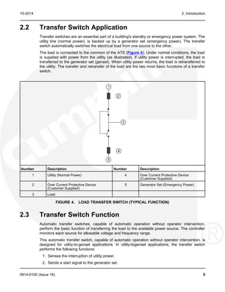
The document provides information about a GTEC automatic transfer switch, including:
1) Safety precautions when working with electrical equipment connected to the transfer switch.
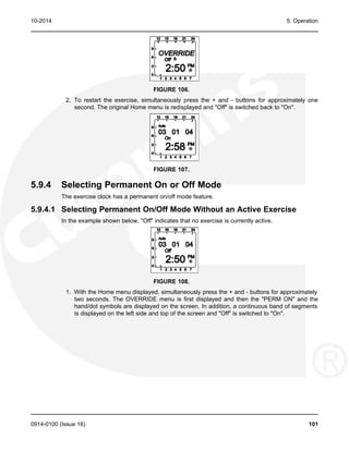
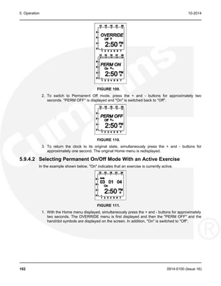
2) An overview of the transfer switch's functions in automatically transferring load between a utility power source and backup generator during outages.
3) Details on the transfer switch model identification numbers, components, controls, operation, installation and troubleshooting.


![Table of Contents 10-2014
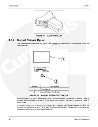
4.6.3 Elevator Relay Option................................................................................................ 29
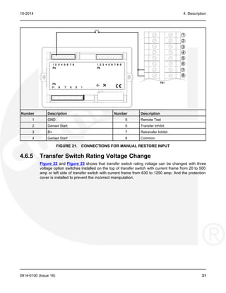
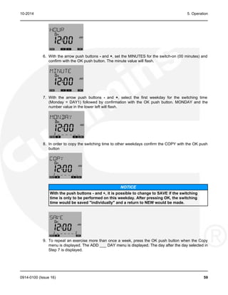
4.6.4 Manual Restore Option.............................................................................................. 30
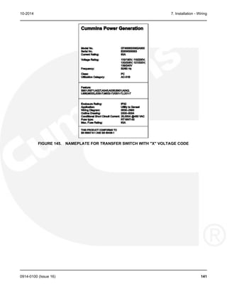
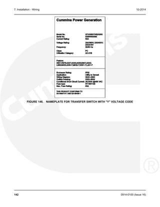
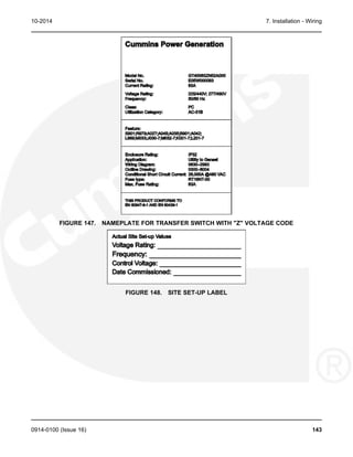
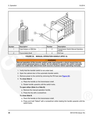
4.6.5 Transfer Switch Rating Voltage Change.................................................................... 31
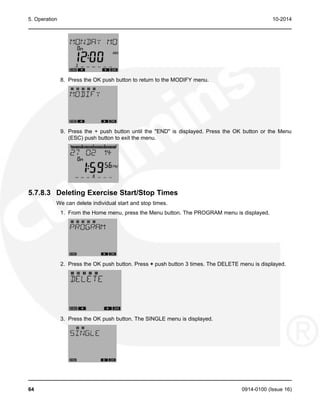
5. OPERATION ................................................................................................................................ 35
5.1 Time Delays.......................................................................................................................... 35
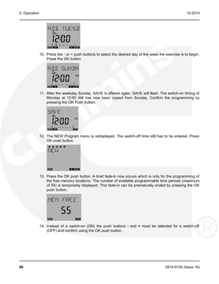
5.1.1 Time Delay Engine Start (TDES)............................................................................... 35
5.1.2 Time Delay Engine Cooldown (TDEC) ...................................................................... 35
5.1.3 Time Delay Normal-to-Emergency (TDNE) ............................................................... 35
5.1.4 Time Delay Emergency-to-Normal (TDEN) ............................................................... 36
5.1.5 Time Delay Programmed Transition (TDPT) ............................................................. 36
5.1.6 Time Delay Elevator (TDEL) Pre-Transfer................................................................. 36
5.1.7 Elevator Post Transfer Delay..................................................................................... 37
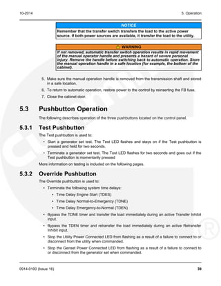
5.2 Manual Operation ................................................................................................................. 37
5.3 Pushbutton Operation........................................................................................................... 39
5.3.1 Test Pushbutton......................................................................................................... 39
5.3.2 Override Pushbutton .................................................................................................. 39
5.3.3 Set Exercise Pushbutton............................................................................................ 40
5.4 Test with or without Load...................................................................................................... 40
5.4.1 Test with Load Sequence of Events .......................................................................... 40
5.4.2 Test without Load Sequence of Events ..................................................................... 41
5.5 Sensors................................................................................................................................. 42
5.5.1 Utility Sensor.............................................................................................................. 42
5.5.2 Generator Sensor....................................................................................................... 43
5.5.3 Phase Check Sensor ................................................................................................. 43
5.5.4 Return to Programmed Transition.............................................................................. 44
5.6 Generator Set Exerciser ....................................................................................................... 44
5.6.1 General Information ................................................................................................... 44
5.6.2 Exercise with or without Load .................................................................................... 44
5.6.3 Integrated Exerciser................................................................................................... 44
5.6.4 Power Loss Backup ................................................................................................... 45
5.7 External Exercise Clock Option [TR 610 top2] ..................................................................... 46
5.7.1 Initial Start-Up ............................................................................................................ 47
5.7.2 LCD Lighting (Display Back Light) ............................................................................. 50
5.7.3 Using the Menu Buttons............................................................................................. 51
5.7.4 Using the -/+ Push Buttons........................................................................................ 51
5.7.5 Using the OK Push Button......................................................................................... 51
5.7.6 Setting the Time, Date with Summer/Winter Time (Daylight Savings Time) ............. 52
5.7.7 Setting Exercise Start and Stop Times...................................................................... 57
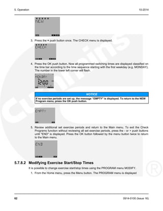
5.7.8 Checking the Programs ............................................................................................. 61
5.7.9 Initiating or Overriding an Exercise Program............................................................. 66
5.7.10 Selecting Permanent On/Off Mode.......................................................................... 67
5.7.11 Adding A Security Code........................................................................................... 69
5.7.12 After Programming the Exercise Clock.................................................................... 71
5.7.13 Resetting the Timer.................................................................................................. 72
5.8 Optional External Exerciser .................................................................................................. 72
ii 0914-0100 (Issue 16)](https://image.slidesharecdn.com/gtecownermanual-231001151059-2f3d1936/85/GTEC-OWNER-MANUAL-pdf-4-320.jpg)


![1. Safety Precautions 10-2014
• Remove all jewelry when working on electrical equipment.
• Wear safety glasses whenever servicing the transfer switch.
• Do not smoke near the batteries.
• Do not work on this equipment when mentally or physically fatigued, or after consuming
alcohol or any drug that makes the operation of equipment unsafe.
WARNING
Incorrect service or replacement of parts can result in death, severe personal injury,
and/or equipment damage. Service personnel must be qualified to perform electrical
and/or mechanical service.
1.3 Utility-To-Generator Set Applications
If the cabinet must be opened for any reason:
1. Move the operation selector switch on the generator set to STOP.
2. Disconnect the battery charger.
3. Disconnect the starting batteries of the generator set or sets (remove the ground [-] lead
first).
4. Remove AC power to the automatic transfer switch. If the instructions require otherwise,
use extreme caution due to the danger of shock hazard.
WARNING
AC power within the cabinet and the rear side of the cabinet door presents a shock
hazard that can cause severe personal injury or death. With the breaker in the OFF
position, the line side lugs are still energized.
2 0914-0100 (Issue 16)](https://image.slidesharecdn.com/gtecownermanual-231001151059-2f3d1936/85/GTEC-OWNER-MANUAL-pdf-8-320.jpg)


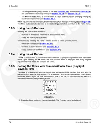
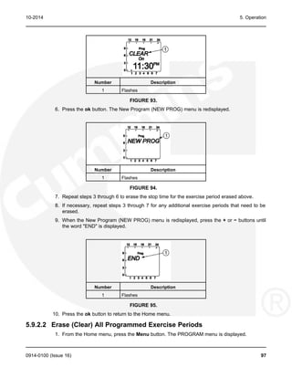
![5. Operation 10-2014
4. The Exercise LED stops flashing and remains on to signify that repeat exercise periods are
set (unless there are no repeat exercise periods). If there are no repeat exercise periods,
the Exercise LED goes out.
5.6.4.6 Exercise with Load Sequence of Events
1. When an exercise period becomes active, the Exerciser LED flashes at a rate of once per
second.
2. The control signals the generator set to start.
3. When the generator set output is acceptable, the control transfers the load to the generator
set, following the configuration set points.
4. After the exercise period has ended, the control retransfers the load back to the utility,
following the configured set points.
5. Once the load is connected to utility power, the control runs the generator set unload for
the duration of the cooldown timer (TDEC).
6. After the TDEC timer expires, the control signals the generator set to stop.
7. Unless the repeat exercise periods have been canceled, the Exercise LED quits flashing
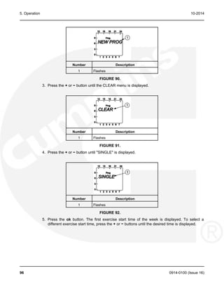
and remains on to signify that repeat exercise periods are set. If the exerciser is not set up
to repeat exercises, the Exercise LED goes out.
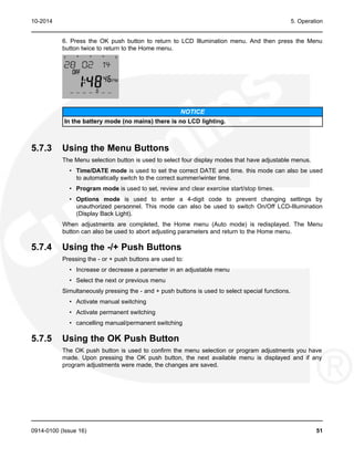
5.7 External Exercise Clock Option [TR 610 top2]
The optional external exercise clock includes a real-time clock that keeps track of the time and
date. The 7-DAY exercise clock can be set for automatic changeover for summer/winter
(daylight savings/standard) time. The exercise clock can be used with 120V AC, 230-240V AC
or 12-24 V AC or DC +10%/-15% operation.
Up to 56 programs are available to set exercise start and stop times. One program is required to
start an exercise period and a second one is required to stop an exercise period.
The exercise clock has a built-in test feature that can be used to initiate an exercise that has not
been programmed or cancel a programmed exercise in process.
NOTICE
The clock includes a non-replaceable lithium battery with a life expectancy of at least
ten years power reserved is reduced with memory card inserted (in battery mode). If the
clock battery is weak during a power failure, the clock will need to be replaced.
46 0914-0100 (Issue 16)](https://image.slidesharecdn.com/gtecownermanual-231001151059-2f3d1936/85/GTEC-OWNER-MANUAL-pdf-52-320.jpg)


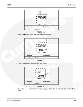
![5. Operation 10-2014
17. Press the OK push button to display the menu for setting the week when the summer
changeover will take place. Press the - or + push buttons until the desired week (1 to 5 [1 =
first week, 4 = fourth week, 5 = last week]) is displayed. The week value will flash.
18. Press the OK push button to display the menu for setting the day of the week when the
summer changeover will take place. Press the - or + push buttons until the desired week
day (1 to 7 [1 = Monday, 7 = Sunday]) is displayed. The word "DAY" and number in lower
left corner will flash.
TABLE 7. DAYS OF THE WEEK
Number Day of the Week
1 Monday
2 Tuesday
3 Wednesday
4 Thursday
5 Friday
6 Saturday
7 Sunday
19. Press the OK push button to display the menu for setting the hour of the day when the
summer changeover will take place. Press the - or + push buttons until the desired hour is
displayed. The hour value will flash.
NOTICE
The starting time can be set for 1.00 to 22.00 for 24h format and 1.00 to 12.00 for
12h format.
56 0914-0100 (Issue 16)](https://image.slidesharecdn.com/gtecownermanual-231001151059-2f3d1936/85/GTEC-OWNER-MANUAL-pdf-62-320.jpg)
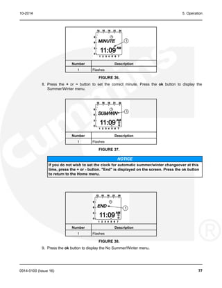
![10-2014 5. Operation
20. Press the Ok push button to display the menu for setting the month when the winter
changeover will take place. Press the - or + push buttons until the desired month is
displayed. Month value will flash.
21. Press the OK push button to display the menu for setting the week when the winter
changeover will take place. Press the - or + push buttons until the desired week ( 1 to 5 [1
= first week, 4 = fourth week, 5 = last week]) is displayed.
TABLE 8. WEEK TABLE
Number Week
1 First Week
2 Second Week
3 Third Week
4 Fourth Week
5 Last Week
NOTICE
The starting time of the winter changeover is the same time that was set
previously.
22. Press the OK push button followed by the Menu button twice. The Home menu is
displayed.
5.7.7 Setting Exercise Start and Stop Times
Up to 56 programs can be used to set exercise start and stop times. One program is required to
start an exercise period and a second one is required to stop an exercise period.
0914-0100 (Issue 16) 57](https://image.slidesharecdn.com/gtecownermanual-231001151059-2f3d1936/85/GTEC-OWNER-MANUAL-pdf-63-320.jpg)


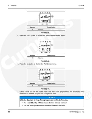
![5. Operation 10-2014
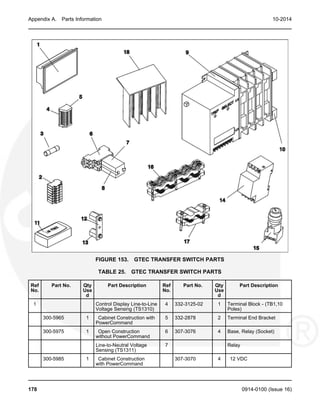
Number Description
1 Flashes
FIGURE 33.
5. Press the + or − button to set the correct month. Press the ok button to display the Day
menu.
Number Description
1 Flashes
FIGURE 34.
6. Press the + or - button to set the correct day. Press the ok button to display the Hour
menu. A small triangle is displayed above the assigned number in the display for the day of
the week (1 = Monday, 7 = Sunday).
Number Description
1 Triangle
2 Flashes
FIGURE 35.
7. Press the + or - button to set the correct hour. A line is displayed on the screen indicating
the hour of the day selected (the left side of the screen is for the first half of the day [AM]
and the top of the screen is for the second half of the day [PM]). Press the ok button to
display the Minute menu.
76 0914-0100 (Issue 16)](https://image.slidesharecdn.com/gtecownermanual-231001151059-2f3d1936/85/GTEC-OWNER-MANUAL-pdf-82-320.jpg)

![5. Operation 10-2014
15. Press the ok button to display the menu for setting the week when the Summer
changeover will take place. Press the + or − buttons until the desired week (1 thru 5 [1 =
first week, 4 = fourth week, 5 = last week]) is displayed.
Number Description
1 Flashes
FIGURE 45.
16. Press the ok button to display the menu for setting the hour of the day when the Summer
changeover will take place. Press the + or − buttons until the desired hour (1 through 3) is
displayed.
Number Description
1 Flashes
FIGURE 46.
NOTICE
The starting time can only be set for 1:00 (1.00), 2:00 (2.00), or 3:00 (3.00) AM.
17. Press the ok button to display the menu for setting the month when the Winter changeover
will take place. Press the + or − buttons until the desired month is displayed.
80 0914-0100 (Issue 16)](https://image.slidesharecdn.com/gtecownermanual-231001151059-2f3d1936/85/GTEC-OWNER-MANUAL-pdf-86-320.jpg)
![10-2014 5. Operation
Number Description
1 Flashes
FIGURE 47.
18. Press the ok button to display the menu for setting the week when the Winter changeover
will take place. Press the + or − buttons until the desired week (1 through 5 [1 = first week,
4 = fourth week, 5 = last week]) is displayed.
Number Description
1 Flashes
FIGURE 48.
NOTICE
The starting time for the winter changeover is the same as set in step 16.
19. Press the ok button. The Home menu is redisplayed and the appropriate summer/winter
symbol is displayed.
Number Description
1 Flashes
FIGURE 49.
0914-0100 (Issue 16) 81](https://image.slidesharecdn.com/gtecownermanual-231001151059-2f3d1936/85/GTEC-OWNER-MANUAL-pdf-87-320.jpg)
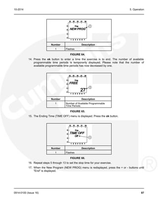
![10-2014 5. Operation
Number Description
1 Flashes
FIGURE 52.
3. Press the ok button. The number of available programmable time periods (maximum of 28)
is temporarily displayed.
Number Description
1 Flashes
FIGURE 53.
4. The Starting Time (TIME ON) menu is displayed. Press the ok button.
Number Description
1 Flashes
FIGURE 54.
5. The Hour menu is displayed. Press the + or - buttons to set the desired exercise starting
hour (default = 12:00 AM). A line is displayed on the screen indicating the hour of the day
selected (the left side of the screen is for the first half of the day [AM] and the top of the
screen is for the second half of the day [PM]). Press the ok button.
0914-0100 (Issue 16) 83](https://image.slidesharecdn.com/gtecownermanual-231001151059-2f3d1936/85/GTEC-OWNER-MANUAL-pdf-89-320.jpg)


![5. Operation 10-2014
FIGURE 126.
8. Press the + or − button until the correct minute is displayed. Press the ok button. The
screen then displays the correct date and time.
FIGURE 127.
5.10 Planned Maintenance
Performing the annual planned maintenance procedures increases reliability of the transfer
switch.
The following procedures must be done only by trained and experienced personnel, according
to procedures in Chapter 8. If repair or component replacement is necessary, call your dealer or
distributor.
WARNING
AC power within the cabinet and the rear side of the cabinet door presents a shock
hazard that can cause severe personal injury or death. Incorrect installation, service, or
parts replacement can result in severe personal injury, death, and/or equipment
damage. All corrective service procedures must be done only by technically qualified
personnel, according to procedures in Chapter 9.
WARNING
The transfer switch presents a shock hazard that can cause severe personal injury or
death unless all AC power is removed. Be sure to set the genset operation selector
switch to Stop, disconnect AC line power, disconnect the battery charger from its AC
power source, and disconnect the starting battery (negative [-] lead first) before
servicing.
WARNING
Ignition of explosive battery gases can cause severe personal injury. Do not smoke or
cause any spark, arc, or flame while servicing batteries.
108 0914-0100 (Issue 16)](https://image.slidesharecdn.com/gtecownermanual-231001151059-2f3d1936/85/GTEC-OWNER-MANUAL-pdf-114-320.jpg)
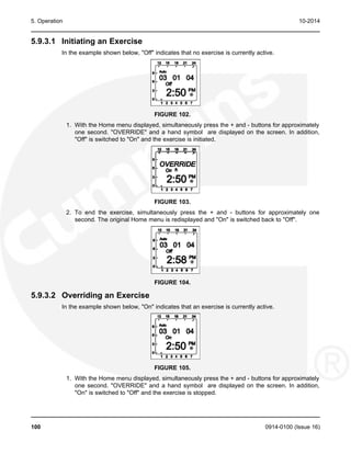
![10-2014 5. Operation
WARNING
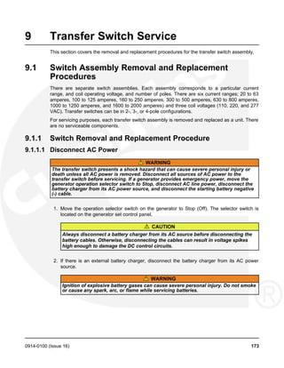
1. Disconnect All Sources of AC Power:
a. Disconnect both AC power sources from the transfer switch before continuing. Turn
the generator set operation selector switch to Stop. (The selector switch is located on
the generator set control panel.)
b. If there is an external battery charger, disconnect it from its AC power source.
c. Disconnect the set starting battery (negative [-] lead first).
2. Clean
a. Thoroughly dust and vacuum all controls, meters, switching mechanism components,
interior buswork, and connecting lugs.
b. Close the cabinet door and wash exterior surfaces with a damp sponge (mild
detergent and water). Do not allow water to enter the cabinet, especially at
meters, lamps, and switches.
3. Inspect
a. Check buswork and supporting hardware for carbon tracking, cracks, corrosion, or any
other types of deterioration. If replacement is necessary, call your dealer or distributor.
b. Check stationary and movable contacts. If contact replacement is necessary, the
procedures are described in the Chapter 7.
c. Check system hardware for loose connections. Tighten as indicated in step 4
(Perform Routine Maintenance).
d. Check all control wiring and power cables (especially wiring between or near hinged
door) for signs of wear or deterioration.
e. Check all control wiring and power cables for loose connections. Tighten as indicated
in step 4 (Perform Routine Maintenance).
f. Check the cabinet interior for loose hardware. Tighten as indicated in step 4 (Perform
Routine Maintenance).
4. Perform Routine Maintenance
a. Tighten buswork, control wiring, power cables, and system hardware, as necessary.
Hardware torque values are given in Chapter 9. Retorque all cable lug connections.
Lug torque requirements are listed in Chapter 7.
5. Connect AC Power and Check Operation
a. Connect the set starting battery (negative [-] lead last). Connect the utility AC power
source, enable the genset power source. If applicable, connect power to the battery
charger.
b. Verify proper operation of the battery charger.
c. Test system operation as described in this section. Close and lock the cabinet door.
5.11 Control Panel Configuration
The control panel can be used to configure ATS functions. When in Configuration Mode, the
value code for the various control functions can be modified.
0914-0100 (Issue 16) 109](https://image.slidesharecdn.com/gtecownermanual-231001151059-2f3d1936/85/GTEC-OWNER-MANUAL-pdf-115-320.jpg)


![10-2014 7. Installation - Wiring
• Use Column D for connections to TB1-1 (GND) and TB1-3 (B+) if a 10 Amp battery
charger is installed in the transfer switch.
TABLE 13. WIRE SPECIFICATIONS
Wire Size (AWG) Distance in Meters, One Way
[mm2
] (Multiply by 3.3 for Feet)
Column A Column B Column C Column D
16 [1.5] 305 130 38 8
14 [2.5] 488 206 61 12
12 [4.0] 732 329 91 18
10 [6.0] 1219 523 152 31
Wire resistance must not exceed 0.5 ohm per line. Use stranded wire only. For connection to
the screw terminal, strip the insulation back 3/8 inch (10 mm).
Remote starting (for Cummins Power Generation water-cooled generator sets only) uses
terminals B+, GND (ground), and RMT of terminal block TB1, Figure 138. Connect these
terminals to like terminals on the generator set. Refer to Interconnect Wiring diagram shipped
with the switch.
• For PCC 3100 and PCC 2100 generator set controls, install a jumper between TB1-1 and
TB1-2 for ground-to-start connection.
• For PCC 1301, 1302, 2300, and 3300 generator set controls, install a jumper between
TB1-10 and TB1-11 for ground-to-start connection.
• For Detector 12 generator set controls, install a jumper between TB1-2 and TB1-3 for B+
start.
• For PCC 3200 generator set controls requiring a dry contact start, do not install a jumper.
Be sure to check the Interconnect Wiring diagram shipped with the transfer switch.
7.1.1.2 Auxiliary Contacts
Auxiliary contacts, for external alarm or control circuitry, are available for the Normal (utility
power) and Emergency (generator set power) sides of the transfer switch. Connections for the
auxiliary contacts can be made on terminal block TB1, Figure 139. The contacts have ratings of
5 amperes at 250 VAC. Figure 139 shows the normally open and normally closed positions of
the auxiliary contacts with the transfer switch in the neutral position. Moving the transfer switch
to Normal or Emergency actuates the corresponding auxiliary contacts.
Use number 22 (0.4 mm2
) to number 12 AWG (4 mm2
) wire. For connection to the screw
terminal, strip the insulation back 3/8 inch (10 mm).
0914-0100 (Issue 16) 133](https://image.slidesharecdn.com/gtecownermanual-231001151059-2f3d1936/85/GTEC-OWNER-MANUAL-pdf-139-320.jpg)