Download as PDF, PPTX


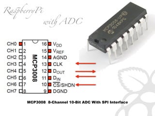
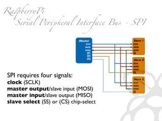

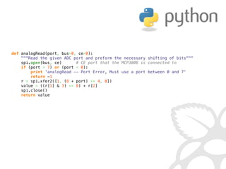


![IN =[0000 0001][1CNL ----][---- ----]
(8+channel) 4
OUT=[---- ----][---- -XXX][XXXX XXXX] (10bit)
((r[1] 3) 8) + r[2]](https://image.slidesharecdn.com/gettingstarted-ucsd2013-130727155123-phpapp02/85/Getting-Started-With-Raspberry-Pi-UCSD-2013-61-320.jpg)
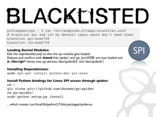
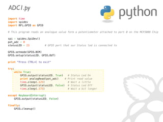
![IN =[0000 0001][1CNL ----][---- ----]
(8+channel) 4
OUT=[---- ----][---- -XXX][XXXX XXXX]
r[0] ((r[1] 3) 8) + r[2]
r = spi.xfer2( [1, (8+chnnl)4, 0] )
return ((r[1] 3) 8) + r[2]](https://image.slidesharecdn.com/gettingstarted-ucsd2013-130727155123-phpapp02/85/Getting-Started-With-Raspberry-Pi-UCSD-2013-62-320.jpg)
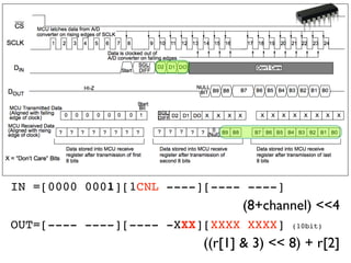
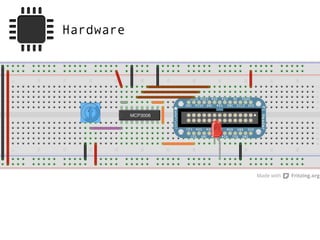
![def analogRead(port, bus=0, ce=0):
Read the given ADC port and preform the necessary shifting of bits
spi.open(bus, ce) # CE port that the MCP3008 is connected to
if (port 7) or (port 0):
print 'analogRead -- Port Error, Must use a port between 0 and 7'
return -1
r = spi.xfer2([1, (8 + port) 4, 0])
value = ((r[1] 3) 8) + r[2]
spi.close()
return value](https://image.slidesharecdn.com/gettingstarted-ucsd2013-130727155123-phpapp02/85/Getting-Started-With-Raspberry-Pi-UCSD-2013-63-320.jpg)


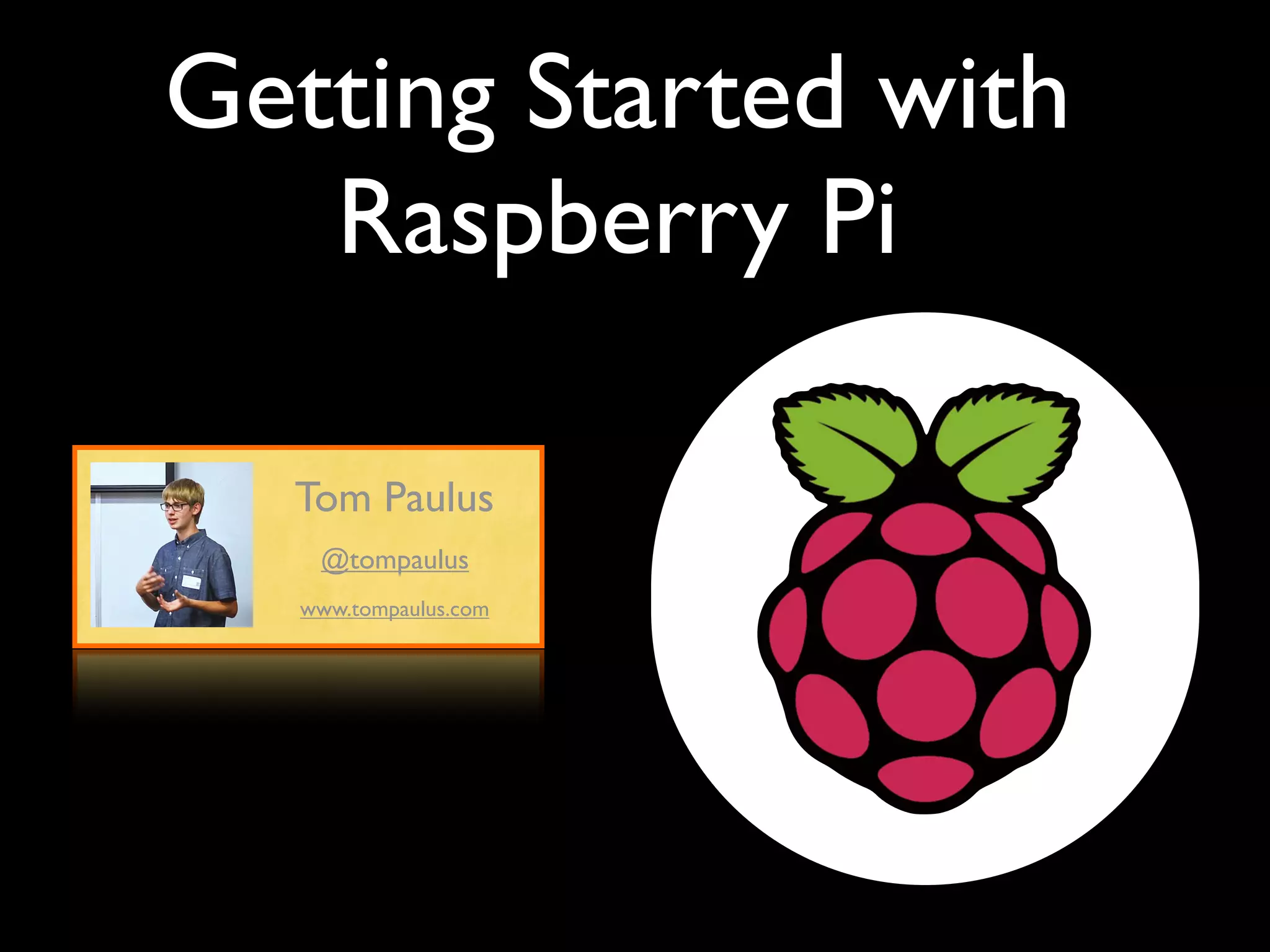
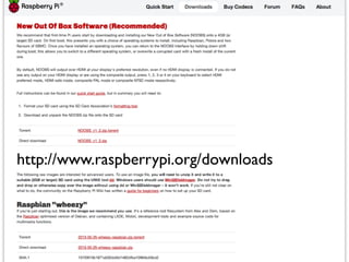
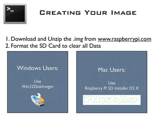
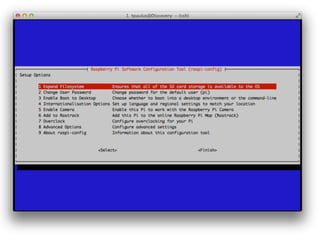
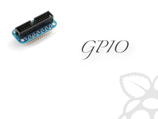
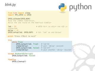
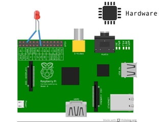
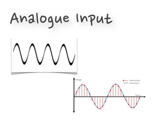
The document provides information to help get started with the Raspberry Pi. It recommends downloading the operating system image from the Raspberry Pi website. It then discusses setting up the SD card with the image for both Windows and Mac users. The document proceeds to provide examples of code to blink an LED using the GPIO pins and read analog sensor values using the SPI interface. It demonstrates connecting additional hardware like displays and buttons. The examples show how to smooth sensor readings and control the display. The document emphasizes cleaning up resources to avoid issues.


![[5]投影片 futurewad樹莓派研習會 141218](https://cdn.slidesharecdn.com/ss_thumbnails/5futurewad141218-141219162301-conversion-gate02-thumbnail.jpg?width=640&height=640&fit=bounds)