Downloaded 174 times
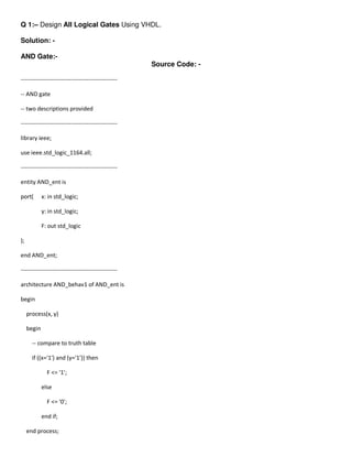
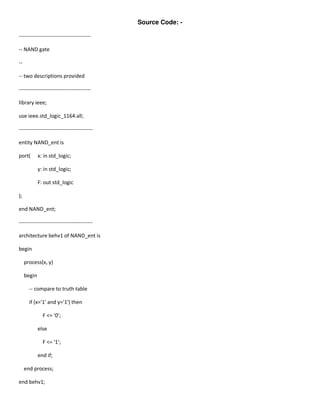
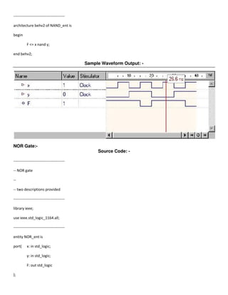
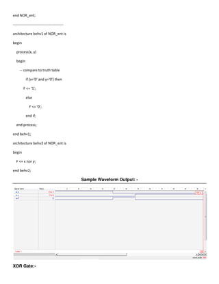
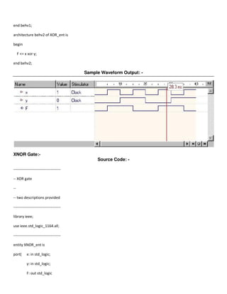
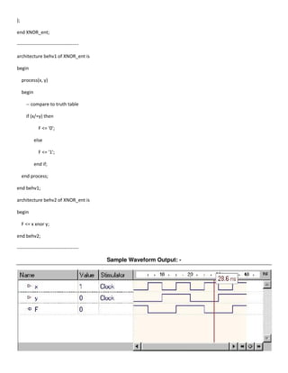
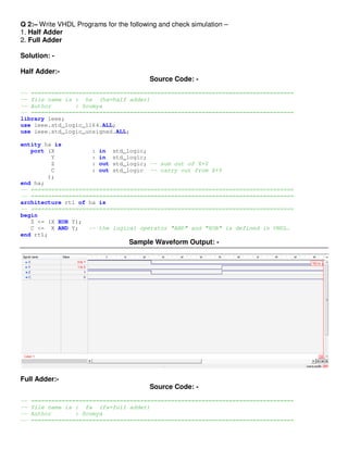
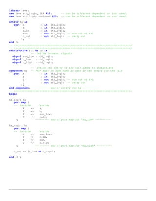
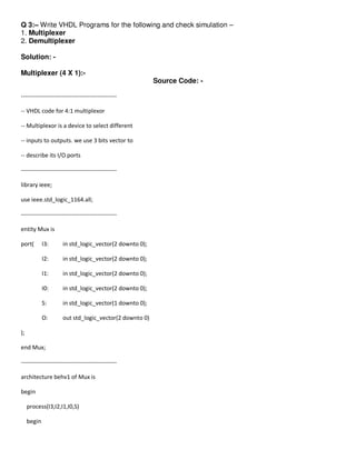
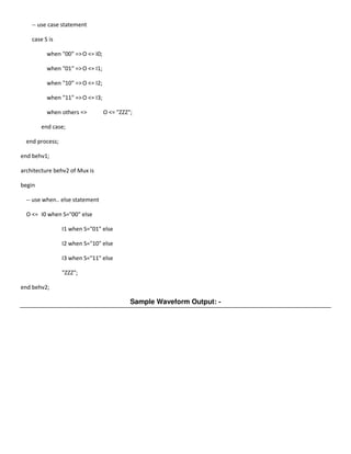
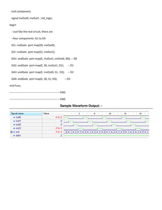
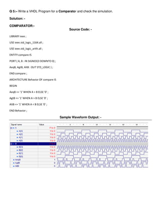
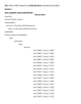
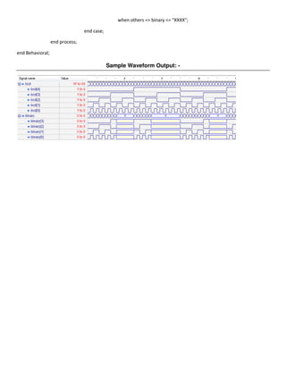
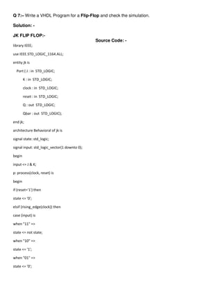
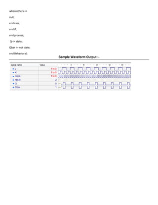
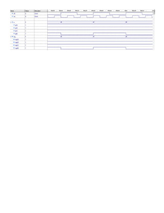
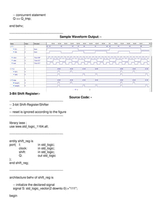
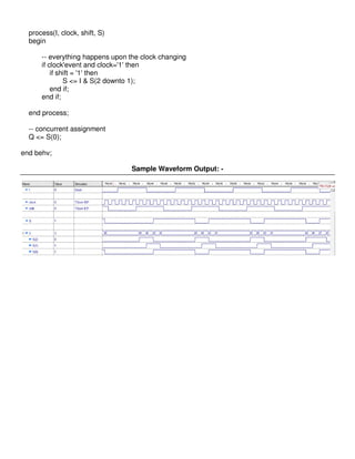

This document provides VHDL code for implementing various logic gates and basic digital circuits. It includes code for AND, OR, NOT, NAND, NOR, XOR and XNOR gates. It also provides code for half adder, full adder, multiplexer, demultiplexer, decoder, encoder, comparator, BCD to binary converter, JK flip-flop, and an n-bit counter. For each circuit, the VHDL code and a sample waveform output is given. The purpose is to design these basic digital components using VHDL and simulate their behavior.