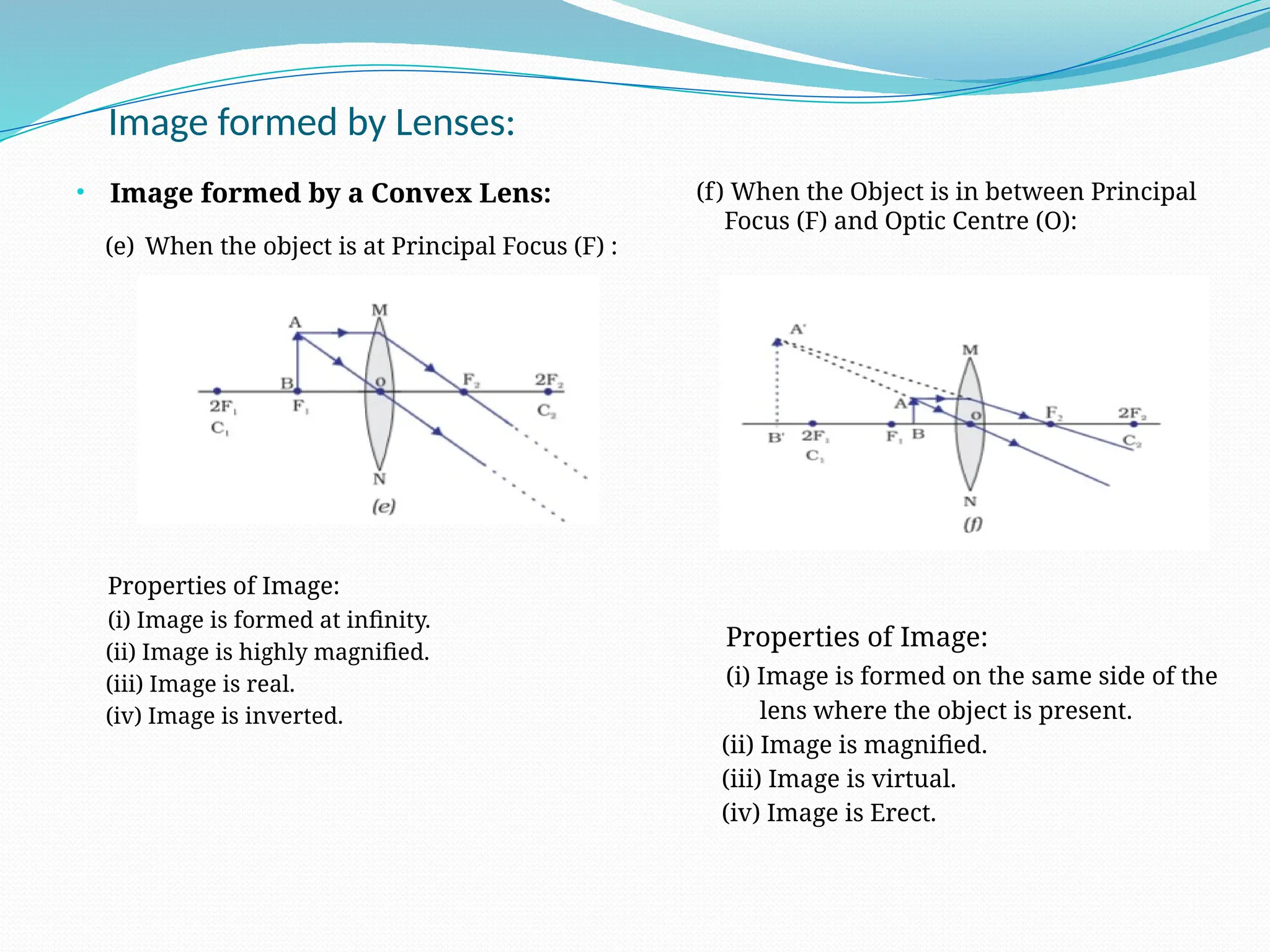
Chapter- 15
Light, Mirrors
and
Lenses
Period-1
Light, Mirrors and Lenses:
• Rays:
Single lines of light is known as
Rays.
• Beam:
A collection of rays of light is
known as Beam.
• Rectilinear Propagation of Light:
The phenomenon by virtue of
which light travels along a straight
path is known as Rectilinear
Propagation of Light.
• Reflection of Light:
The phenomenon in which the
incident light is sent back to the
same medium where from it came
by a reflecting surface is known as
Reflection of Light.
Light, Mirrors and Lenses:
• Regular Reflection:
The type of reflection in which
when parallel rays of light fall on a
smooth, even surface, the reflected
rays are also parallel to each other
is known as Regular Reflection.
e.g. Polished Metal surfaces,
Mirrors etc.
• Irregular or Diffuse Reflection:
The type of reflection in which
when parallel rays of light fall on
an uneven surface, the reflected
rays get scattered in all directions
is known as Irregular Reflection.
e.g. Soil surface, Rough floor etc.
.
Light, Mirrors and Lenses:
• Real Image:
The image which is formed by the
actual intersection of the reflected or
refracted rays of light is known as Real
Image.
Real images can be obtained on a
screen.
e.g. Image formed by a Concave Mirror,
Image formed by a Convex lens.
• Virtual Image:
The image which is formed by the
intersection of the extended reflected
or refracted rays of light is known as
Virtual Image.
Virtual images can not be obtained on
a screen.
e.g. Image formed by a Convex Mirror,
Image formed by a Concave lens.
.
Self Assessment-1
1. What is a Ray of Light?
2. What is a Beam of Light?
3. What is Rectilinear Propagation of Light?
4. What is Reflection of Light?
5. What is Regular Reflection of Light?
6. What is Irregular or Diffuse Refection of Light?
7. Differentiate between Regular and Irregular Reflection of Light.
8. What is a Real Image?
9. What is a Virtual Image?
10. Differentiate between a Real Image and a Virtual Image.
Period-2
Light, Mirrors and Lenses:
• Mirrors:
A mirror is a smooth, polished
surface that can reflect a clear
image. It is made of a reflecting
material such as glass. Mirrors
can have plane (flat) or curved
reflecting surfaces.
• Plane Mirror:
Plane mirrors have flat
reflecting surfaces.
Light, Mirrors and Lenses:
• Image formed by a Plane Mirror
 Properties:
• Image formed by a plane mirror is always
virtual and erect.
• The size of the image is equal to that of the
object.
• The image formed is as far behind the mirror
as the object is in front of it.
• The image formed by a plane mirror is
laterally Inverted.
 Lateral Inversion:
The phenomenon in which
left side of the object
appears as the right side of
the image and vice-versa
on reflection in a plane
mirror is called Lateral
Inversion.
Self Assessment-2
1. What are Mirrors?
2. What is a Plane Mirror?
3. State the Laws of Reflection.
4. What is Lateral Inversion?
5. Write the English Alphabets in the Laterally Inverted form.
6. Draw a neat labeled diagram to show the image formed by a Plane Mirror.
7. Mention the properties of the image formed by a Plane Mirror.
8. What are Spherical Mirrors?
9. What is a Concave Mirror?
10. What is a convex Mirror?
11. Define the following terms related to a Spherical Mirror.
(a) Pole (b) Centre of Curvature (c) Radius of Curvature (d) Principal Axis (e) Principal Focus (f) Object Distance
(g) Image Distance (h) Focal Length (i) Aperture
Period-3
Image formed by Spherical Mirrors:
• Types of rays used to draw
a ray diagram:
(a) Incident rays parallel to
Principal Axis after reflection
passes or appear to pass through
Principal Focus (F).
(b) An Incident ray passing
through
the Principal Focus (F) after
reflection passes parallel to the
Principal Axis.
Image formed by Spherical Mirrors:
• Types of rays used to draw
a ray diagram:
(c) An Incident ray passing
through or appear to pass
through the Centre of Curvature
(C) (Normal Incidence), is
reflected back.
(d) An Incoming ray incident at
pole (P) making an Angle of
Incidence ( i) with the
∠
Principal Axis is reflected at an
Angle of Reflection ( r) such
∠
that i= r.
∠ ∠
Image formed by Spherical Mirrors:
• Image formed by a Concave Mirror:
(a) When the object is at Infinity:
Properties of Image:
(i) Image is formed at Principal Focus
(F).
(ii) Image is point size.
(iii) Image is real.
(b) When the Object is beyond Centre of
Curvature (C):
Properties of Image:
(i) Image is formed in between Centre of
Curvature (C) and Principal Focus (F).
(ii) Image is diminished.
(iii) Image is real.
(iv) Image is inverted.
Image formed by Spherical Mirrors:
• Image formed by a Concave Mirror:
(c) When the object is at Center of
Curvature (C) :
Properties of Image:
(i) Image is formed at Centre of Curvature (C).
(ii) Image is of same size of the object.
(iii) Image is real.
(iv) Image is inverted.
(d) When the Object is in between Centre of
Curvature (C) and Principal Focus (F):
Properties of Image:
(i) Image is formed in beyond Centre of
Curvature (C).
(ii) Image is magnified.
(iii) Image is real.
(iv) Image is inverted.
Image formed by Spherical Mirrors:
• Image formed by a Concave Mirror:
(e) When the object is at Principal Focus (F) :
Properties of Image:
(i) Image is formed at infinity.
(ii) Image is highly magnified.
(iii) Image is real.
(iv) Image is inverted.
(f) When the Object is in between Principal
Focus (F) and Pole (P):
Properties of Image:
(i) Image is formed in behind the mirror.
(ii) Image is magnified.
(iii) Image is virtual.
(iv) Image is Erect.
Image formed by Spherical Mirrors:
• Image formed by a Convex Mirror:
(a) When the object is at Infinity:
Properties of Image:
(i) Image is formed behind the mirror.
(ii) Image is point size.
(iii) Image is virtual.
(iv) Image is erect.
(b) When the object is closer to the
Convex Mirror:
Properties of Image:
(i) Image is formed behind the mirror.
(ii) Image is diminished.
(iii) Image is virtual.
(iv) Image is erect.
Self Assessment-3
1. Draw the four different types of incident rays that are used to draw the ray diagram to show the image formed by a
Spherical Mirror.
2. Draw the ray diagram to show the image formed by a Concave Mirror when the object is at Infinity.
3. Draw the ray diagram to show the image formed by a Concave Mirror when the object is beyond Centre of Curvature (C).
4. Draw the ray diagram to show the image formed by a Concave Mirror when the object is at Centre of Curvature (C).
5. Draw the ray diagram to show the image formed by a Concave Mirror when the object is between Centre of Curvature (C)
and Principal Focus (F).
6. Draw the ray diagram to show the image formed by a Concave Mirror when the object is at Principal Focus (F).
7. Draw the ray diagram to show the image formed by a Concave Mirror when the object is between Principal Focus (F) and
Pole (P).
8. Draw the ray diagram to show the image formed by a Convex Mirror when the object is at Infinity.
9. Draw the ray diagram to show the image formed by a Convex Mirror when the object is closer to the Mirror.
Period-4
Uses of Spherical Mirrors:
 Uses of Concave Mirror
(a) Shaving Mirrors
(b) Head mirrors
(c) Astronomical Telescope
(d) Headlights
Uses of Spherical Mirrors:
 Uses of Concave Mirror
(e) Torch Lights
(f) Solar Furnaces
(g) Ophthalmoscope (for
checking
of retina).
Uses of Spherical Mirrors:
 Uses of Convex Mirror
(a) Rear view mirror of
automobiles
(b) Traffic mirrors
Refraction
 When light travels obliquely
from one transparent medium
into another, it bends at the
Interface. This bending of
light is called Refraction of
light.
 When light travels from a
rarer medium to a denser
medium, it bends towards the
normal.
 When light travels from a
denser medium to a rarer
medium, it bends away from
the normal.
Spherical Lenses:
 A spherical lens is a transparent material
bounded by two surfaces, one or both of
which are spherical.
 Spherical lenses are of two main types.
They are convex and concave lenses.
 (i) Convex lens : A Convex lens is thicker in
the middle and thinner at the edges.
Rays of light parallel to the principal axis
after refraction through a convex lens meet
at a point (converge) on the principal axis.
 (ii) Concave lens : A Concave lens is thinner
in the middle and thicker at the edges.
Rays of light parallel to the principal axis
after refraction get diverged and appear to
come from a point on the principal axis on
the same side of the lens.
Convergent and Divergent lenses:
 Convergent Lens:
 If the distance of separation
amongst the incident parallel
rays of light decreases after
refraction through a lens,
then the lens is called a
Convergent lens. e.g. Convex
lens
 Divergent Lens:
 If the distance of separation
amongst the incident parallel
rays of light increases after
refraction through a lens,
then the lens is called a
Divergent lens. e.g. Concave
lens
Refractive Index
 Let v1 be the speed of light in medium 1 and v2 be
the speed of light in medium 2.
The refractive index of medium 2 with respect to
medium 1 is given by the ratio of the speed of
light in medium 1 and the speed of light in
medium 2. This is usually represented by the
symbol n21 , which can be expressed in an
equation form as
Speed of light in medium 1 v1
n21 = =
Speed of light in medium 2 v2
 By the same argument, the refractive index of
medium 1 with respect to medium 2 is
represented as n12. It is can be expressed in an
equation form as
Speed of light in medium 2 v2
n12 = =
Speed of light in medium 1 v1
Some Technical Terms related to Lenses
 Optic Centre (O):
The geometrical Centre of the lens is called its Optic
Centre.
A ray of light passing through the Optic Centre goes
undeviated.
 Centers of Curvatures (C1 & C2):
Centre of Curvature of a surface of a lens is defined
as the centre of that sphere of which that surface
forms a part.
There are two centers of curvature of a lens, one
each belonging to both the surfaces. ( OC1 = R1, OC2 =
R2)
 Principal Axis (C1OC2):
A line joining the two centers of curvature and
passing through the optical centre is called Principal
Axis.
 Radius of Curvature (R1 & R2):
Radius of curvature of a surface of a lens is defined
as the radius of that sphere of which the surface
forms a part.
There are two radii of curvature of a lens, one each
belonging to both the surfaces.
Some Technical Terms related to Lenses
 Principal Focus (F):
Principal focus of a lens is a point on the principal
axis, at which a beam of light coming parallel to
principal axis actually meets or appears to meet
after refraction through the lens.
 Focal Length ( f1 & f2):
Focal Length of a lens is defined as the distance
between principal focus and its optical centre.
A lens can be used from both sides. So, there are
two focal lengths for a lens, one each belonging to
both the surfaces. (OF1 = f1, OF2 = f2)
 Object Distance(u):
The distance of separation between the optic
centre and the object, measured along the
principal axis is called the Object Distance.
 Image Distance(v):
The distance of separation between the optic
centre and the image, measured along the
principal axis is called the Image Distance.
Self Assessment-4
1. Mention four uses of Concave Mirrors.
2. Mention two uses of Convex mirror.
3. What is Refraction?
4. What happens to the refracted ray of light, if refraction is taking place from a rarer medium to a denser medium?
5. What happens to the refracted ray of light, if refraction is taking place from a denser medium to a rarer medium?
6. What is a Convex Lens?
7. What is a Concave Lens?
8. What is Optic Centre?
9. Define Principal Focus (F) of a lens.
10. What is Object Distance (u)?
11. What is Image distance (v)?
12. How many Focal Lengths does a Convex Lens have and why?
13. Define Focal length (f) of a Lens.
14. What is a Convergent Lens?
15. What is a Divergent Lens?
Period-5
Real Image & Virtual Image
 Real Image:
The image formed by the actual
intersection of reflected rays or refracted
rays is known as Real Image.
Real images can be obtained on a screen.
 Virtual Image:
The image formed by the intersection of
extended reflected rays or extended
refracted rays is known as Virtual Image.
Virtual images cannot be obtained on a
screen.
Magnified & Diminished Image
Inverted & Erect Image
 Magnified and Diminished
Image:
 Magnified Image:
If the size of the image is bigger than the size of
the object then the image is called a Magnified
Image.
 Diminished Image:
If the size of the image is smaller than the size of
the object then the image is called a Diminished
Image.
 Inverted and Erect Image:

Inverted Image:
The image which is up side down as compared
to the object is known as Inverted Image.

Erect Image:
The image in which the directions are the
same as those in the object is known as Erect
Image.
Image formed by Lenses:
• Types of rays used to draw
a ray diagram:
(a) Incident rays parallel to
Principal Axis after refraction
passes or appear to pass through
Principal Focus (F).
(b) An Incident ray passing
through
the Principal Focus (F) after
refraction passes parallel to the
Principal Axis.
Image formed by Spherical Mirrors:
• Types of rays used to draw
a ray diagram:
(c) An Incident ray passing
through
the Optic Center (O)
(Normal Incidence), is
refracted
without any deviation.
Image formed by Lenses:
• Image formed by a Convex lens:
(a) When the object is at Infinity:
Properties of Image:
(i) Image is formed at Principal Focus
(F).
(ii) Image is point size.
(iii) Image is real.
(b) When the Object is beyond Centre of
Curvature (C):
Properties of Image:
(i) Image is formed in between Centre of
Curvature (C) and Principal Focus (F).
(ii) Image is diminished.
(iii) Image is real.
(iv) Image is inverted.
Image formed by Lenses:
• Image formed by a Convex Lens:
(c) When the object is at Center of
Curvature (C) :
Properties of Image:
(i) Image is formed at Centre of Curvature (C).
(ii) Image is of same size of the object.
(iii) Image is real.
(iv) Image is inverted.
(d) When the Object is in between Centre of
Curvature (C) and Principal Focus (F):
Properties of Image:
(i) Image is formed in beyond Centre of
Curvature (C).
(ii) Image is magnified.
(iii) Image is real.
(iv) Image is inverted.
Image formed by Lenses:
• Image formed by a Convex Lens:
(e) When the object is at Principal Focus (F) :
Properties of Image:
(i) Image is formed at infinity.
(ii) Image is highly magnified.
(iii) Image is real.
(iv) Image is inverted.
(f) When the Object is in between Principal
Focus (F) and Optic Centre (O):
Properties of Image:
(i) Image is formed on the same side of the
lens where the object is present.
(ii) Image is magnified.
(iii) Image is virtual.
(iv) Image is Erect.
Image formed by Lenses:
• Image formed by a Concave Lens:
(a) When the object is at Infinity:
Properties of Image:
(i) Image is formed on the same side of the
lens where the object is present.
(ii) Image is point size.
(iii) Image is virtual.
(iv) Image is erect.
(b) When the object is in between Centre
of Curvature (C) and Principal Focus
(F)
Properties of Image:
(i) Image is formed on the same side
of the lens where the object is
present.
(ii) Image is diminished.
(iii) Image is virtual.
(iv) Image is erect.
Self Assessment-5
1. Draw the three different types of incident rays that are used to draw the ray diagram to show the image formed by a
Lens.
2. Draw the ray diagram to show the image formed by a Convex Lens when the object is at Infinity.
3. Draw the ray diagram to show the image formed by a Convex Lens when the object is beyond Centre of Curvature (C).
4. Draw the ray diagram to show the image formed by a Convex Lens when the object is at Centre of Curvature (C).
5. Draw the ray diagram to show the image formed by a Convex Lens when the object is between Centre of Curvature (C)
and Principal Focus (F).
6. Draw the ray diagram to show the image formed by a Convex Lens when the object is at Principal Focus (F).
7. Draw the ray diagram to show the image formed by a Convex Lens when the object is between Principal Focus (F) and
Optic Center (O).
8. Draw the ray diagram to show the image formed by a Concave Lens when the object is at Infinity.
9. Draw the ray diagram to show the image formed by a Concave Lens when the object is between Centre of Curvature (C)
and Principal Focus (F).
Period- 6
Uses of Lenses:
 Uses of Convex Lens
(a) Magnifying Glass
(b) Eye Glasses
(c) Cameras
(d) Microscopes
Uses of Lenses:
 Uses of Concave Lens
(a) Telescope and Binoculars
(b) Eye Glasses
(c) Cameras
(d) Lasers
(e) Flashlights
(f) Peepholes
White Light and the colours of the Spectrum:
 White Light:
• White Light consists of seven
colours.
 V-Violet
 I- Indigo
 B- Blue
 G-Green
 Y-Yellow
 O-Orange
 R-Red
 Spectrum:
• The band of constituent colours
of white light is called spectrum.
Dispersion of White Light in Nature
Rainbow:
 A rainbow is a natural spectrum appearing in the sky
after a rain shower .
 It is caused by dispersion of sunlight by tiny water
droplets, present in the atmosphere.
 A rainbow is always formed in a direction opposite
to that of the Sun.
 The water droplets act like small prisms. They refract
and disperse the incident sunlight, then reflect it
internally, and finally refract it again when it comes
out of the raindrop.
 Due to the dispersion of light and internal reflection,
different colours reach the observer’s eye.
 Critical Angle:
The angle of incidence corresponding to which the
value of angle of refraction is 90 ⁰ ,when light refracts
from denser medium to rarer medium is known as
Critical Angle.
 Total Internal Reflection:
When light ray moves from a denser medium to a
rarer medium and the value of the angle of incidence
is more than the critical angle, then the refracted ray
comes back to the denser medium. This phenomenon
is known as Total Internal Reflection.
Refraction through a Prism
 Prism: A Prism is a transparent optical object
with flat, polished surfaces that refract light. At
least two of the polished surfaces must have an
angle between them.
 Bending of light: Light changes its speed when
it moves from one medium to another medium
having difference in optical density. This speed
change causes the light to be refracted and to enter
the new medium at a different angle. The degree of
bending of the light’s path depends on the angle
that the incident ray of light makes with the
surface, and on the ratio of the refractive index of
the two media.
 Angle of incidence (∠ i): It is the angle
between the incident ray (PQ) and the normal (NN’)
at the point of Incidence (Q).
 Angle of Emergence (∠ e) : It is the angle between
the emergent ray (RS) and the normal (MM’) at the
point of emergence (R).
 Angle of Prism (∠ A) : It is the angle between
two refracting surfaces of the prism.
 Angle of Deviation (∠ D or ∠ )
∂ : It is the
angle made between the incident ray of light
entering the first surface of the prism and the
refracted ray of light that emerges from the second
face of the prism.
We have, ∠ A + ∠ D = ∠ i + ∠ e
Can we get White Light by combining its constituent colours?
 Aim of the Activity:
To combine the different colours of the
spectrum to get White light.
• Materials Required:
Cardboard, Pencil, Eraser, Sketch Pen
(Violet, Indigo, Blue, Green, Yellow,
Orange and Red colour) and a
Protractor.
• Procedure:
 Let us take a circular cardboard disc.
 Let us draw seven equal segments on its
surface.
 Let us paint the segments with seven
constituent colours of white light in the
sequence Violet, Indigo, Blue, Green,
Yellow, Orange and Red.
 The cardboard with seven constituent
colours of white light in the order
Violet, Indigo, Blue, Green, Yellow,
Orange and Red is called Newton’s Disc.
 Let us make a hole at the centre
of the disc.
 Let us insert a pencil in it.
 Let us hold the pencil and let the
disc rotate fast.
• Observation:
All seven colours merge and the
disc appear white.
Self Assessment-6
1. Mention four uses of Convex Lenses.
2. Mention four uses of Concave Lenses.
3. Name the constituents of White Light.
4. What is Spectrum?
5. When does a Rainbow appear in the sky?
6. What is a Prism?
7. Draw a ray diagram to show the refraction of light through a prism.
8. What is a Newton’s Disc?
9. With the help of an activity show that white light consists of seven colours.
10. What is Critical Angle?
11. What is Total Internal Reflection?

GD-VII-Ch-15-Light-Mirrors-and-Lenses.pptx

  • 1.
  • 2.
  • 3.
    Light, Mirrors andLenses: • Rays: Single lines of light is known as Rays. • Beam: A collection of rays of light is known as Beam. • Rectilinear Propagation of Light: The phenomenon by virtue of which light travels along a straight path is known as Rectilinear Propagation of Light. • Reflection of Light: The phenomenon in which the incident light is sent back to the same medium where from it came by a reflecting surface is known as Reflection of Light.
  • 4.
    Light, Mirrors andLenses: • Regular Reflection: The type of reflection in which when parallel rays of light fall on a smooth, even surface, the reflected rays are also parallel to each other is known as Regular Reflection. e.g. Polished Metal surfaces, Mirrors etc. • Irregular or Diffuse Reflection: The type of reflection in which when parallel rays of light fall on an uneven surface, the reflected rays get scattered in all directions is known as Irregular Reflection. e.g. Soil surface, Rough floor etc. .
  • 5.
    Light, Mirrors andLenses: • Real Image: The image which is formed by the actual intersection of the reflected or refracted rays of light is known as Real Image. Real images can be obtained on a screen. e.g. Image formed by a Concave Mirror, Image formed by a Convex lens. • Virtual Image: The image which is formed by the intersection of the extended reflected or refracted rays of light is known as Virtual Image. Virtual images can not be obtained on a screen. e.g. Image formed by a Convex Mirror, Image formed by a Concave lens. .
  • 6.
    Self Assessment-1 1. Whatis a Ray of Light? 2. What is a Beam of Light? 3. What is Rectilinear Propagation of Light? 4. What is Reflection of Light? 5. What is Regular Reflection of Light? 6. What is Irregular or Diffuse Refection of Light? 7. Differentiate between Regular and Irregular Reflection of Light. 8. What is a Real Image? 9. What is a Virtual Image? 10. Differentiate between a Real Image and a Virtual Image.
  • 7.
  • 8.
    Light, Mirrors andLenses: • Mirrors: A mirror is a smooth, polished surface that can reflect a clear image. It is made of a reflecting material such as glass. Mirrors can have plane (flat) or curved reflecting surfaces. • Plane Mirror: Plane mirrors have flat reflecting surfaces.
  • 9.
    Light, Mirrors andLenses: • Image formed by a Plane Mirror  Properties: • Image formed by a plane mirror is always virtual and erect. • The size of the image is equal to that of the object. • The image formed is as far behind the mirror as the object is in front of it. • The image formed by a plane mirror is laterally Inverted.  Lateral Inversion: The phenomenon in which left side of the object appears as the right side of the image and vice-versa on reflection in a plane mirror is called Lateral Inversion.
  • 12.
    Self Assessment-2 1. Whatare Mirrors? 2. What is a Plane Mirror? 3. State the Laws of Reflection. 4. What is Lateral Inversion? 5. Write the English Alphabets in the Laterally Inverted form. 6. Draw a neat labeled diagram to show the image formed by a Plane Mirror. 7. Mention the properties of the image formed by a Plane Mirror. 8. What are Spherical Mirrors? 9. What is a Concave Mirror? 10. What is a convex Mirror? 11. Define the following terms related to a Spherical Mirror. (a) Pole (b) Centre of Curvature (c) Radius of Curvature (d) Principal Axis (e) Principal Focus (f) Object Distance (g) Image Distance (h) Focal Length (i) Aperture
  • 13.
  • 14.
    Image formed bySpherical Mirrors: • Types of rays used to draw a ray diagram: (a) Incident rays parallel to Principal Axis after reflection passes or appear to pass through Principal Focus (F). (b) An Incident ray passing through the Principal Focus (F) after reflection passes parallel to the Principal Axis.
  • 15.
    Image formed bySpherical Mirrors: • Types of rays used to draw a ray diagram: (c) An Incident ray passing through or appear to pass through the Centre of Curvature (C) (Normal Incidence), is reflected back. (d) An Incoming ray incident at pole (P) making an Angle of Incidence ( i) with the ∠ Principal Axis is reflected at an Angle of Reflection ( r) such ∠ that i= r. ∠ ∠
  • 16.
    Image formed bySpherical Mirrors: • Image formed by a Concave Mirror: (a) When the object is at Infinity: Properties of Image: (i) Image is formed at Principal Focus (F). (ii) Image is point size. (iii) Image is real. (b) When the Object is beyond Centre of Curvature (C): Properties of Image: (i) Image is formed in between Centre of Curvature (C) and Principal Focus (F). (ii) Image is diminished. (iii) Image is real. (iv) Image is inverted.
  • 17.
    Image formed bySpherical Mirrors: • Image formed by a Concave Mirror: (c) When the object is at Center of Curvature (C) : Properties of Image: (i) Image is formed at Centre of Curvature (C). (ii) Image is of same size of the object. (iii) Image is real. (iv) Image is inverted. (d) When the Object is in between Centre of Curvature (C) and Principal Focus (F): Properties of Image: (i) Image is formed in beyond Centre of Curvature (C). (ii) Image is magnified. (iii) Image is real. (iv) Image is inverted.
  • 18.
    Image formed bySpherical Mirrors: • Image formed by a Concave Mirror: (e) When the object is at Principal Focus (F) : Properties of Image: (i) Image is formed at infinity. (ii) Image is highly magnified. (iii) Image is real. (iv) Image is inverted. (f) When the Object is in between Principal Focus (F) and Pole (P): Properties of Image: (i) Image is formed in behind the mirror. (ii) Image is magnified. (iii) Image is virtual. (iv) Image is Erect.
  • 19.
    Image formed bySpherical Mirrors: • Image formed by a Convex Mirror: (a) When the object is at Infinity: Properties of Image: (i) Image is formed behind the mirror. (ii) Image is point size. (iii) Image is virtual. (iv) Image is erect. (b) When the object is closer to the Convex Mirror: Properties of Image: (i) Image is formed behind the mirror. (ii) Image is diminished. (iii) Image is virtual. (iv) Image is erect.
  • 20.
    Self Assessment-3 1. Drawthe four different types of incident rays that are used to draw the ray diagram to show the image formed by a Spherical Mirror. 2. Draw the ray diagram to show the image formed by a Concave Mirror when the object is at Infinity. 3. Draw the ray diagram to show the image formed by a Concave Mirror when the object is beyond Centre of Curvature (C). 4. Draw the ray diagram to show the image formed by a Concave Mirror when the object is at Centre of Curvature (C). 5. Draw the ray diagram to show the image formed by a Concave Mirror when the object is between Centre of Curvature (C) and Principal Focus (F). 6. Draw the ray diagram to show the image formed by a Concave Mirror when the object is at Principal Focus (F). 7. Draw the ray diagram to show the image formed by a Concave Mirror when the object is between Principal Focus (F) and Pole (P). 8. Draw the ray diagram to show the image formed by a Convex Mirror when the object is at Infinity. 9. Draw the ray diagram to show the image formed by a Convex Mirror when the object is closer to the Mirror.
  • 21.
  • 22.
    Uses of SphericalMirrors:  Uses of Concave Mirror (a) Shaving Mirrors (b) Head mirrors (c) Astronomical Telescope (d) Headlights
  • 23.
    Uses of SphericalMirrors:  Uses of Concave Mirror (e) Torch Lights (f) Solar Furnaces (g) Ophthalmoscope (for checking of retina).
  • 24.
    Uses of SphericalMirrors:  Uses of Convex Mirror (a) Rear view mirror of automobiles (b) Traffic mirrors
  • 25.
    Refraction  When lighttravels obliquely from one transparent medium into another, it bends at the Interface. This bending of light is called Refraction of light.  When light travels from a rarer medium to a denser medium, it bends towards the normal.  When light travels from a denser medium to a rarer medium, it bends away from the normal.
  • 26.
    Spherical Lenses:  Aspherical lens is a transparent material bounded by two surfaces, one or both of which are spherical.  Spherical lenses are of two main types. They are convex and concave lenses.  (i) Convex lens : A Convex lens is thicker in the middle and thinner at the edges. Rays of light parallel to the principal axis after refraction through a convex lens meet at a point (converge) on the principal axis.  (ii) Concave lens : A Concave lens is thinner in the middle and thicker at the edges. Rays of light parallel to the principal axis after refraction get diverged and appear to come from a point on the principal axis on the same side of the lens.
  • 27.
    Convergent and Divergentlenses:  Convergent Lens:  If the distance of separation amongst the incident parallel rays of light decreases after refraction through a lens, then the lens is called a Convergent lens. e.g. Convex lens  Divergent Lens:  If the distance of separation amongst the incident parallel rays of light increases after refraction through a lens, then the lens is called a Divergent lens. e.g. Concave lens
  • 28.
    Refractive Index  Letv1 be the speed of light in medium 1 and v2 be the speed of light in medium 2. The refractive index of medium 2 with respect to medium 1 is given by the ratio of the speed of light in medium 1 and the speed of light in medium 2. This is usually represented by the symbol n21 , which can be expressed in an equation form as Speed of light in medium 1 v1 n21 = = Speed of light in medium 2 v2  By the same argument, the refractive index of medium 1 with respect to medium 2 is represented as n12. It is can be expressed in an equation form as Speed of light in medium 2 v2 n12 = = Speed of light in medium 1 v1
  • 29.
    Some Technical Termsrelated to Lenses  Optic Centre (O): The geometrical Centre of the lens is called its Optic Centre. A ray of light passing through the Optic Centre goes undeviated.  Centers of Curvatures (C1 & C2): Centre of Curvature of a surface of a lens is defined as the centre of that sphere of which that surface forms a part. There are two centers of curvature of a lens, one each belonging to both the surfaces. ( OC1 = R1, OC2 = R2)  Principal Axis (C1OC2): A line joining the two centers of curvature and passing through the optical centre is called Principal Axis.  Radius of Curvature (R1 & R2): Radius of curvature of a surface of a lens is defined as the radius of that sphere of which the surface forms a part. There are two radii of curvature of a lens, one each belonging to both the surfaces.
  • 30.
    Some Technical Termsrelated to Lenses  Principal Focus (F): Principal focus of a lens is a point on the principal axis, at which a beam of light coming parallel to principal axis actually meets or appears to meet after refraction through the lens.  Focal Length ( f1 & f2): Focal Length of a lens is defined as the distance between principal focus and its optical centre. A lens can be used from both sides. So, there are two focal lengths for a lens, one each belonging to both the surfaces. (OF1 = f1, OF2 = f2)  Object Distance(u): The distance of separation between the optic centre and the object, measured along the principal axis is called the Object Distance.  Image Distance(v): The distance of separation between the optic centre and the image, measured along the principal axis is called the Image Distance.
  • 31.
    Self Assessment-4 1. Mentionfour uses of Concave Mirrors. 2. Mention two uses of Convex mirror. 3. What is Refraction? 4. What happens to the refracted ray of light, if refraction is taking place from a rarer medium to a denser medium? 5. What happens to the refracted ray of light, if refraction is taking place from a denser medium to a rarer medium? 6. What is a Convex Lens? 7. What is a Concave Lens? 8. What is Optic Centre? 9. Define Principal Focus (F) of a lens. 10. What is Object Distance (u)? 11. What is Image distance (v)? 12. How many Focal Lengths does a Convex Lens have and why? 13. Define Focal length (f) of a Lens. 14. What is a Convergent Lens? 15. What is a Divergent Lens?
  • 32.
  • 33.
    Real Image &Virtual Image  Real Image: The image formed by the actual intersection of reflected rays or refracted rays is known as Real Image. Real images can be obtained on a screen.  Virtual Image: The image formed by the intersection of extended reflected rays or extended refracted rays is known as Virtual Image. Virtual images cannot be obtained on a screen.
  • 34.
    Magnified & DiminishedImage Inverted & Erect Image  Magnified and Diminished Image:  Magnified Image: If the size of the image is bigger than the size of the object then the image is called a Magnified Image.  Diminished Image: If the size of the image is smaller than the size of the object then the image is called a Diminished Image.  Inverted and Erect Image:  Inverted Image: The image which is up side down as compared to the object is known as Inverted Image.  Erect Image: The image in which the directions are the same as those in the object is known as Erect Image.
  • 35.
    Image formed byLenses: • Types of rays used to draw a ray diagram: (a) Incident rays parallel to Principal Axis after refraction passes or appear to pass through Principal Focus (F). (b) An Incident ray passing through the Principal Focus (F) after refraction passes parallel to the Principal Axis.
  • 36.
    Image formed bySpherical Mirrors: • Types of rays used to draw a ray diagram: (c) An Incident ray passing through the Optic Center (O) (Normal Incidence), is refracted without any deviation.
  • 37.
    Image formed byLenses: • Image formed by a Convex lens: (a) When the object is at Infinity: Properties of Image: (i) Image is formed at Principal Focus (F). (ii) Image is point size. (iii) Image is real. (b) When the Object is beyond Centre of Curvature (C): Properties of Image: (i) Image is formed in between Centre of Curvature (C) and Principal Focus (F). (ii) Image is diminished. (iii) Image is real. (iv) Image is inverted.
  • 38.
    Image formed byLenses: • Image formed by a Convex Lens: (c) When the object is at Center of Curvature (C) : Properties of Image: (i) Image is formed at Centre of Curvature (C). (ii) Image is of same size of the object. (iii) Image is real. (iv) Image is inverted. (d) When the Object is in between Centre of Curvature (C) and Principal Focus (F): Properties of Image: (i) Image is formed in beyond Centre of Curvature (C). (ii) Image is magnified. (iii) Image is real. (iv) Image is inverted.
  • 39.
    Image formed byLenses: • Image formed by a Convex Lens: (e) When the object is at Principal Focus (F) : Properties of Image: (i) Image is formed at infinity. (ii) Image is highly magnified. (iii) Image is real. (iv) Image is inverted. (f) When the Object is in between Principal Focus (F) and Optic Centre (O): Properties of Image: (i) Image is formed on the same side of the lens where the object is present. (ii) Image is magnified. (iii) Image is virtual. (iv) Image is Erect.
  • 40.
    Image formed byLenses: • Image formed by a Concave Lens: (a) When the object is at Infinity: Properties of Image: (i) Image is formed on the same side of the lens where the object is present. (ii) Image is point size. (iii) Image is virtual. (iv) Image is erect. (b) When the object is in between Centre of Curvature (C) and Principal Focus (F) Properties of Image: (i) Image is formed on the same side of the lens where the object is present. (ii) Image is diminished. (iii) Image is virtual. (iv) Image is erect.
  • 41.
    Self Assessment-5 1. Drawthe three different types of incident rays that are used to draw the ray diagram to show the image formed by a Lens. 2. Draw the ray diagram to show the image formed by a Convex Lens when the object is at Infinity. 3. Draw the ray diagram to show the image formed by a Convex Lens when the object is beyond Centre of Curvature (C). 4. Draw the ray diagram to show the image formed by a Convex Lens when the object is at Centre of Curvature (C). 5. Draw the ray diagram to show the image formed by a Convex Lens when the object is between Centre of Curvature (C) and Principal Focus (F). 6. Draw the ray diagram to show the image formed by a Convex Lens when the object is at Principal Focus (F). 7. Draw the ray diagram to show the image formed by a Convex Lens when the object is between Principal Focus (F) and Optic Center (O). 8. Draw the ray diagram to show the image formed by a Concave Lens when the object is at Infinity. 9. Draw the ray diagram to show the image formed by a Concave Lens when the object is between Centre of Curvature (C) and Principal Focus (F).
  • 42.
  • 43.
    Uses of Lenses: Uses of Convex Lens (a) Magnifying Glass (b) Eye Glasses (c) Cameras (d) Microscopes
  • 44.
    Uses of Lenses: Uses of Concave Lens (a) Telescope and Binoculars (b) Eye Glasses (c) Cameras (d) Lasers (e) Flashlights (f) Peepholes
  • 45.
    White Light andthe colours of the Spectrum:  White Light: • White Light consists of seven colours.  V-Violet  I- Indigo  B- Blue  G-Green  Y-Yellow  O-Orange  R-Red  Spectrum: • The band of constituent colours of white light is called spectrum.
  • 46.
    Dispersion of WhiteLight in Nature Rainbow:  A rainbow is a natural spectrum appearing in the sky after a rain shower .  It is caused by dispersion of sunlight by tiny water droplets, present in the atmosphere.  A rainbow is always formed in a direction opposite to that of the Sun.  The water droplets act like small prisms. They refract and disperse the incident sunlight, then reflect it internally, and finally refract it again when it comes out of the raindrop.  Due to the dispersion of light and internal reflection, different colours reach the observer’s eye.  Critical Angle: The angle of incidence corresponding to which the value of angle of refraction is 90 ⁰ ,when light refracts from denser medium to rarer medium is known as Critical Angle.  Total Internal Reflection: When light ray moves from a denser medium to a rarer medium and the value of the angle of incidence is more than the critical angle, then the refracted ray comes back to the denser medium. This phenomenon is known as Total Internal Reflection.
  • 47.
    Refraction through aPrism  Prism: A Prism is a transparent optical object with flat, polished surfaces that refract light. At least two of the polished surfaces must have an angle between them.  Bending of light: Light changes its speed when it moves from one medium to another medium having difference in optical density. This speed change causes the light to be refracted and to enter the new medium at a different angle. The degree of bending of the light’s path depends on the angle that the incident ray of light makes with the surface, and on the ratio of the refractive index of the two media.  Angle of incidence (∠ i): It is the angle between the incident ray (PQ) and the normal (NN’) at the point of Incidence (Q).  Angle of Emergence (∠ e) : It is the angle between the emergent ray (RS) and the normal (MM’) at the point of emergence (R).  Angle of Prism (∠ A) : It is the angle between two refracting surfaces of the prism.  Angle of Deviation (∠ D or ∠ ) ∂ : It is the angle made between the incident ray of light entering the first surface of the prism and the refracted ray of light that emerges from the second face of the prism. We have, ∠ A + ∠ D = ∠ i + ∠ e
  • 48.
    Can we getWhite Light by combining its constituent colours?  Aim of the Activity: To combine the different colours of the spectrum to get White light. • Materials Required: Cardboard, Pencil, Eraser, Sketch Pen (Violet, Indigo, Blue, Green, Yellow, Orange and Red colour) and a Protractor. • Procedure:  Let us take a circular cardboard disc.  Let us draw seven equal segments on its surface.  Let us paint the segments with seven constituent colours of white light in the sequence Violet, Indigo, Blue, Green, Yellow, Orange and Red.  The cardboard with seven constituent colours of white light in the order Violet, Indigo, Blue, Green, Yellow, Orange and Red is called Newton’s Disc.  Let us make a hole at the centre of the disc.  Let us insert a pencil in it.  Let us hold the pencil and let the disc rotate fast. • Observation: All seven colours merge and the disc appear white.
  • 49.
    Self Assessment-6 1. Mentionfour uses of Convex Lenses. 2. Mention four uses of Concave Lenses. 3. Name the constituents of White Light. 4. What is Spectrum? 5. When does a Rainbow appear in the sky? 6. What is a Prism? 7. Draw a ray diagram to show the refraction of light through a prism. 8. What is a Newton’s Disc? 9. With the help of an activity show that white light consists of seven colours. 10. What is Critical Angle? 11. What is Total Internal Reflection?