The document describes fundamentals of computer graphics including:
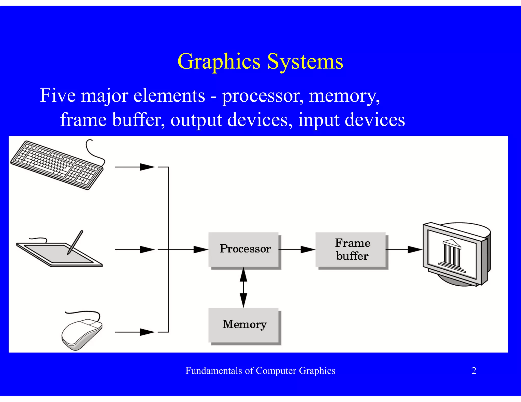
- Graphics systems have major elements like processor, memory, frame buffer, and input/output devices.
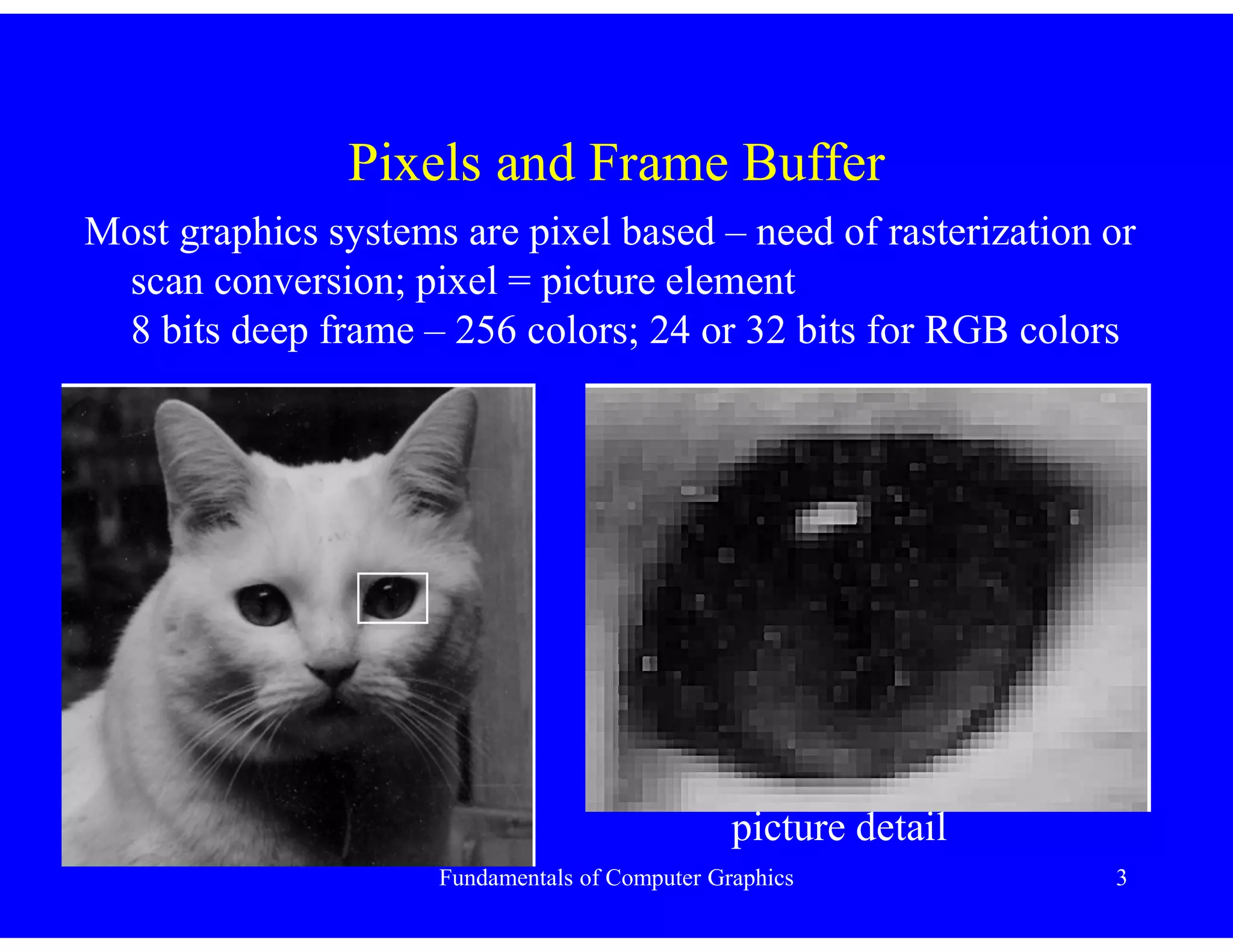
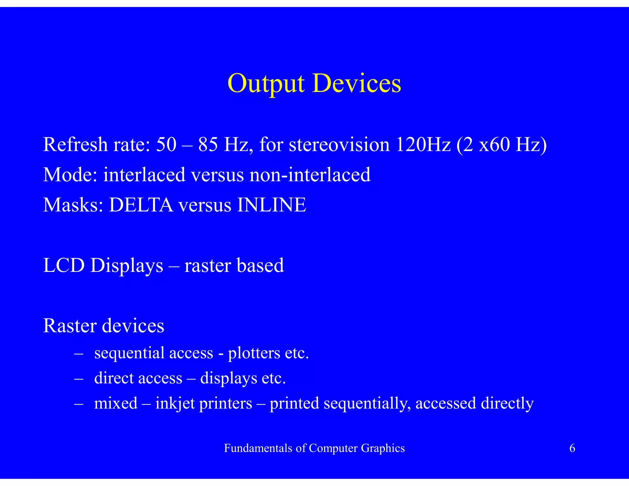
- Pixels and frame buffers are used to display images on raster devices.
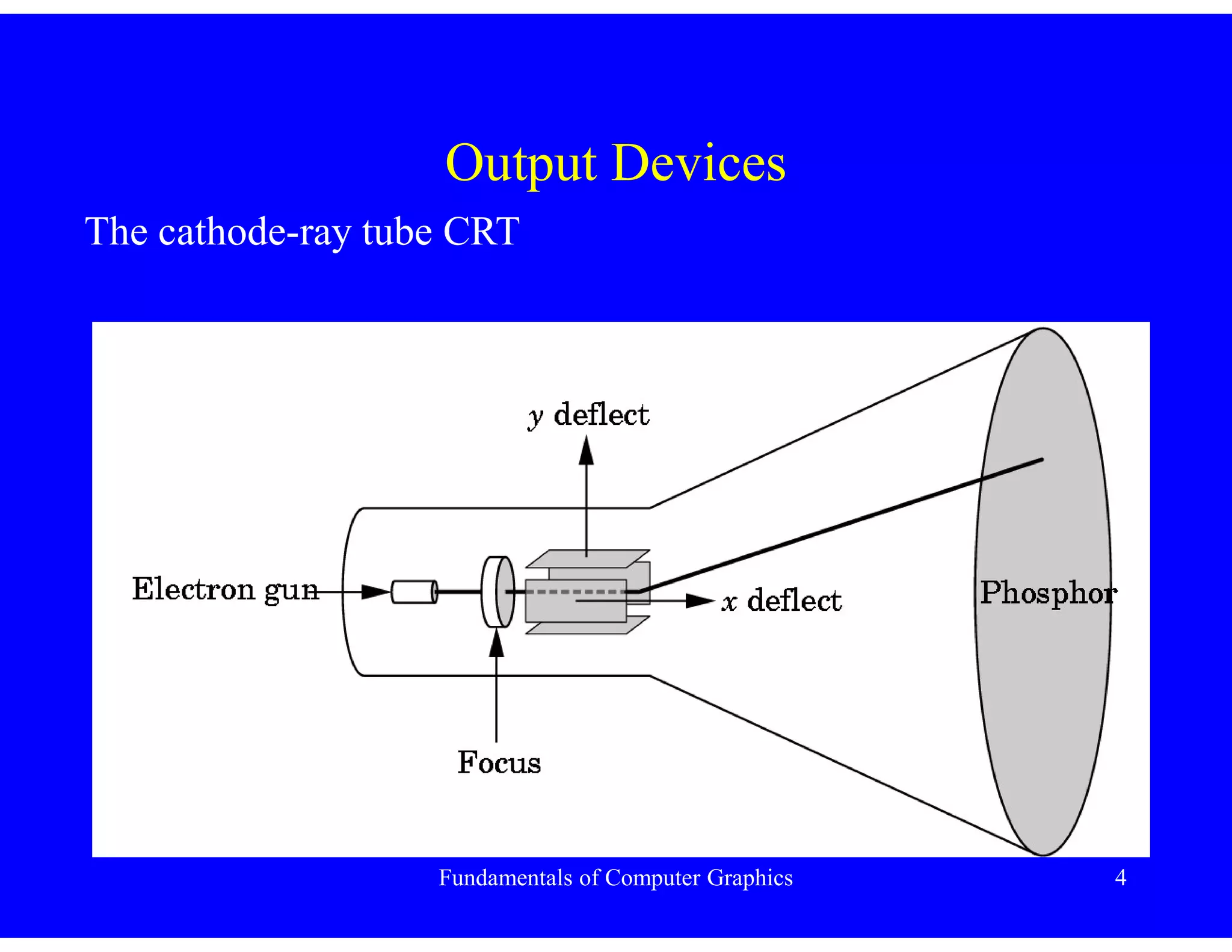
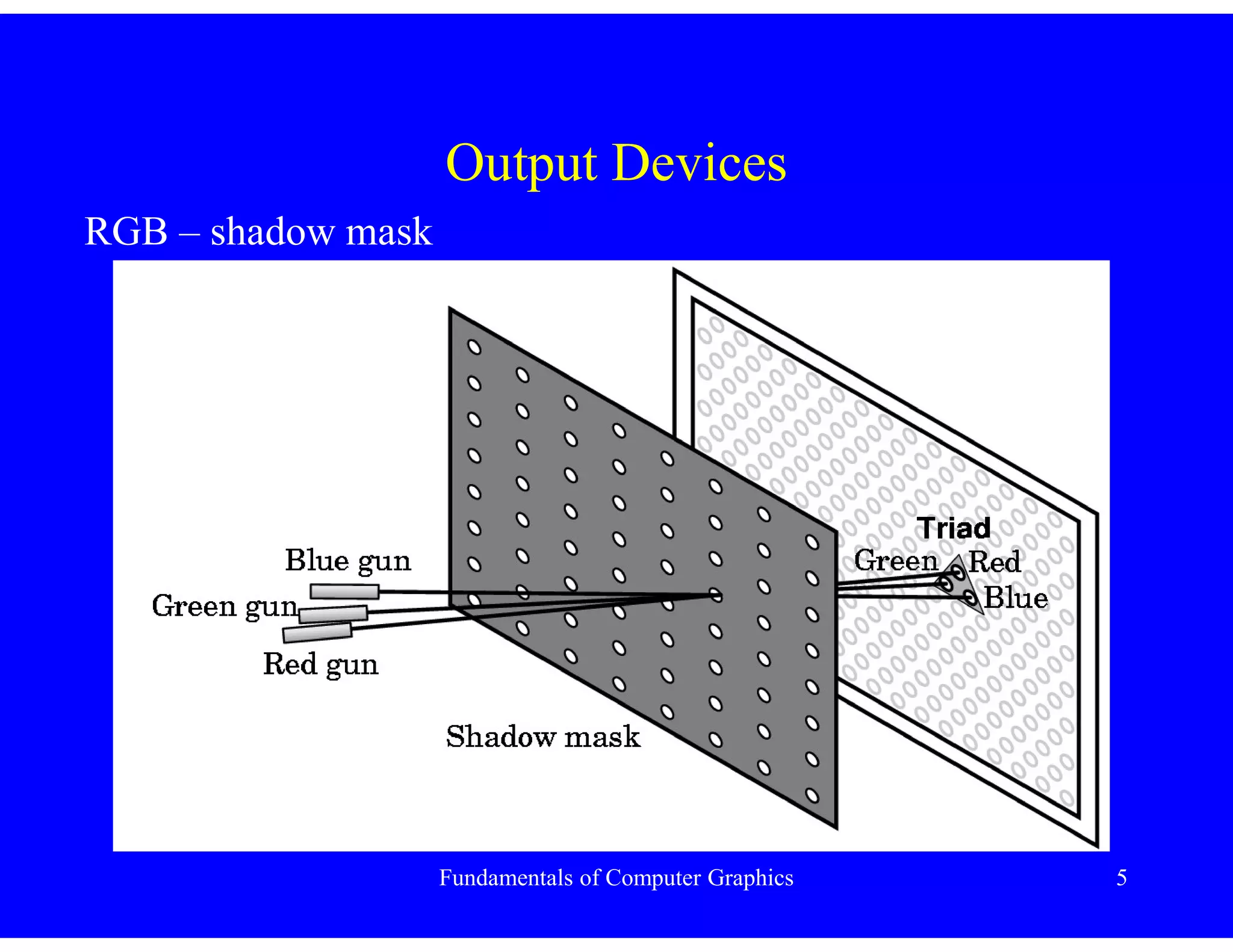
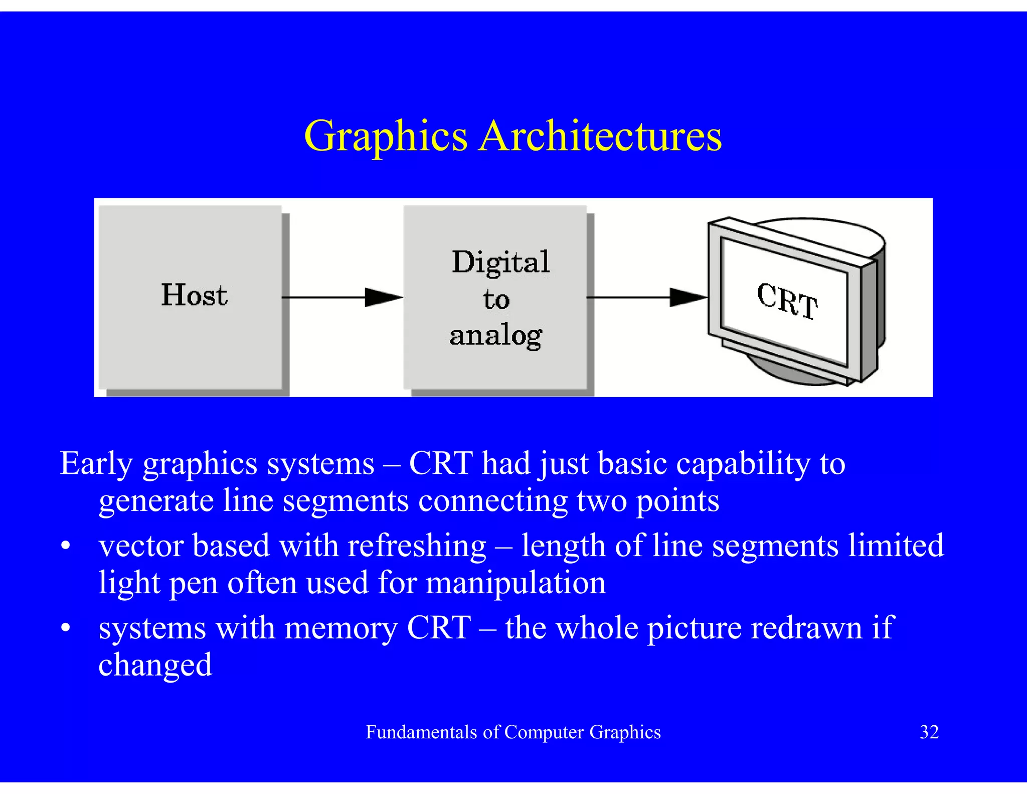
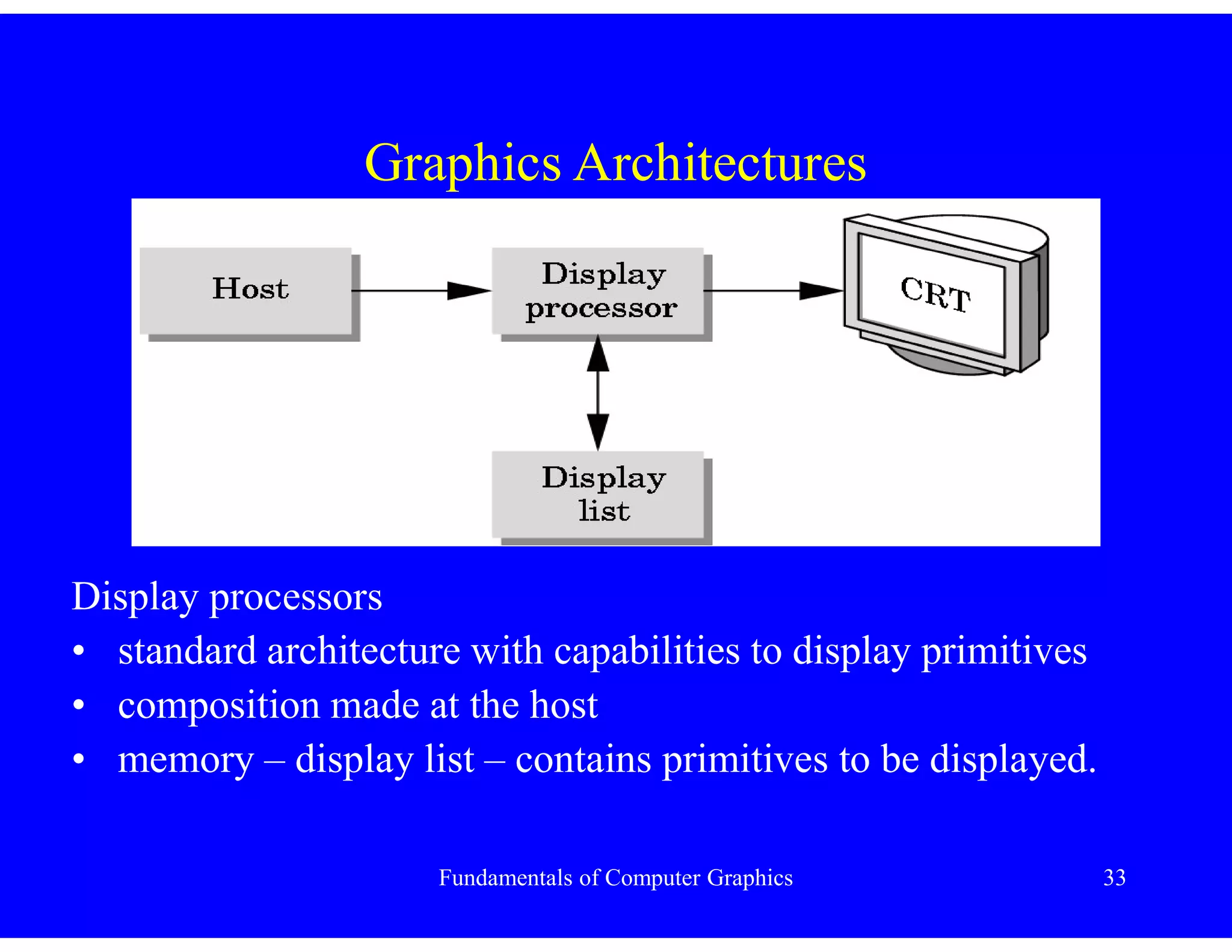
- Output devices like CRT and LCD displays work by refreshing pixels at various rates.
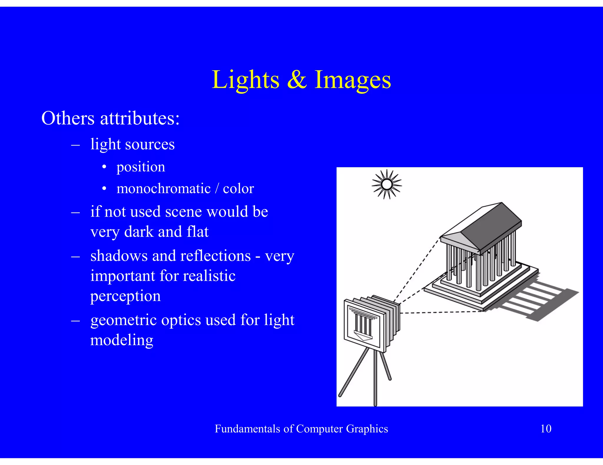
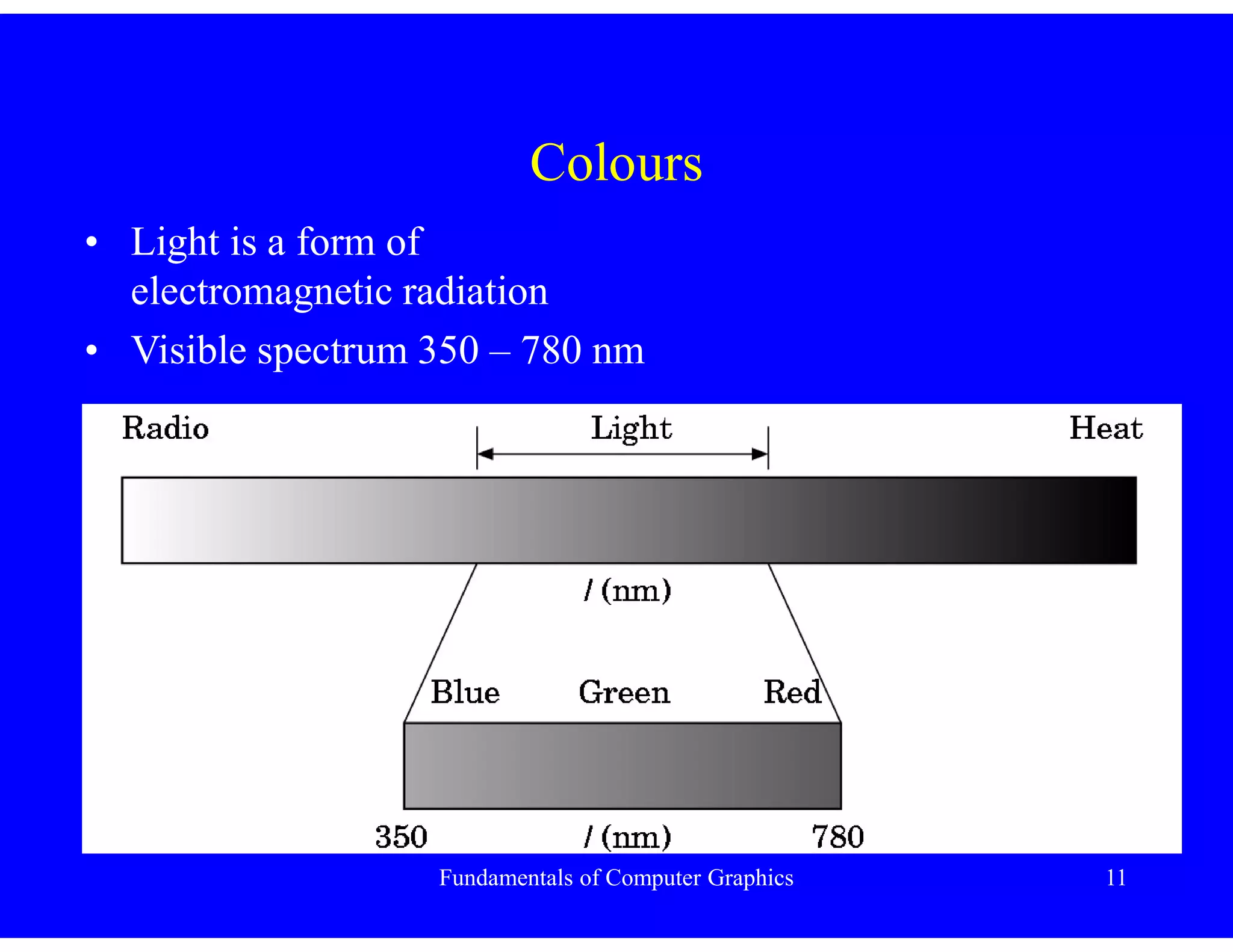
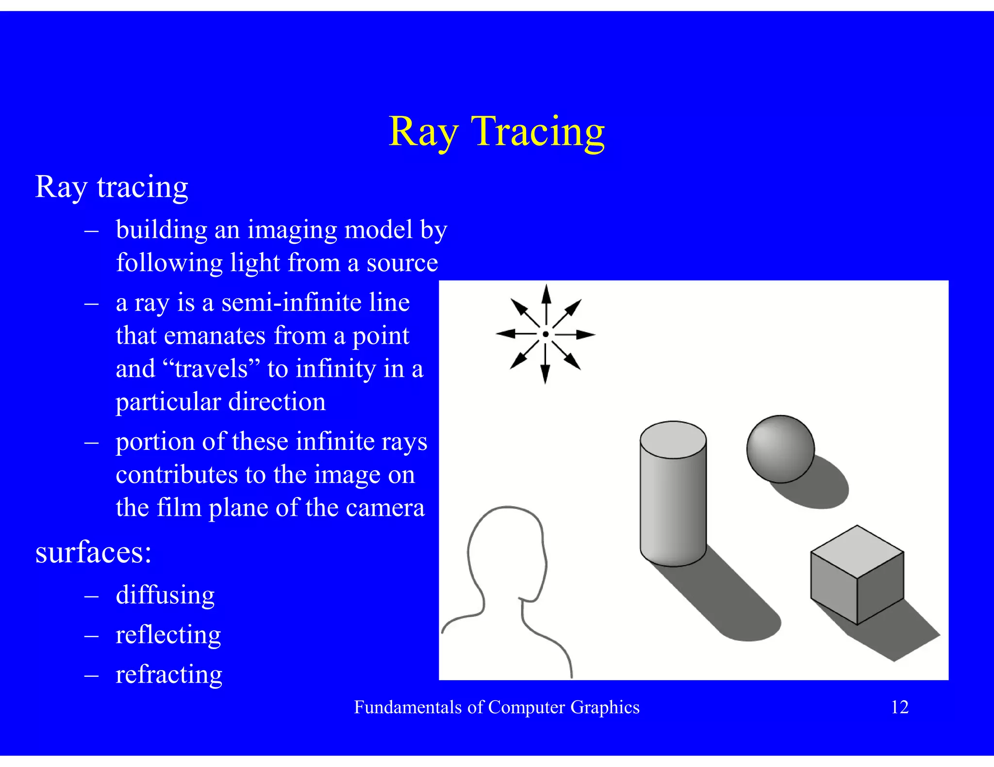
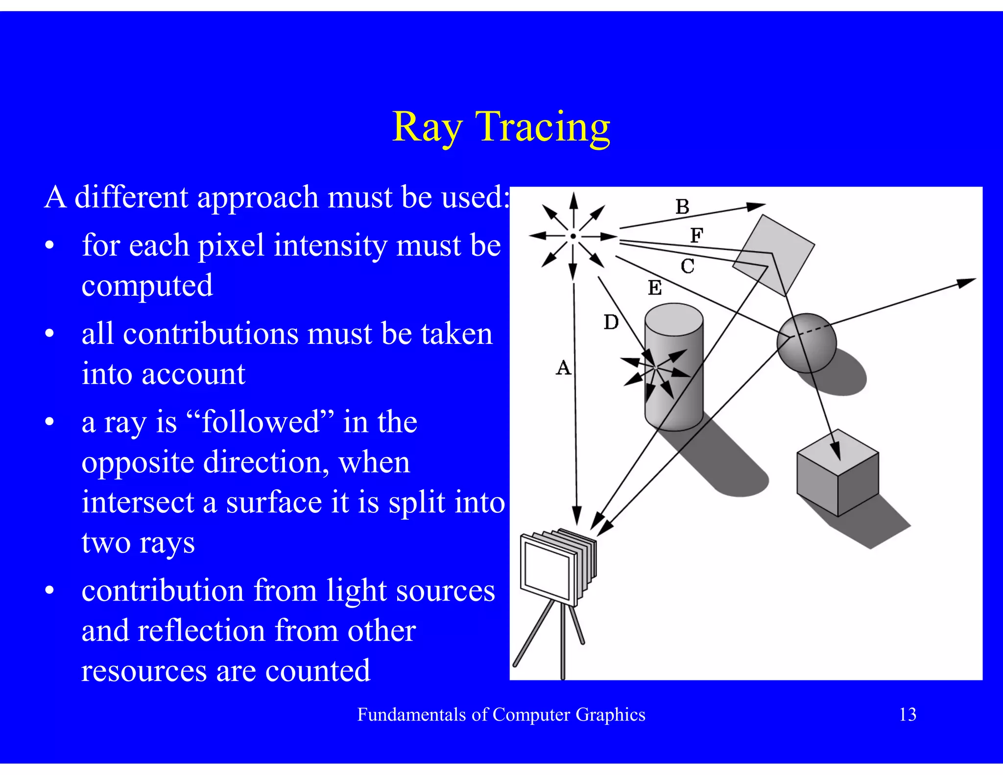
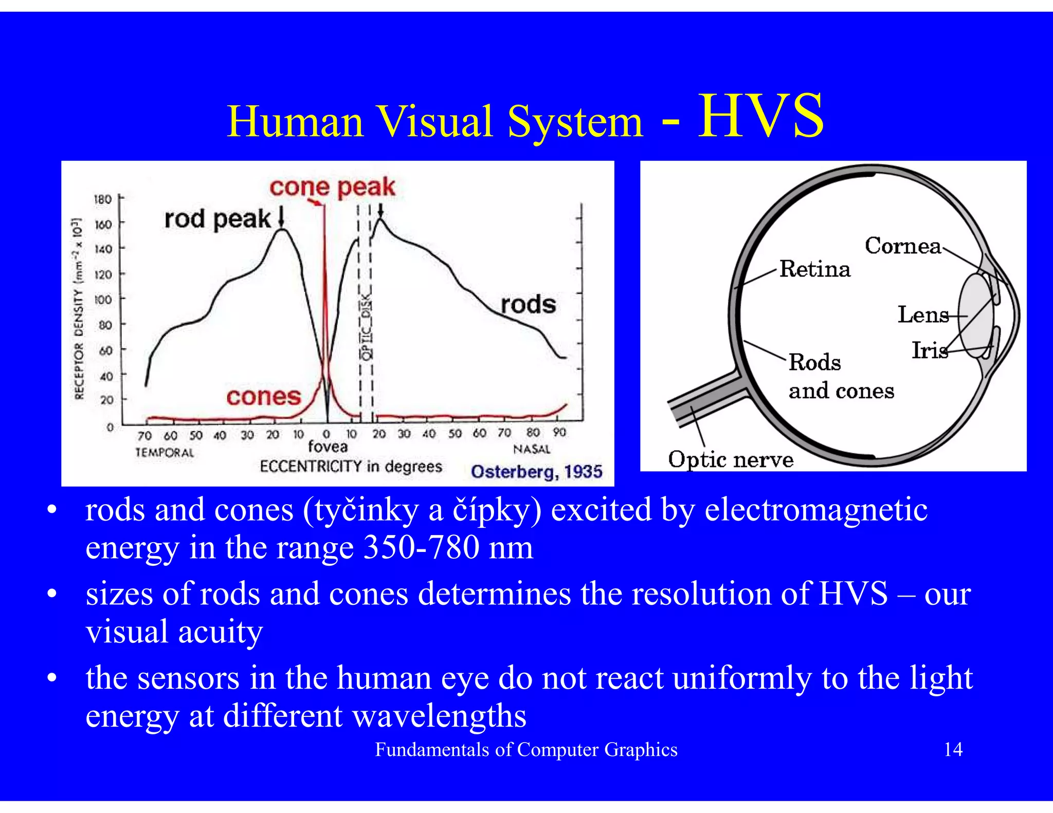
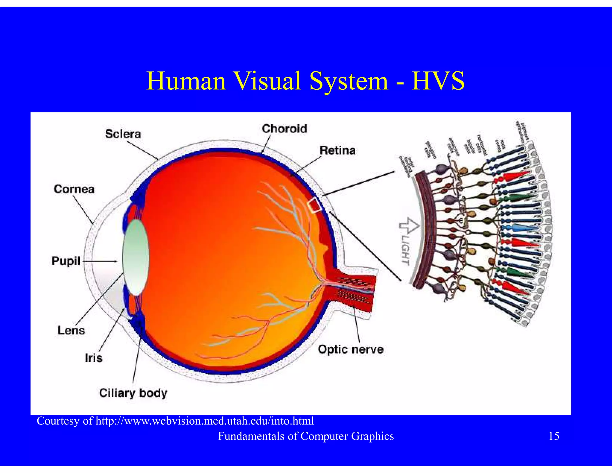
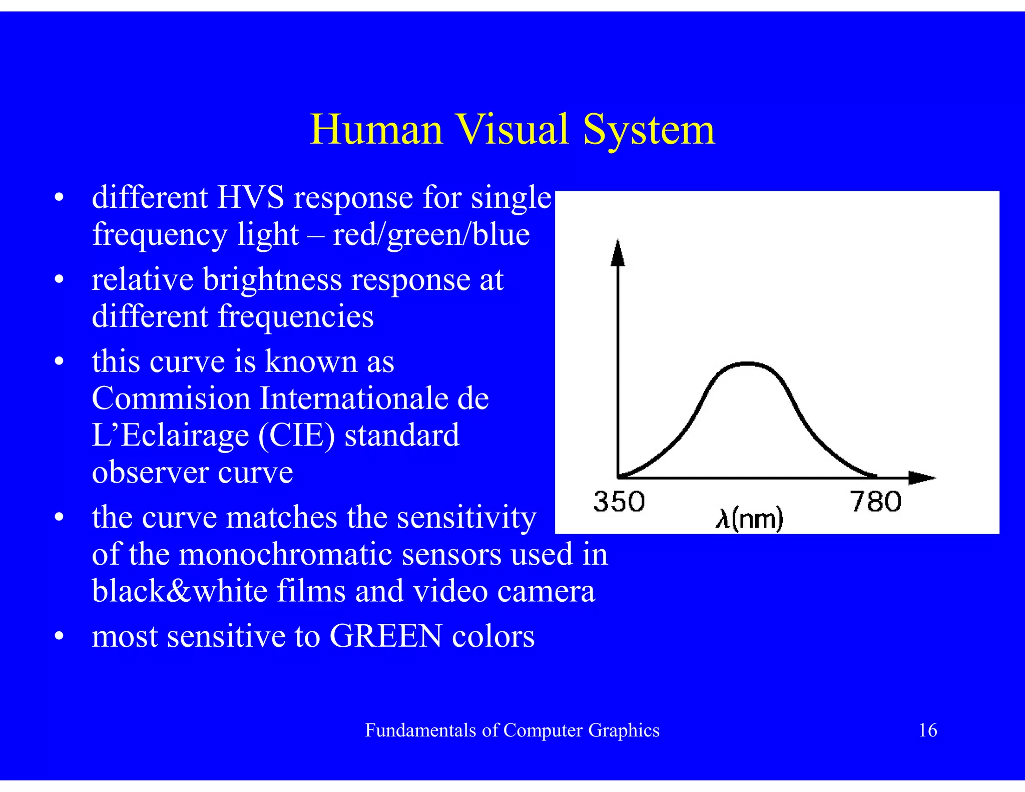
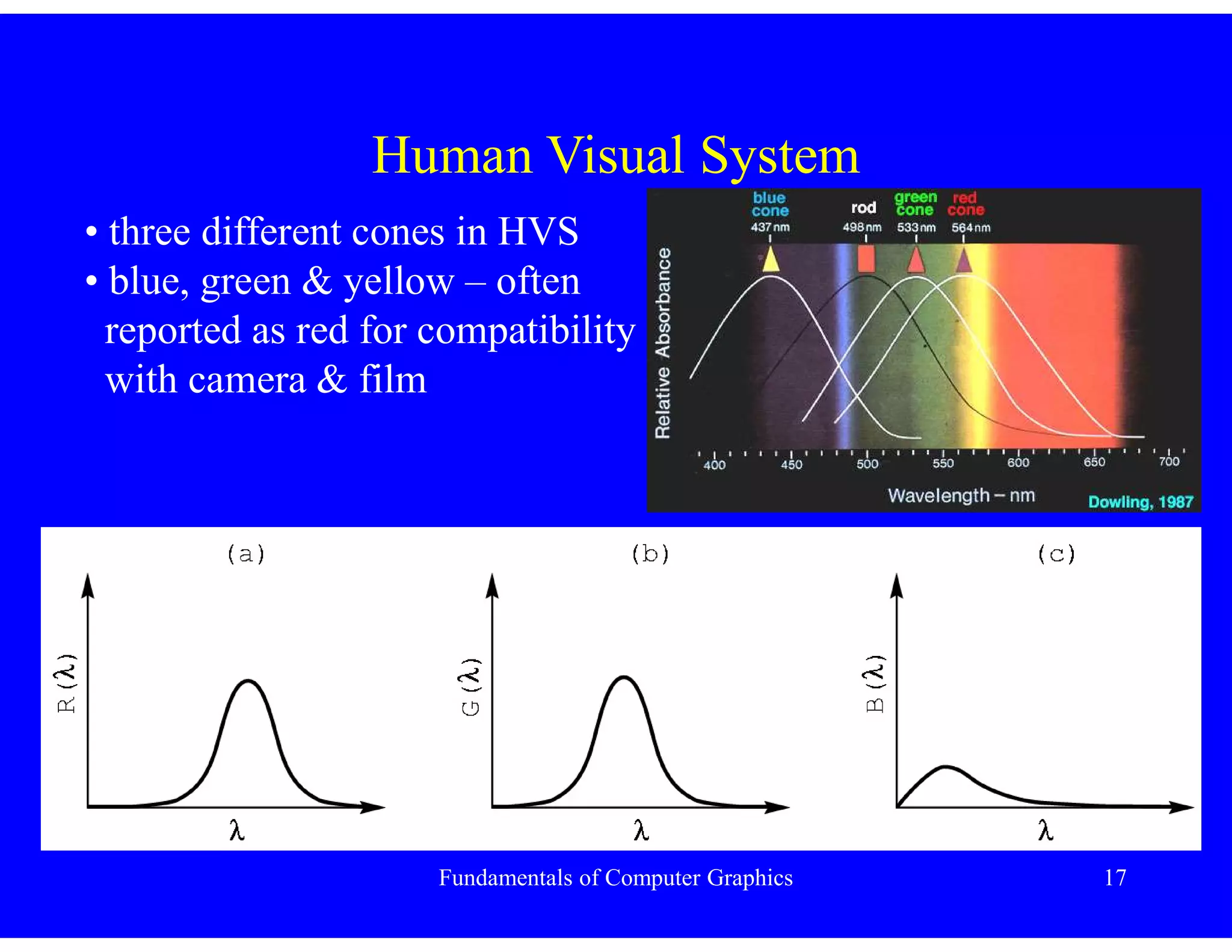
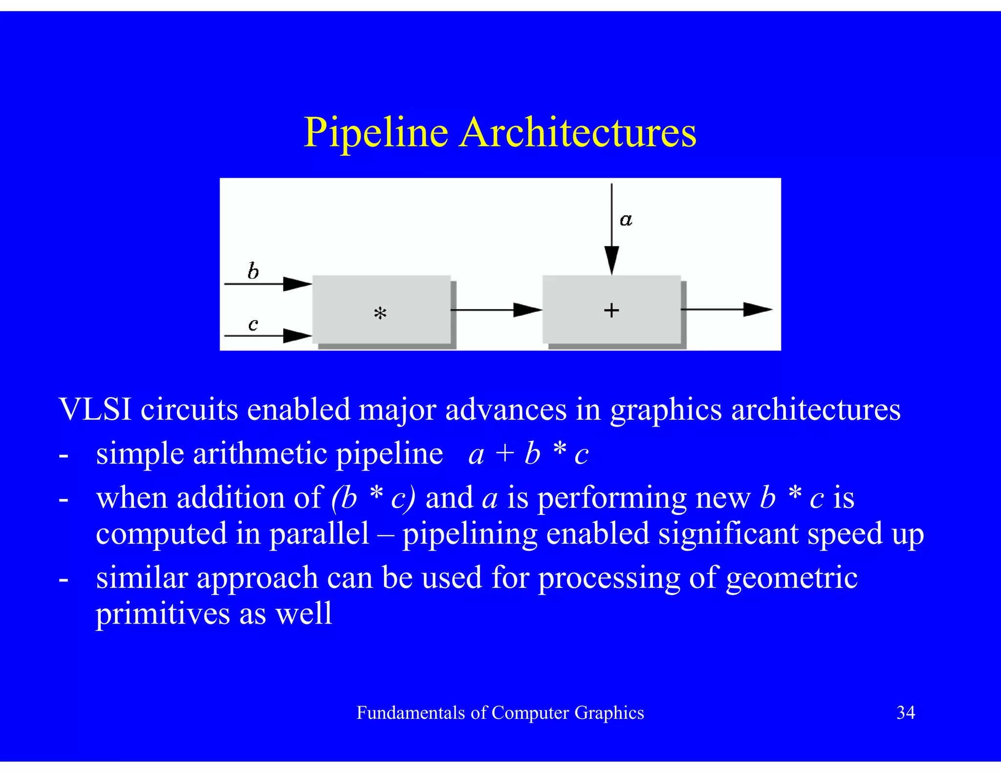
- Ray tracing and the human visual system are described for modeling light and color perception.
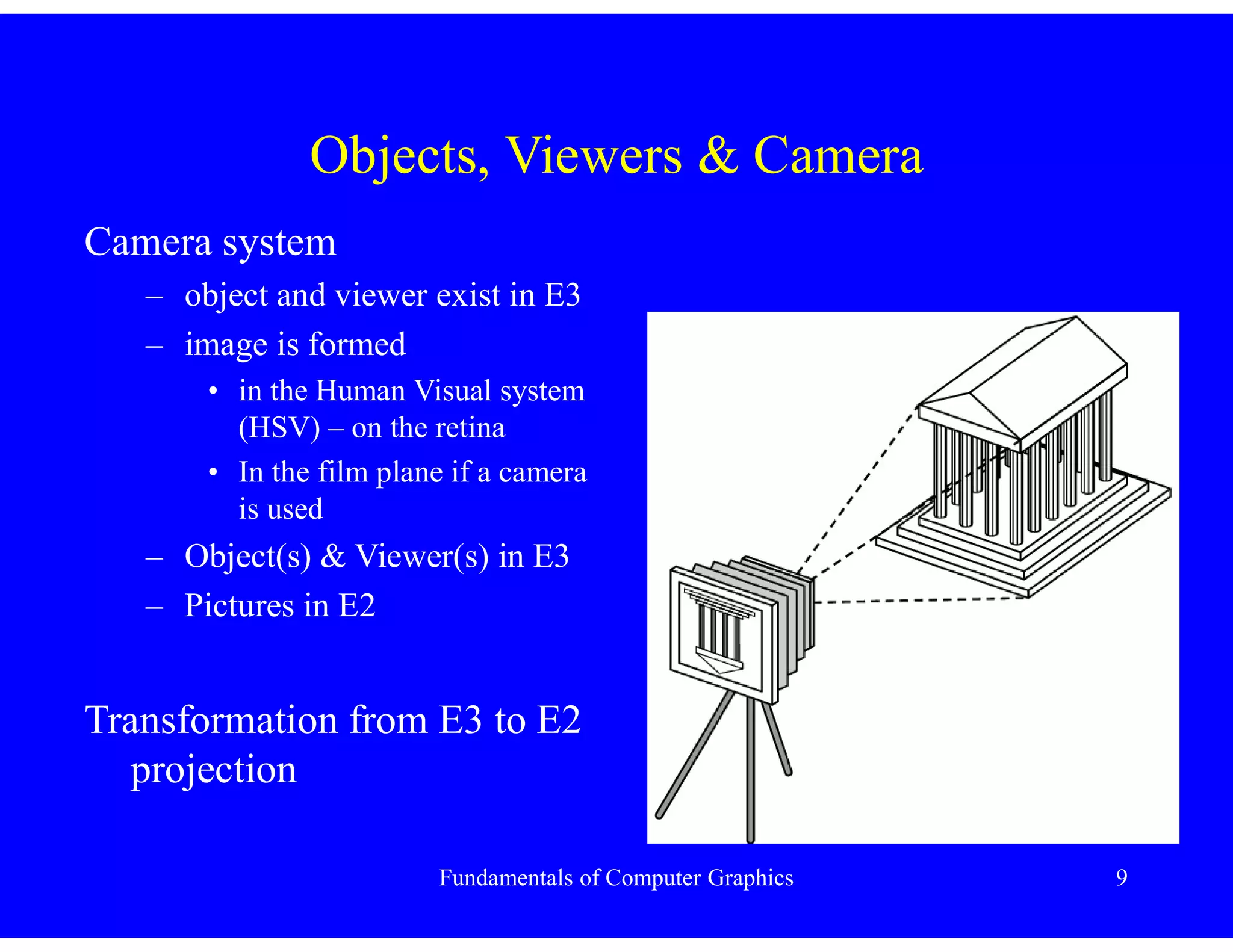
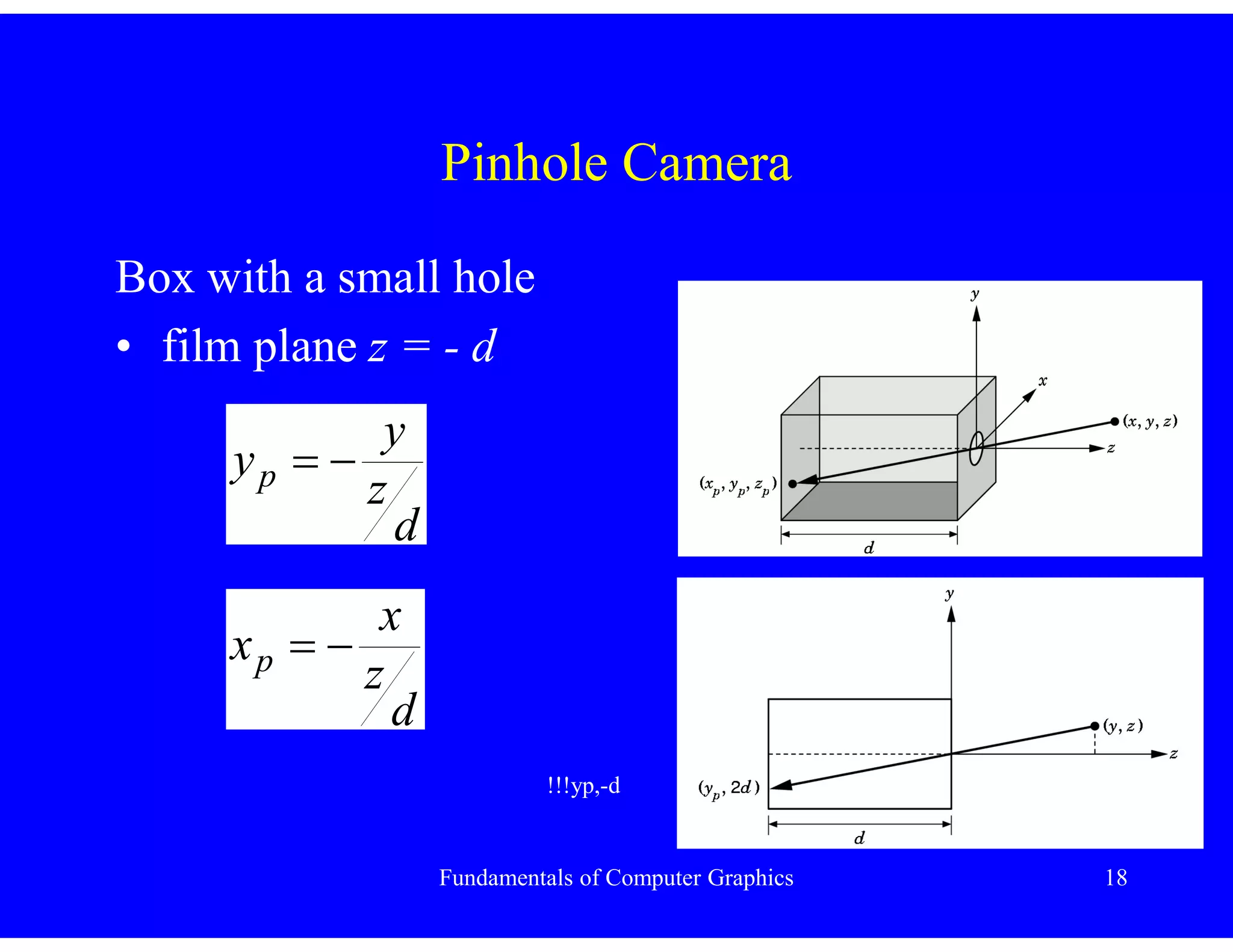
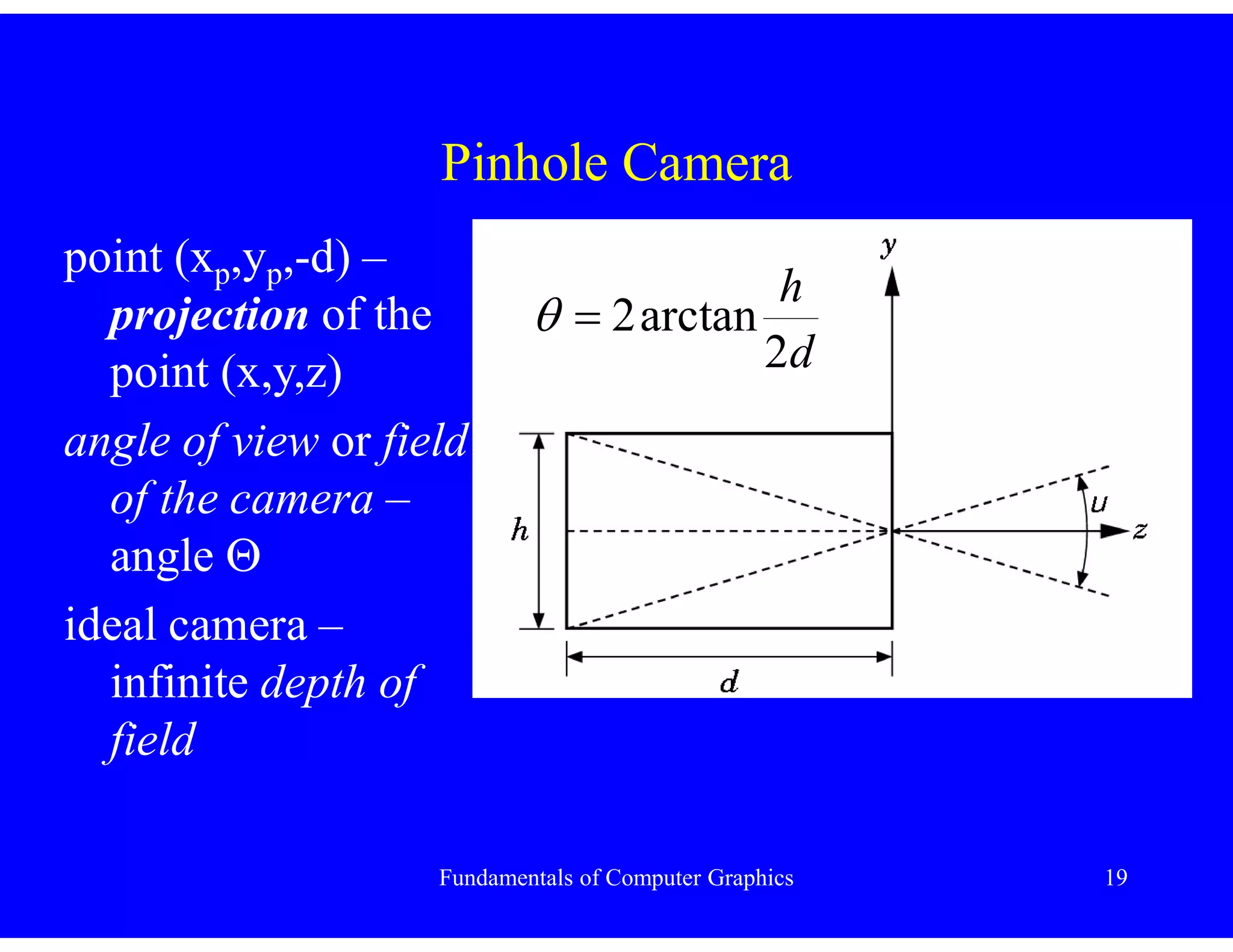
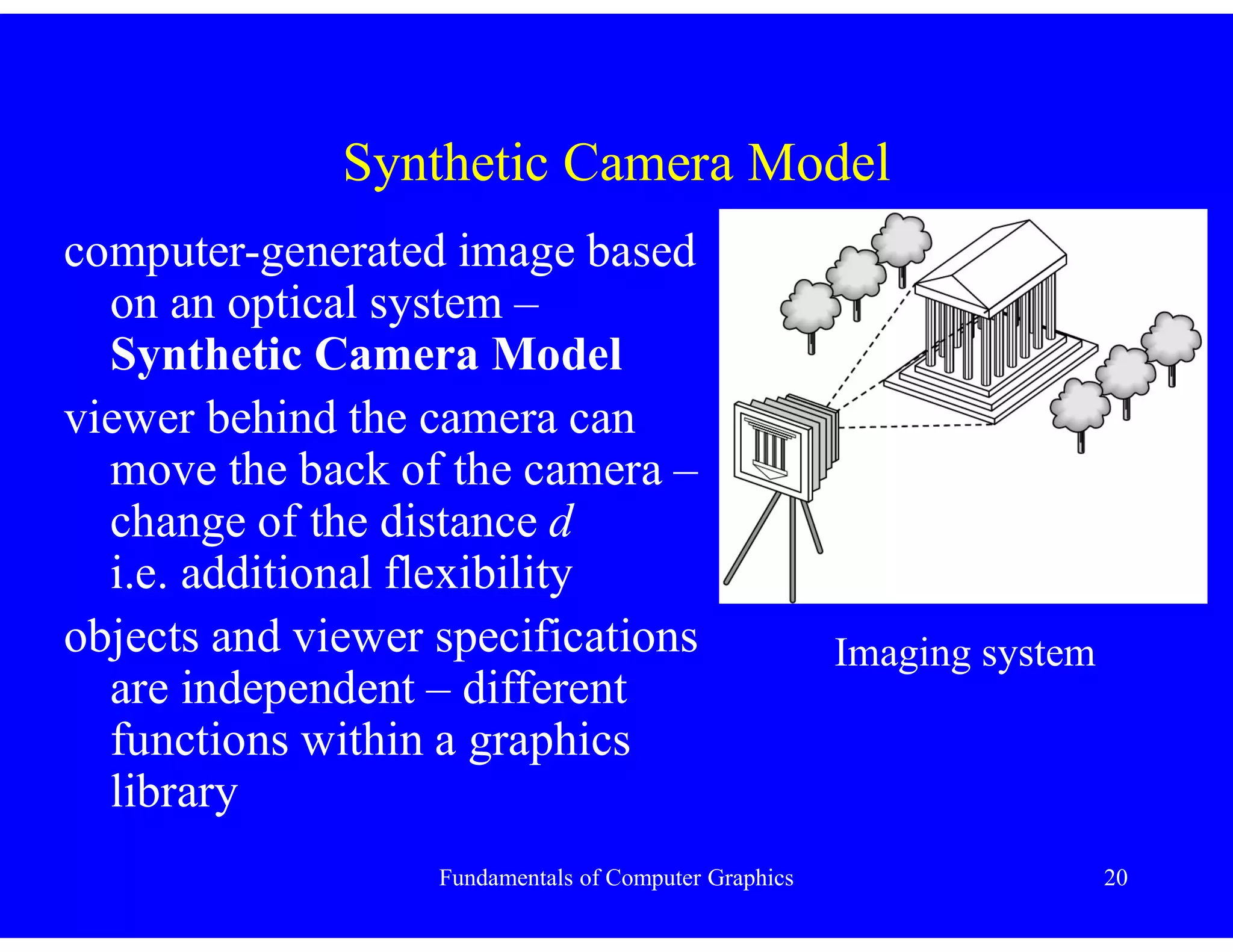
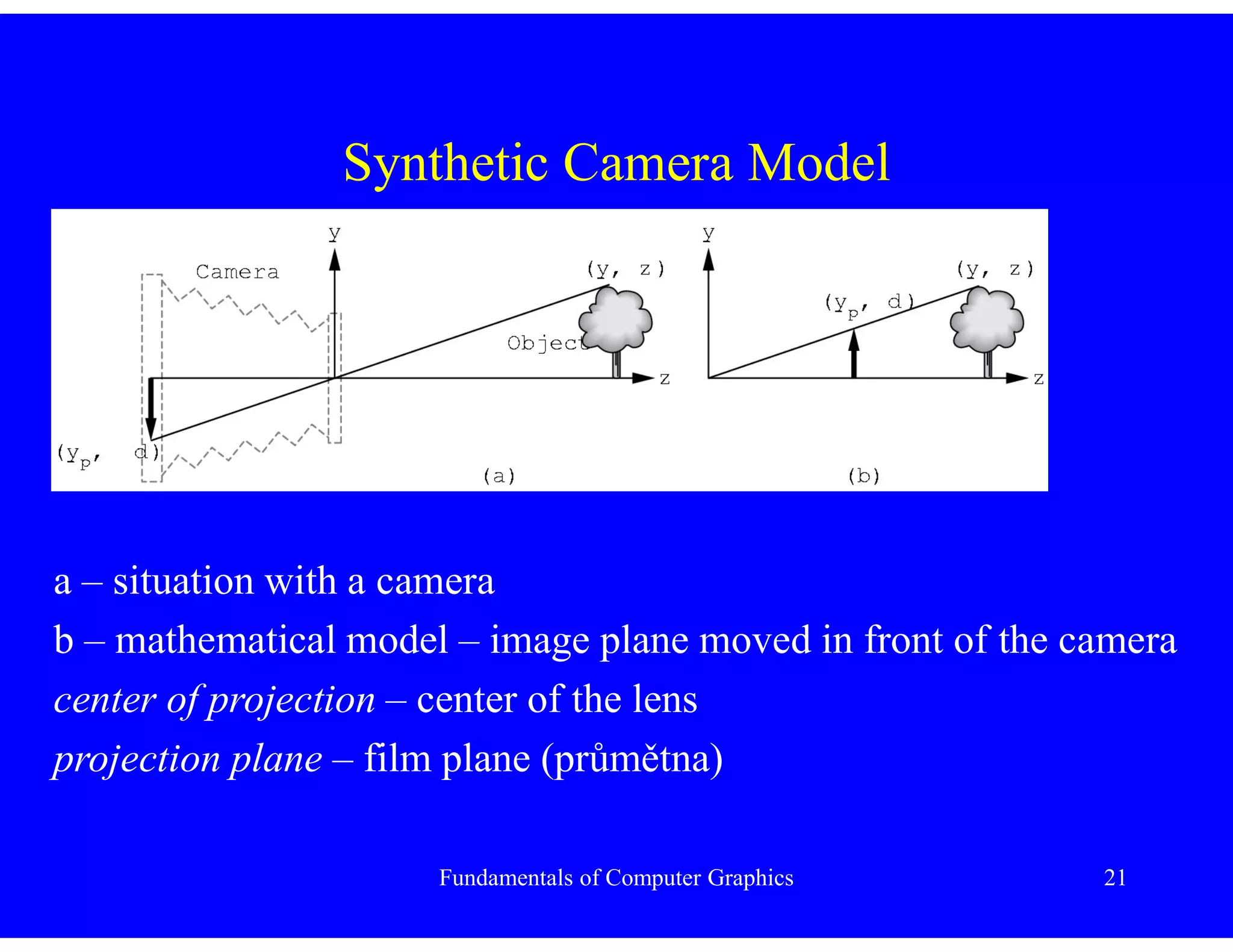
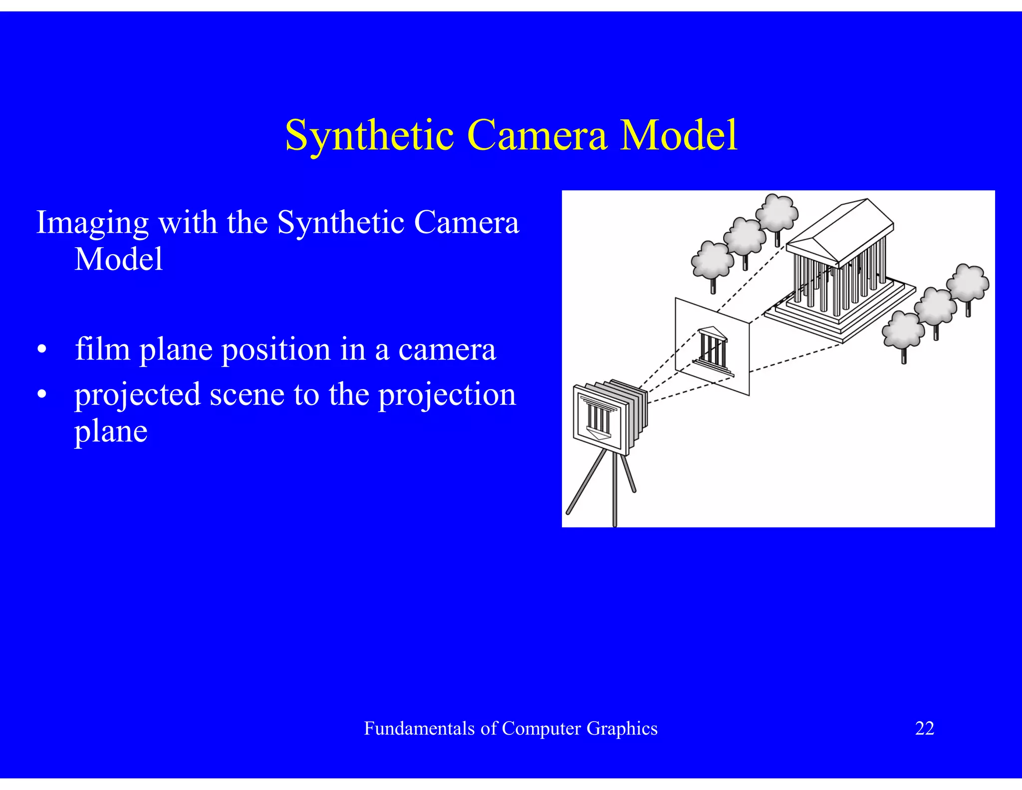
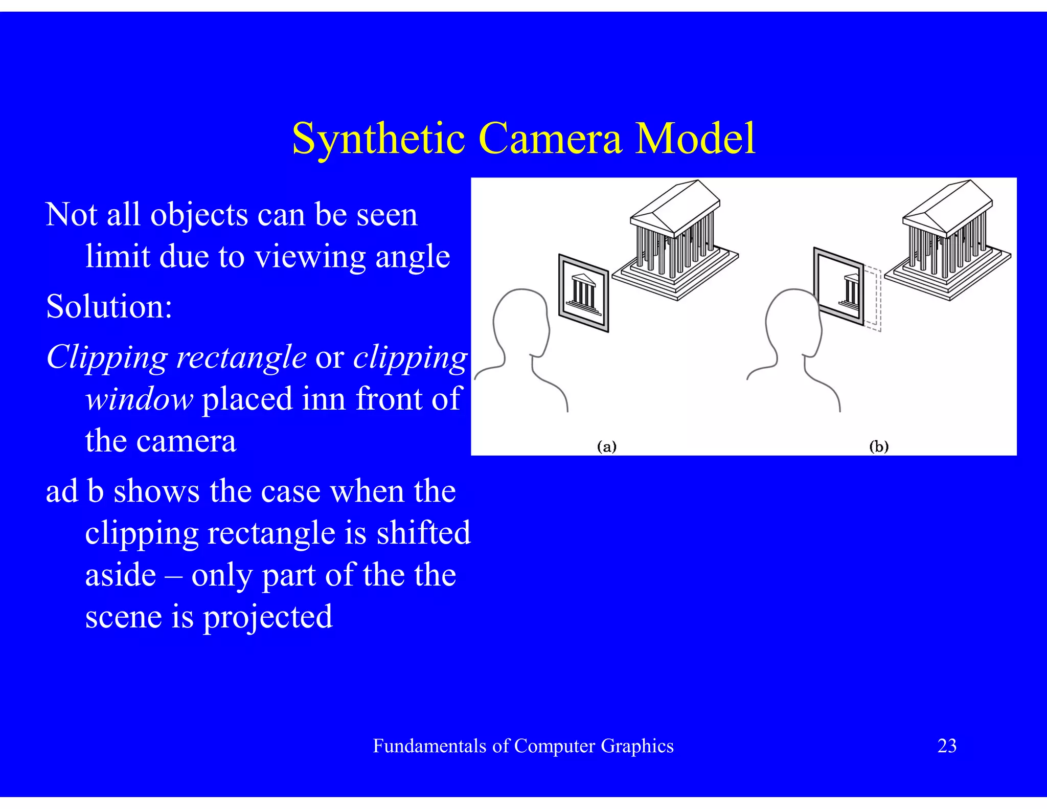
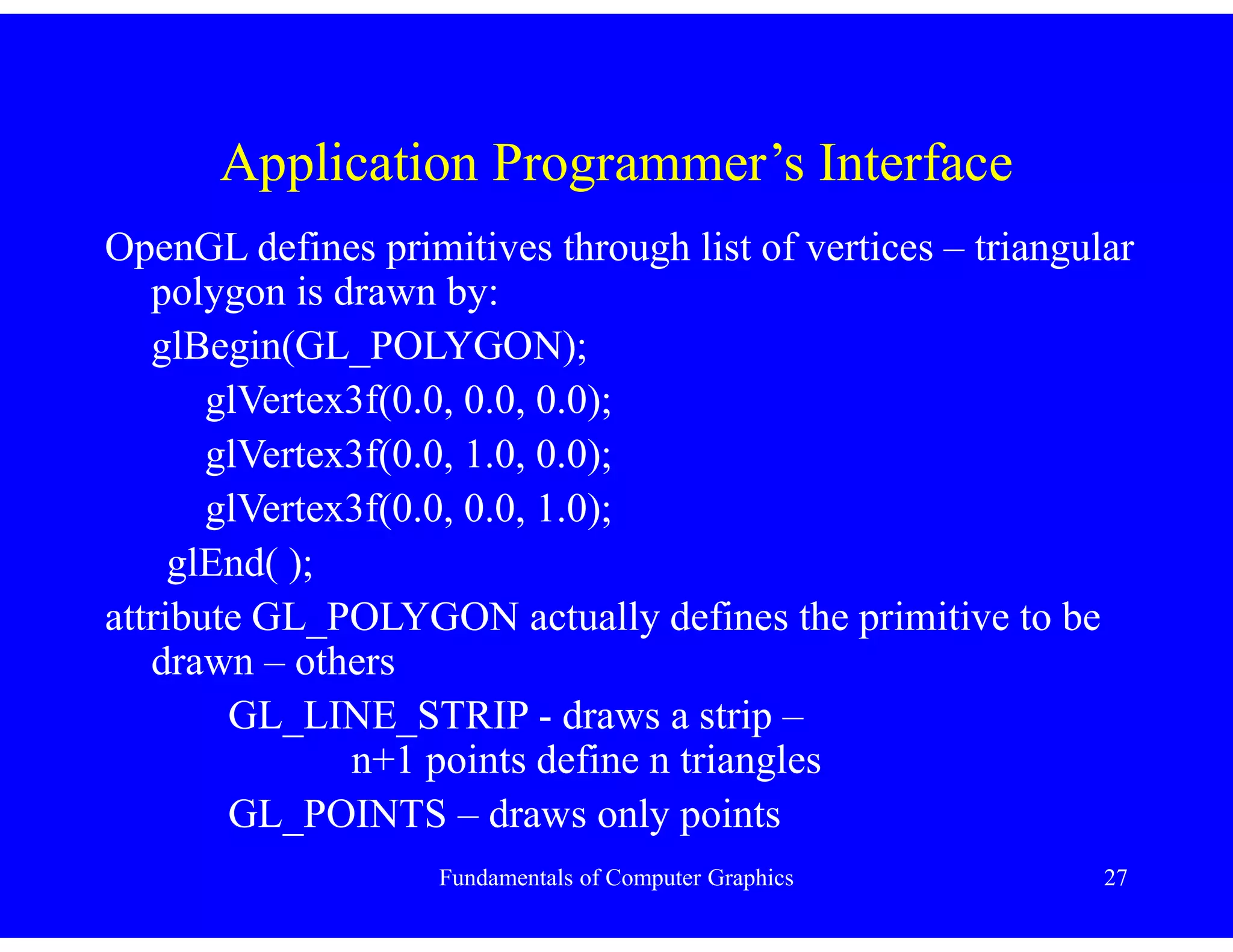
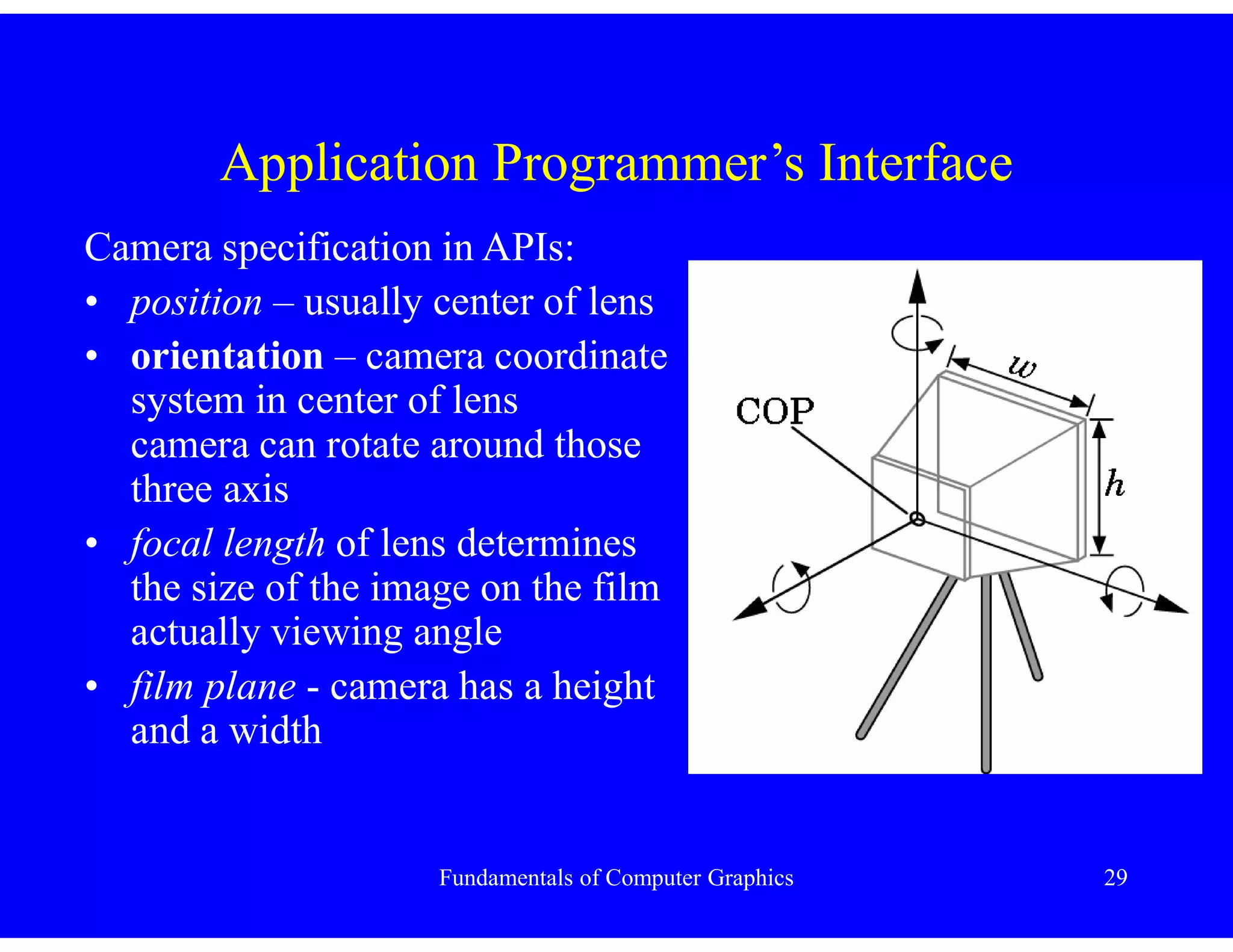
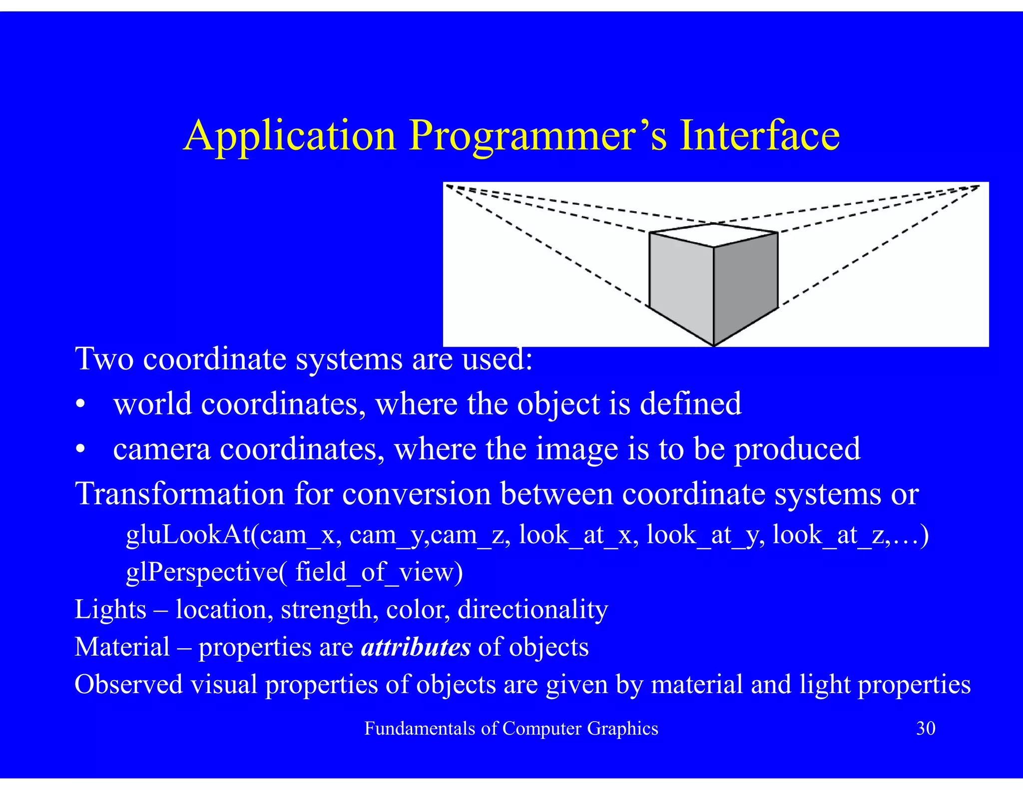
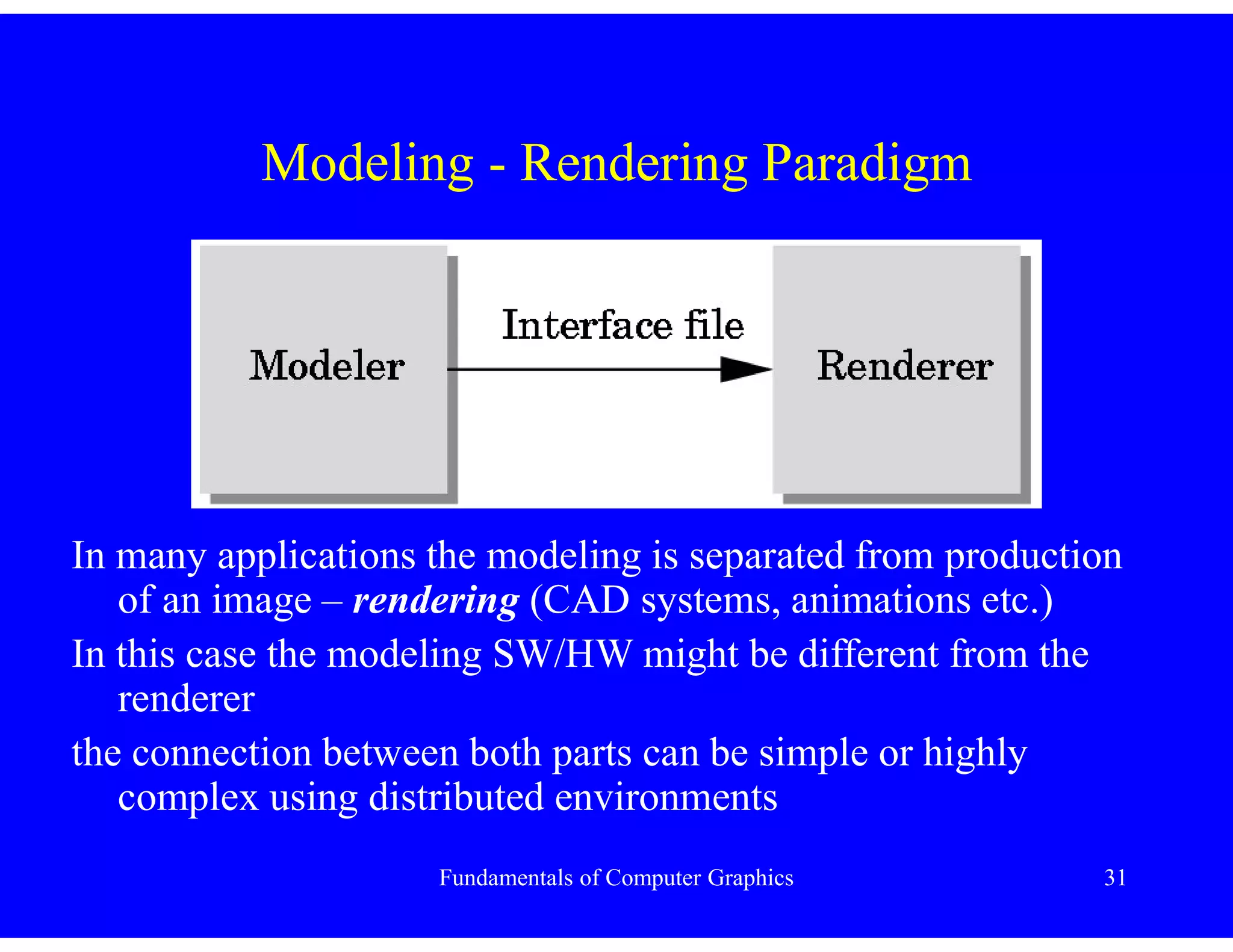
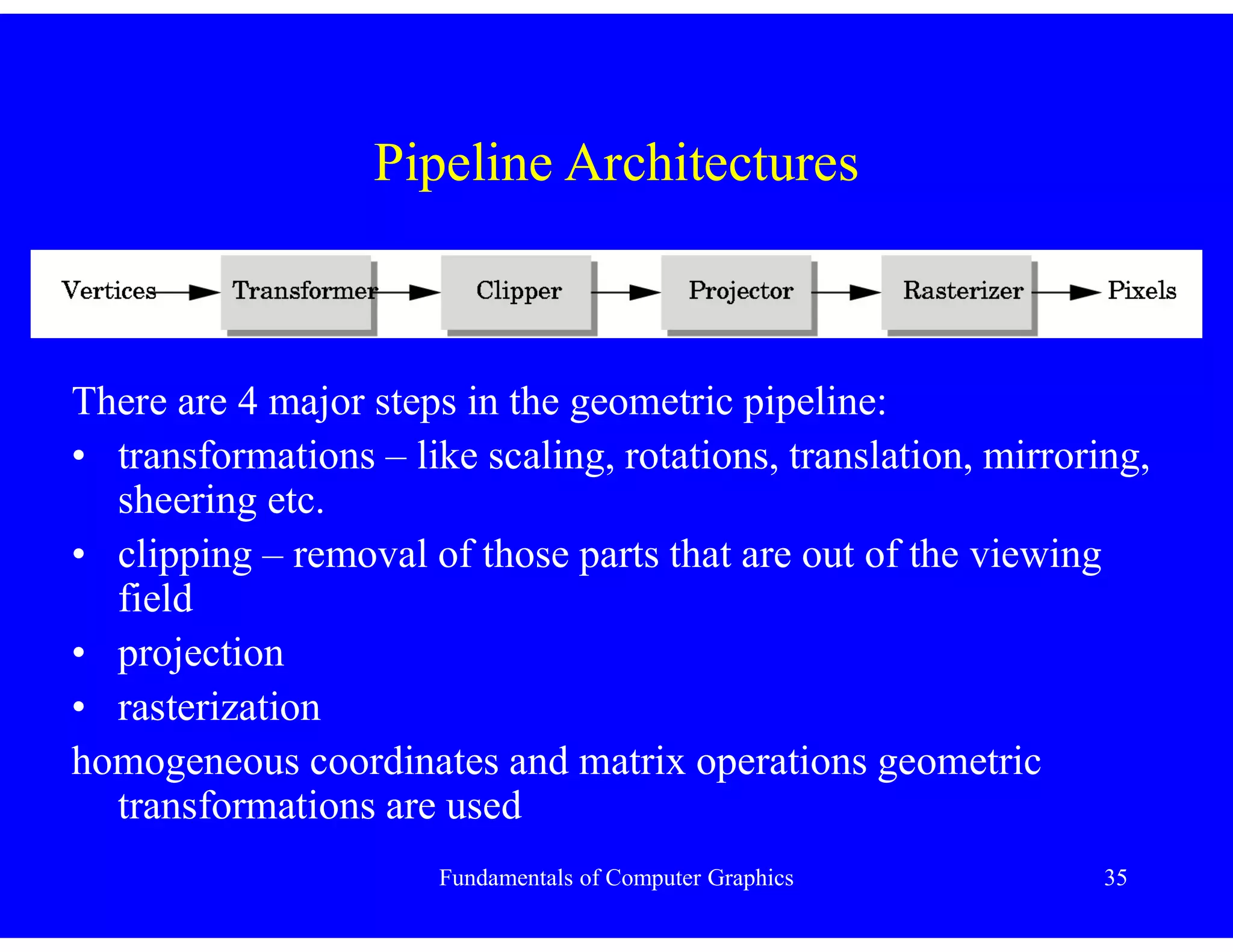
- The synthetic camera model is used in graphics APIs to specify objects, viewers, lights and material properties for rendering 3D scenes.

![Fundamentals of Computer Graphics 39
Exercise No.1 – TRI format
# (data originally from powerflip, not avalon)
# Object name : --- The canonical cow ---
# Number of triangles : 5804
# Number of vertices : 2905
[Vertices]
0.0 0.0 0.0
0.151632 -0.043319 -0.08824 x,y,z coordinates of the j-th vertex
0.163424 -0.033934 -0.08411
0.163118 -0.053632 -0.080509](https://image.slidesharecdn.com/fundamentalsofcomputergraphics-230514021708-1bbff641/75/Fundamentals-of-Computer-Graphics-pdf-39-2048.jpg)
![Fundamentals of Computer Graphics 40
Exercise No.1 – TRI format
[Triangles]
1 2 3 vertex indices forming the i-th triangle
2 4 5
5 4 6
………..
[Triangles' Normals]
0.442 -0.167 -0.881 i-th normal vector for the i-th triangle
0.595 -0.088 -0.798
0.735 -0.093 -0.671
…………………………………………..](https://image.slidesharecdn.com/fundamentalsofcomputergraphics-230514021708-1bbff641/75/Fundamentals-of-Computer-Graphics-pdf-40-2048.jpg)