1. Abstract
Optical tweezers use finely focused lasers to trap tiny particles. This technique is used to
capture biological materials to study them at a single molecule level. The objective of this
research problem was to successfully construct flow cells to hold these biological materials in
an optical tweezers experiment. Biological materials are hard to purify in larger amounts so we
designed a flow cell to use less materials. The core of the flow cell was made up of safety glass
(Plexiglas), where three holes are drilled; one for inlet tubing, one for outlet tubing, and one to
hold the micropipette. After inserting the micropipette into the cell, it was sealed with the
biologically safe optical adhesive and dried with ultraviolet rays. Once the optical tweezers are
built, we will be able to flow micron-size polystyrene beads through this flow cell and trap them
with the lasers. The trapped bead can be attached to the micropipette tip by suction and
moved away from the laser to trap another bead. A single DNA molecule attaches chemically
between these two beads to study various interactions with DNA. We have four inlets for either
DNA, bead, buffer, or drug and one outlet as an exhaust. All this tubing was sealed with the
same adhesive and the exterior was covered with the microscope coverslips. These flow cells
will be used in future optical tweezers experiments at BSU.
Sealing the Core Cell Inserting the Micro Pipette Tip
1. Biologically safe optical adhesive is applied to
one sides of the machine designed core of the
flow cell made of safety glass (Plexiglass)
evenly without entering the open cell space..
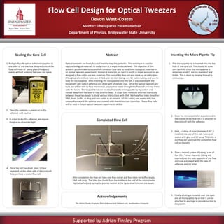
After completion the flow cell have one flow out let and four inlets for buffer, beads,
DNA and drugs. The tube that heads from the middle at the end of the micropipette
tip is attached to a syringe to provide suction at the tip to attach micron size beads.
2. Then the coverslip is placed on to the
adhesive with caution.
Flow Cell Design for Optical Tweezers
Devon West-Coates
Mentor: Thayaparan Paramanathan
Department of Physics, Bridgewater State University
Supported by Adrian Tinsley Program
3. In order to dry this adhesive, we expose
the glue to ultraviolet light.
4. Once the cell has dried, steps 1-3 are
repeated on the other side of the core cell.
Now we have a sealed flow cell.
Acknowledgements
1. The micropipette tip is inserted into the top
hole of the core cell. This should be done
very carefully since the micropipette is
extremely small (1 micron diameter) and
brittle. This is done by viewing through a
microscope.
2. Once the micropipette tip is positioned in
the middle of the flow cell it is attached to
the core cell with the adhesive.
3. Next, a tubing of inner diameter 0.45” is
installed into one of the side holes and
sealed with glue and UV lamp. This tube is
our flow out tube (see the completed flow
cell on the left)
The Adrian Tinsley Program, Patricia Benson and Williams Lab, Northeastern University
4. Then a second system of tubing, a set of
four 0.11 “ inner diameter tubing are
inserted into the hole opposite of the flow
out tube and sealed with the help of
adhesive and UV lamp.
5. Finally a tubing is installed over the open
end of micropipette tip so that it can be
attached to a syringe to provide suction to
the pipette.
Completed Flow Cell