Bicycle Deceleration Indicator 
Team 13 
Final Report 
May 3, 2016 


Bryan Sellers 
ECE BOX 300 
 
Aidan Lippert 
ECE BOX 179 
 
Brian Mitchell 
ECE BOX 218 


Table of Contents 
 
 
1 
1.1 
1.2 
1.2.1 
1.2.2 
1.2.3 
1.2.4 
 
2 
2.1 
2.2 
2.3 
2.3.1 
2.3.2 
2.3.3 
2.3.4 
 
3 
3.1 
3.1.1 
3.1.2 
3.1.2.1 
3.1.2.2 
3.1.2.3 
3.1.2.4 
3.2 
3.2.1 
3.2.1.1 
3.2.1.2 
3.2.1.3 
3.2.2 
3.2.2.1 
3.2.2.2 
3.2.2.3 
3.2.3 
Introduction 
Problem Statement 
Market Research 
Targeted Market 
Research Methods 
Research Results 
Research Conclusions 
 
Product Requirements 
Customer Requirements 
Product Specifications 
Competitive Value Analysis 
Essential Customer Criteria 
Metrics for Value Analysis 
Competitors 
Value Analysis 
 
Design Approach 
System Architecture 
Design Overview 
Modular Overview 
Power Generation 
AC/DC Conversion 
Digital Control 
Indicator Output 
Module Definition 
Power Generation Module 
Description of Functions 
Module Input 
Module Output 
AC/DC Conversion Module 
Description of Functions 
Module Input 
Module Output 
Digital Control Module 
5 
5 
5 
5 
5 
6 
7 
 
8 
8 
8 
9 
9 
12 
13 
20 
 
22 
22 
22 
22 
22 
23 
23 
24 
24 
24 
24 
25 
25 
27 
27 
29 
29 
29 
 
1 
3.2.3.1 
3.2.3.2 
3.2.3.3 
3.2.4 
3.2.4.1 
3.2.4.2 
3.2.4.3 
3.2.5 
3.2.5.1 
3.2.5.2 
3.2.5.3 
3.2.5.4 
3.2.2.5 
3.2.5.6 
 
4 
4.1 
4.2 
4.2.1 
4.2.2 
4.2.3 
4.2.4 
4.2.5 
 
5 
5.1 
5.2 
 
6 
6.1 
6.2 
 
7 
 
8 
 
Appendix A 
Appendix B 
Description of Functions 
Module Input 
Module Output 
Indicator Output 
Description of Functions 
Module Input 
Module Output 
System Integration 
Power Generation 
AC/DC Conversion 
Indicator Output 
Digital Control 
Full System Integration 
System Testing 
 
Product Testing 
Product Functionality 
System Testing and Results 
Power Generation Module Testing 
AC/DC Conversion Module Testing 
Digital Control Module Testing 
Indicator Output Module Testing 
Integrated System Testing 
 
Cost Analysis 
Initial Investment 
Return on Investment (ROI) 
 
Failure and Hazard Analysis 
Internal Threats 
External Threats 
 
Recommendations 
 
Conclusions 
 
Parts List 
Computer Code   
29 
30 
30 
30 
30 
31 
31 
31 
32 
32 
32 
32 
32 
33 
 
34 
34 
34 
34 
34 
36 
36 
37 
 
41 
41 
41 
 
42 
42 
42 
 
43 
 
44 
 
45 
46 
 
2 
Table of Figures 
 
1. 
2. 
3. 
4. 
5. 
6. 
7. 
8. 
9. 
10. 
11. 
12. 
13. 
14. 
15. 
16. 
17. 
18. 
19. 
20. 
21. 
22. 
23. 
24. 
25. 
26. 
27. 
28. 
Friction Generator Dynamo 
Red LED 
Generic Accelerometer Module 
Rear Bike Light Bicycle Laser Beam Rear Tail Light 
Rear Bike Light Specifications 
Basecamp Rear Bike Light Remote Control 
Rear Bike Light Specifications (2) 
Front Bike Light 5­LED Black Bicycle Headlight 
Front Bike Light Specifications 
Front Bike Light, HeadLamp Kit 
Front Bike Light Specifications (2) 
Brakeless Deceleration Indicator 
Top Level Diagram 
Schematic of Dynamo 
Speed vs. Output Power Graph 
Schematic of the AC/DC Conversion Module 
Schematic of Digital Control Module 
Schematic of Indicator Output Module 
AC/DC Conversion 
AC/DC Conversion Multimeter Reading 
Digital Control Module Testing 
LED Output 
Three­Module System Test 
Three Module System on Single Breadboard 
Mounted System on Bicycle 
Bicycle Test Run 
ROI Analysis 
Digital Control Code 
9 
9 
9 
14 
14 
15 
16 
17 
17 
18 
19 
20 
22 
25 
26 
28 
30 
31 
35 
35 
36 
37 
38 
38 
39 
40 
41 
48 


3 
Table of Tables 
 
1. 
2. 
3. 
4. 
5. 
6. 
7. 
8. 
9. 
Competitive Value Analysis 
Power Generation 
AC/DC Conversion 
Digital Control 
Indicator Output 
Dynamo Specifications 
Dynamo Temperature Test 
Specifications of the Voltage Regulator 
Parts List 
20 
22 
23 
23 
24 
26 
27 
28 
45 
   
 
4 
1. Introduction 
 
1.1 ­ ​Problem Statement 
 
The course design challenge was to conceive of, design, and develop a useful product with the 
following parameters: 
● Harvests stray energy from its environment 
● Senses some parameter within that environment 
● Provides some level of safety to the user 
● Costs less than $50 
 
The objective was to design a device that provides visibility for a bicycle and that automatically 
notifies others nearby if the cyclist is slowing down. The purpose of the device is to improve the cyclist’s 
safety and to prevent accidents.  
 
 
1.2 ­ ​Market Research 
 
Research was conducted to understand the needs of the product and the viability of the market. 
Current products with similar components were consulted, reaffirming the desire for an improved product. 
The conceived design exhibits promise to be successful in the current market. 
 
1.2.1 ­ ​Targeted Market 
 
The market for this product are people who use bicycles for daily transportation. According to the 
U.S. Department of Transportation, an estimated 500,000 people are included in this targeted market.  1
 
1.2.2 ­ ​Research Methods 
 
Several databases were utilized while conducting market research, each available through the 
WPI Library. Google Scholar was our primary resource due to its accessible collection of patents. Current 
products in the market with similar components to our design were identified. These similar products 
were analyzed to improve the functionality of the chosen design, allowing us to improve upon their 
shortcomings. Safety concerns with bicycle transportation were focused on, which reasserted the need for 
the chosen product. 


1.2.3 ­ ​Research Results 
1
 http://www.statisticbrain.com/commute­statistics/ 
 
5 
 
The market research explained the dangers of bicycle transportation, the reasons for most bicycle 
accidents, and the main methods to prevent these accidents. Currently available products with similar 
goals were evaluated, resulting in potential improvements for the chosen design. 
 
The National High Traffic Safety Administration reported that most bicycle related injuries and 
fatalities occur at night . These accidents can easily be avoided with bicycle safety indicators, notifying 2
other vehicles of the cyclist’s presence when visibility is limited. 
 
There are currently bicycle lights available in the market, but they tend to be inadequate and 
difficult to use . U.S. Federal law only requires bicycles to have a white front­facing light in “low 3
visibility conditions”, which does not help increase a cyclist’s visibility to others on the road. However, a 
few states do also require rear­facing red lights. This required installation creates an opportunity for an 
improved design. 
 
It was found that “not seeing the bicycle” is claimed to be the leading cause of bicycle and car 
collisions. This lack of visibility for the cyclist is clearly increasing his/her chance of injury or even death. 
 
The highest­risk location for bicycle related accidents are intersections . These locations are 4
especially dangerous for cyclists because they are the most vulnerable. Cyclists often have to slow down 
at intersections before turning. A way to notify others of the cyclist’s actions at these life­threatening 
locations is clearly important. 
 
Another leading cause of bicycle injury was due to vehicles rear­ending the bicycles because they 
claimed to “not [know] they were slowing” or “not [see]” the cyclists . This restates the market need for a 5
product to display whether or not the cyclist is decelerating in order to prevent these accidents. 
 
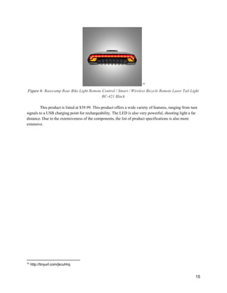
There are existing products in the market that have similar functions as the proposed design. 
There are headlights and tail lights that operate using batteries that require replacement and do not have 
energy­generating components. There is also a patent for a product that uses an accelerometer to detect if 
the bicycle is slowing down, but it also does not rely on energy­generating components. 
 
1.2.4 ­ ​Research Conclusions 
 
2
  "Traffic Safety Facts." ​Http://www­nrd.nhtsa.dot.gov​. Apr. 2014. Web.  
 
3
  Larson, C. (2011, March 21). Survey Result: Bike Light Use Good, But Not Good Enough. Retrieved 
March 19, 2016, from https://btaoregon.org/2011/03/survey­result­bike­light­use­good­but­not­good­enough/  
 
4
 ​Isaksson­Hellman, I., & Werneke, J. (2016). Detailed description of bicycle and passenger car collisions 
based on insurance claims. ​Safety Science​. 
 
5
 ​Williams, T. (2015). ​Investigating characteristics in a spatial context that contribute to where bicycle 
accidents occur​ (Doctoral dissertation, Lincoln University). 
 
6 
Research has proven that bicycle related accidents are clearly a problem. These accidents are 
largely caused by cyclist visibility issues or confusion about a cyclist’s movements. Therefore, bicycle 
safety can be improved by providing a product that improves the bicycle’s visibility at night and notifies 
vehicles when it is slowing down. There is a viable market and need for a useful product that combines 
active lights, an indicator showing deceleration, and a self­powering generator. 


7 
2. Product Requirements 
 
2.1 ­ ​Customer Requirements 
 
Using the extensive market research, a list of specific customer requirements was created. The 
research and the safety issues that need to be addressed provide insight to the product specifications that 
would apply to the market. These explicit requirements are listed below: 
 
­ Indicate when the bicycle is slowing down 
­ Run automatically 
­ Increase visibility of bicycle 
­ Durable (long life­span) 
 
 
Along with the above requirements, several implicit requirements are also considered and shown below: 
 
­ Low­maintenance 
­ Meets federal standards for vehicle lighting (red/yellow/orange for rear lighting) 
­ Affordable (comparable to bicycle accessories) 
­ Easy installation 
 
2.2 ­ ​Product Specifications 
 
The following specifications were determined based on the requirements for the product: 
 
­ Friction Generator­ Runs automatically and low user maintenance  
­ High­Intensity Red LED­ Easily visible display to other drivers 
­ Accelerometer­ Senses when the bicycle is decelerating 
­ Microcontroller­ Commands LED to light up automatically 
­ Durable Casing­ Increases life span of the device 
 
Friction Generator (Dynamo) ­ The product will use a reliable friction generator to avoid the dependency 
on batteries. A friction generator was determined to be the optimal energy generator because it will 
constantly produce electricity while the bicycle is in motion. A solar cell was also considered, however it 
was determined that batteries would be required for night­cycling, and storing the bicycle in a garage 
would not charge the batteries. By simply relying on a dynamo for energy, the bicycle could be used 
normally and the device would be automatic without need for turning on or off. 
 
8 
 
Figure 1: Friction Generator Dynamo.  6
 
High­Intensity Red LED ­ The product will use a high­intensity red LED to indicate when the bicycle is 
slowing down. Red was chosen in part due to its high visibility in all conditions. The other reason for 
choosing a red LED is the relatively low cutoff voltage requirement to illuminate the bulb. 
 
Figure 2: Red LED.  7
 
Accelerometer ­ An accelerometer was chosen as the deceleration sensor due to its ability to detect small 
changes in acceleration. For the product, the accelerometer will provide raw input data to be filtered and 
used to determine when the bicycle is slowing down. 
 
Figure 3: Generic Accelerometer Module.  8
 
Microcontroller ­ A microcontroller will be used on the device to analyze the raw input data from the 
accelerometer and to power the output LED when the bicycle is determined to be decelerating. A 
microcontroller is preferred over a microprocessor because all the components can be integrated into a 
6
 http://ecx.images­amazon.com/images/I/31ypwTcotdL.jpg 
7
 http://uk.farnell.com/productimages/standard/en_GB/42251794.jpg 
8
 http://learn.parallax.com/sites/default/files/content/kickstart/images/Memsic2125­2.png 
 
9 
single chip. The processing for this device will not be very computationally intensive and 
microcontrollers tend to require less energy to fully operate. 
 
Durable Casing ­ The product will utilize a durable casing to contain and protect the accelerometer, 
microcontroller, and LED. The casing must be able to withstand conditions such as rain and normal use 
without failing. The friction generator will be a self­contained device connected by water­resistant wires. 
 
 
2.3 ­ ​Competitive Value Analysis 
 
2.3.1 ­ ​Essential Customer Criteria 
 
Quality: 
 
Operating Conditions: How well will the product perform when it is exposed to weather or harsh 
conditions. 
 
Value  Value Point 
Well (sustains little to no damage)  3 
Moderate (sustains minor damage, but still functions)  2 
Poor (sustains significant damage, but still functions)  1 
Not at all (doesn’t function after receiving damage)  0 
 
 
Display: The visibility of the display. 
 
Value  Value Point 
Very Well (very bright and visible)  4 
Well (bright and visible)  3 
Moderate (mildly bright and barely visible)  2 
Poor (very difficult to see)  1 
Not at all (no light displayed)  0 
 
Responsiveness of Sensor: How well the sensor will react to acceleration/deceleration. 
 
10 
 
Value  Value Point 
Well (senses any change in velocity)  3 
Moderate (senses moderate change in velocity)  2 
Poor (only senses major change in velocity)  1 
Not at all (doesn’t sense change in velocity)  0 
 
 
Convenience: 
 
User Input: How fast does the user have to pedal for sensor/LED operation. 
 
Value  Value Point 
Well (minimal user input for full functionality)  3 
Moderate (moderate user input for full functionality)  2 
Poor (considerate user input for full functionality)  1 
Not at all (no functionality from significant user input)  0 
 
 
Installation Versatility: Can easily install on all bicycles. 
 
Value  Value Point 
Well (universal will all bicycles)  3 
Moderate (requires minor modifications to install)  2 
Poor (requires significant modifications to install)  1 
Not at all (can not be installed on bicycles)  0 


Battery Maintenance: How often does the battery need to be replaced. 
 
11 
 
Value  Value Point 
Never (energy generation)  5 
Never (energy supply)  4 
Infrequently (rechargeable battery)  3 
Infrequently (replaceable battery)  2 
Often (short lifespan of battery)  1 
 
 
Cost: 
 
Price: Consumer’s cost for the product. 
 
Value  Value Point 
<$30  4 
$30 ­ $40  3 
$40 ­ $50  2 
$50 ­ $60  1 
$50<  0 
 
 
2.3.2  ­ ​Metrics for Value Analysis 
 
The value of the competitor criteria is weighted below: 
 
● Operating Conditions (2) 
● Display (3) 
● Responsiveness of Sensor (3) 
● User Input (2) 
● Installation Versatility (2) 
● Battery Maintenance (2) 
● Price (1) 
 
 
12 
Each given criterion needed to be weighted depending on its significance to the customer. The 
most essential criterion is the responsiveness of the sensor. If the device can not properly measure the 
acceleration of the bicycle, the cyclist’s safety is at risk. The visibility of the display is also crucial 
towards the functionality of the device. Other vehicles and cyclists need to be able to easily see the LED 
when the bicycle is slowing down for the device to be effective. The chosen rating for display is a 3. 
Durability is very important and is rated a 3. The lifespan of the device is important, and for it to last, it 
needs to be able to withstand harsh conditions. The user input is important because the user should not 
have to be moving especially quickly for the device to still function. This value was rated a 2. The battery 
maintenance is influential because the customer does not have to worry about replacing the battery for the 
product to continue to function. This value was rated a 2. Installation versatility was next due to its 
importance for the convenience of the customer. It is not as crucial because installation is a one­time 
process and it does not affect the functionality of the device. It was rated a 2. Price was rated last as a 1. 
The device can be more expensive because it offers a premium solution that cyclists need to improve their 
safety on the streets.  
 
2.3.3 ­ ​Competitors 
 
Market research has shown that there are a variety of current products that offer similar functions 
to our design. There are many tail lights for the sole purpose of notifying other vehicles of the cyclist’s 
presence. There are headlights to improve the cyclist’s frontal vision. Lastly, there is a similar product 
that senses the bicycle’s deceleration. These products can be compared in similar markets because they all 
improve the safety of the cyclist. The chosen design is unique from its predecessors due to its 
consolidation of features and energy generation component. 
 
Tail Lights: 
 
Tail lights are lights that attach to the rear of the bicycle and light up to improve visibility 
of the bicycle to others nearby. These lights typically have one function and operate constantly. 
Some lights are constantly illuminated, and some constantly flash on and off. They all rely on 
batteries for operation, which need to be replaced or recharged. 
These products vary in price from about $10 to about $50 depending on the features that 
they offer. The distance that the light can be seen from has a large impact on the price of the 
product. Extra features like turn signals, or having a rechargeable battery are also influential on 
the final price of the product. Illustrated below are two top products on both ends of the pricing 
spectrum: 
 
 
13 
 9
Figure 4: ​Rear Bike Light Bicycle Laser Beam Rear Tail Light 
 
This product is listed at $9.99. This product offers the basic features that a tail light demands, 
including a flashing light option and a high visibility light. It requires replaceable batteries that are not 
included. 
 
 
Figure 5: Rear Bike Light Specifications 
9
 http://tinyurl.com/h65poyv 
 
 
14 
 10
Figure 6: ​Basecamp Rear Bike Light Remote Control / Smart / Wireless Bicycle Remote Laser Tail Light 
BC­421 Black 
 
This product is listed at $39.99. This product offers a wide variety of features, ranging from turn 
signals to a USB charging point for rechargeability. The LED is also very powerful, shooting light a far 
distance. Due to the extensiveness of the components, the list of product specifications is also more 
extensive. 


10
 http://tinyurl.com/jkcuhhq 
 
15 
 
Figure 7: Rear Bike Light Specifications (2) 
Headlights: 
 
Headlights are designed to shine a bright light in front of the bicycle to improve the 
cyclists frontal vision. They typically shine a constant light forwards, illuminating a certain 
distance in front of the bicycle. These products are typically consistent in the features that they 
offer, and are about the same price. Similar to tail lights, headlights also rely on batteries for 
operation.  
Headlights usually cost about $10 ­ $20 with a few premium options around $40. The 
illumination strength of the lights are the largest contributing factor towards an increase in market 
price. Two popular options are depicted below: 


16 
 11
 
Figure 8: ​Front Bike Light 5­LED Black Bicycle Headlight with Batteries Set 
 
This product offers the bare minimum features for a headlight. It is listed at only $6.99. It has the sole 
purpose of shining a light forwards to improve the cyclist’s vision. The specifications are shown below: 


Figure 9: Front Bike Light Specifications 


11
 http://tinyurl.com/hn7pfmx 
 
17 
 12
Figure 10: Front Bike Light,LS097 8400Lm 5 Mode 6 x CREE XM­L T6 LED Bike Bicycle HeadLight 
HeadLamp Kit 
 
This product also has very simplistic features, but it displays a very powerful light. It a premium 
product, so it is listed at $47.49. It is targeted at high­level cyclists who demand the highest­quality 
product on the market. 


12
 http://tinyurl.com/j33k52p 
 
18 
Figure 11: Front Bike Light Specifications (2) 
 
Brakeless Deceleration Indicator: 
 
There is one prominent product on the market with this specialization. This product uses 
an accelerometer to detect if the motorcyclist is braking, and indicate others nearby via a flashing 
light. This product is very similar to the chosen design in the features that it offers, but it operates 
slightly differently and is targeting a different market. This product also relies on batteries instead 
of energy generation. This product is displayed below: 


19 
 13


Figure 12: Brakeless Deceleration Indicator 
 
This product is listed at $129.95, demonstrating its superiority to the previously mentioned 
products in the bicycle safety market.  
 
 
2.3.4 ­ ​Value Analysis 
Table 1. Competitive Value Analysis 
 
The value analysis demonstrates that the chosen design is the most valuable product compared to 
the market competitors based on the chosen criteria. Comparing market competitors was beneficial in 
order to properly understand features that customer’s demand in the market, and how well companies 
deliver those features in their products. The brakeless deceleration indicator (44) is easily the top 
13
 http://vololights.com/products/vololights­enhanced­motorcycle­visibility/#shopify­product­reviews 
 
20 
competitor for the chosen design (46) due to its similar functionalities and features that it offers. 
However, the chosen design’s energy generating components give it the slight edge in the market. 
Any sensitivities in the value analysis likely stem from the chosen criteria and the interpreted 
weighting values. The customer’s needs were predicted without certainty because the chosen design has 
yet to be introduced to the market. 


21 
3. Design Approach 
 
3.1 ­ ​System Architecture 
 
3.1.1 ­ ​Design Overview 
 
 
Figure 13: Top Level Diagram  
3.1.2 ­ ​Modular Overview 
 
3.1.2.1 ­​ Power Generation   
Power needs to be supplied to meet the energy needs of the various components. The 
energy from the rotation of the wheels of the bicycle can be harnessed to power the system. 
 
 
22 
 
Implementation  Mountable dynamo generator 
Input  Wheel rotation 
Output  Average 3W at 6V (AC). Depends on speed of bicycle 
Table 2: Power Generation 
A reliable friction generator supplies AC power to the entire system and removes the 
dependency on batteries. The dynamo constantly and autonomously produces energy while the 
bicycle is in motion.  
 
3.1.2.2 ­ ​AC/DC Conversion  
The power produced by the dynamo is output in AC, but DC power at the proper voltage 
is required to power the microcontroller. The AC to DC converter converts the generated power 
into a usable form. 
Implementation  Bridge Rectifier, Smoothing Capacitor, Voltage Regulator 
Input  Average 3W at 6V (AC) 
Output  3.3V (DC),  maximum 800mA 
Table 3: AC/DC Conversion 
A bridge rectifier, smoothing capacitor, and a voltage regulator are all essential 
components to convert to and maintain the desired voltage.  
 
3.1.2.3 ­ ​Digital Control  
The converted DC power is used to operate the control system for the design. The logic 
system senses change in acceleration and provides commands for the device’s output. This 
module is required for the device to accurately perform its main purpose which is to indicate 
when the bicycle is decelerating. 
Implementation  Microcontroller and Accelerometer 
Input  3.3V DC 
Output  3V DC 
Table 4: Digital Control 
 
23 
The accelerometer will detect changes in velocity of the bicycle and notify the 
microcontroller. The programmed microcontroller can then send commands to the indicator 
output. 
 
3.1.2.4 ­ ​Indicator Output 
The indicator output will notify others nearby of the cyclist’s deceleration. The bright 
display is prominent and easily visible, ensuring the effectiveness of the device. 
Implementation  Bright Red LED Array 
Input  Max: V​in​=2.4V, i​in​=100mA 
Output  LEDs light up or flash depending on microcontroller commands 
Table 5: Indicator Output 
The LED array will receive power and light up accordingly based on the commands from 
the microcontroller. A transistor will receive the signal from the microcontroller and operate as a 
switch. A resistor will be used to drop the voltage down to below the maximum operating 
voltage. 
 
3.2 ­ ​Module Definition 
 
3.2.1 ­​ Power Generation Module 
3.2.1.1 ­ ​Description of Functions 
This module will generate AC power by harnessing energy from the bicycle wheel 
rotation. The fundamental component for this module is a bicycle dynamo. A dynamo is an 
electrostatic friction generator. It operates by using manual power (bicycle pedaling) to generate 
charge. The dynamo provides a constant supply of clean energy, adding a factor of convenience 
for the user.  


24 
The following schematic illustrates the dynamo’s functional components:  
   14
Figure 14: Schematic of Dynamo 
 
3.2.1.2 ­ ​Module Input 
The only input required for this module is from the user. The user manually pedals the 
bicycle, which causes the bicycle wheels to rotate. The wheel rotation energy is then harnessed by 
this module. 
 
3.2.1.3 ­ ​Module Output 
AC power will be output to the entire system when the cyclist is moving. The AC output 
parameters will vary, depending on the user’s velocity. These technical parameters can be found 
below:  


14
 http://www.seeedstudio.com/wiki/Bicycle_Dynamo_With_Bracket_­_6V_3W 
 
25 
Constant­Resistance Load Testing (18 ohms) 
Speed(km/h) 15
Output Power (W)  Output Voltage (V)  Output Current (A) 
5  0.45  2.45  0.115 
15  1.89  5.78  0.325 
30  3.21  7.23  0.435 
Table 6: Dynamo Specifications 
Table 6 demonstrates that as the speed of the bicycle increases, the output power, voltage, 
and current increase. The following graph displays the relationship between the cyclist’s speed 
and the power output from the dynamo.  
 
Figure 15: Speed vs. Output Power Graph 
Figure 15 illustrates that the output power increases at approximately an exponential rate 
as the cyclist’s speed increases. The exponential dotted trendline closely follows the speed vs. 
output power curve, which further supports this claim. 
 
As the dynamo produces electrical energy, heat energy is produced as well. The heat 
output should be considered when testing. The following table exhibits possible temperatures of 
the dynamo during operation: 
15
 http://www.seeedstudio.com/wiki/Bicycle_Dynamo_With_Bracket_­_6V_3W 
 
26 
Temperature Test: 
Surroundings temp.  Shell temp.  Temp. rise 
20℃ 16
55.2℃  32.2℃ 
Table 7: Dynamo Temperature Test 
The dynamo supplies more than enough power to meet the demand of the rest system 
even when the cyclist is moving at a slow pace. At optimal performance, the dynamo will output 
3W at 6V.  However, if the cyclist is moving quickly, the output voltage is excessive, and needs 
to be regulated. This regulation will be discussed later in the report. 
The output is also supplied in AC, which needs to be converted to DC to be used by the 
other components.This conversion process will be examined in the next module. 
 
3.2.2 ­ ​AC/DC Conversion Module 
3.2.2.1 ­ ​Description of Functions 
The AC/DC Conversion module will take the power from the dynamo generator and 
convert it to a form that can be used to power the other modules. Three components are used in 
this module. The first component is the converter. It consists of 4 diodes arranged to form a 
bridge rectifier, converting the input alternating current (AC) to direct current (DC). The 
converted DC power is often pulsed as a wave, which can lead to resistive losses. However, to 
minimize these losses, a 1000μF capacitor is then used to smooth the wave and provide a low 
impedance path for the output. Lastly, a 3.3V linear regulator is included in the process to 
normalize the voltage to 3.3V, reaching the desired voltage for the remaining components.  
A schematic was created to illustrate the AC to DC conversion process and the 
integration between each of the components. This schematic is depicted below: 
16
 http://www.seeedstudio.com/wiki/Bicycle_Dynamo_With_Bracket_­_6V_3W 
 
27 
 
Figure 16: Schematic of the AC/DC Conversion Module. 
The bridge rectifier is composed of 4 diodes. It splits the components of the AC sine 
wave and recombines them as a full wave rectification. The capacitor is added between the line 
voltage and the ground voltage to minimize the voltage ripple. The regulator takes in the line 
voltage and the common ground and outputs a regulated voltage of 3.3V by automatically varying 
the internal resistance.  
The technical specifications for the voltage regulator can be found below in the following 
table: 
 17
Table 8: Specifications of the Voltage Regulator. 
 
17
 https://www.sparkfun.com/datasheets/Components/LD1117V33.pdf 
 
28 
3.2.2.2 ­ ​Module Input 
The input to the AC/DC Conversion module is the AC output of the dynamo. This input 
will be variable and heavily influenced by the speed of motion of the bicycle. The ranges are 
documented above in Table 6. The maximum input voltage the system can handle was determined 
to be 15V, which far exceeds the potential output achievable by the dynamo generator with an 
average cyclist powering the device. Under normal operating conditions, the dynamo is expected 
to produce between 2­8V, which is supported by the proposed conversion module. 
3.2.2.3 ­ ​Module Output 
After the completion of the conversion process, this module will output a constant 3.3V. 
The output current will vary depending on the speed of the bicycle, peaking at  800mA. The 
output voltage is only predicted to drop lower than 3.3V if the bicycle is moving at speeds around 
or lower than 5 km/h, which is impractically slow for cycling. If the input voltage is lower than 
1.1V, the output will drop to 0V. If the dynamo is operating at optimum levels, the AC/DC 
Conversion module will output 3.3V and up to 800mA. The modified output will be utilized to 
power the rest of the system. 
 
3.2.3 ­ ​Digital Control Module 
3.2.3.1 ­ ​Descriptions of Functions 
The purpose of the Digital Control module is to read in the acceleration of the bicycle 
using the MMA8451 accelerometer and to determine when to activate the Indication Output 
module using digital logic in the MSP430G2553 microcontroller. When a 3.3V input is provided 
to power the control module, the accelerometer will begin to record the acceleration of the bicycle 
and provide the data to the microcontroller. If there is any backwards acceleration sensed by the 
accelerometer, the microcontroller will execute code that will direct the output module to activate 
and light the LED array. When needed, the microcontroller will output 3V DC to the LED array. 
The schematic below illustrates the pins that connect the microcontroller, accelerometer, and 
LED array, and how they are integrated with each other. 
 
29 
 
Figure 17: Schematic of Digital Control Module 
3.2.3.2 ­ ​Module Input 
The microcontroller and the accelerometer will share an input voltage (V​CC​) of 3.3V DC. 
The 3.3V is expected to be a constant value as it is coming from the output of the voltage 
regulator, and may only drop in voltage if the bicycle is traveling at extremely slow speeds of less 
than 5 km/h. The typical current supply to the control module is 330 μA, offering a power draw 
of only 1.1 mW. 
While the program is running, the microcontroller will be expecting 8 bit char data values 
from the accelerometer at a rate of 1 sample/ms. The accelerometer uses its own built­in analog to 
digital converter, and therefore the values from the accelerometer can be immediately read by the 
microcontroller. A sample rate of 1 sample/ms should be sufficient to sense any deceleration and 
to resultantly light up the LED array. 
3.2.3.3 ­ ​Module Output 
The output of the digital control module will be an active high voltage of 3V to the LED 
array when the accelerometer detects a backwards acceleration. The data rate of the output will be 
the same as the sample rate of the accelerometer, which is 1 sample/ms. The code implemented in 
the microcontroller will entirely control the output of the module. 
 
3.2.4 ­ ​Indicator Output Module 
3.2.4.1 ­ ​Description of Functions 
The purpose of the Indicator Output module is to produce a noticeable visual display 
when a signal is received from the digital control module. When a signal is received to the NPN 
transistor, the supply voltage V​in​ will flow through and into the resistor. Given that V​in​ is 3.3V, 
and the absolute maximum characteristics for the LEDs are 2.4V with 20mA, the resistor R1 will 
 
30 
have a value of at least 9Ω to avoid exceeding the absolute maximum voltage. The value of R1 
will be tested along with the LED array, starting at a value of at least 10Ω. 
The schematic for the LED Output Array is depicted below: 
 
 
Figure 18: Schematic of Indicator Output Module 
3.2.4.2 ­ ​Module Inputs 
The inputs to the Indicator Output module are the common ground, the positive voltage 
rail, V​cc​/V​in ​, and the signal in from the logic system. The common ground is assumed to be 0V. 
The positive voltage rail will be 3.3V at optimal operating conditions. This value may decrease 
slightly when the bicycle is moving at a very low velocity. The signal from the microcontroller 
will be V​cc​­0.3V for all values of V​cc​. This module will draw 100mA from the V​cc​ and will 
dissipate .33W of energy. 
3.2.4.3 ­ ​Module Outputs 
The output of the Indicator Output module is a red light emitted by the 5 high­intensity 
red LEDs. The output will be activated by a signal from the logic system. The .33W will be 
dissipated. 
 
3.2.5 ­ ​System Integration 
Each module will be tested individually to ensure that each module functions properly separately 
before integrating them together into the entire system. The hardware modules that must be tested are the 
 
31 
Power Generation module and the AC/DC module. The software of the Digital Control and Output 
module must also be programmed and tested before they are integrated with their hardware counterparts. 
3.2.5.1 ­ ​Power Generation 
The dynamo generator will be attached to a bicycle wheel and have its output AC 
voltages monitored at various speeds on the bicycle. The dynamo must be able to output 6V and 
1.89W at an average speed of 15 km/h. The generator’s voltage output should only drop below an 
operational level of 3.3V when the bicycle is traveling at a much slower speed of 5 km/h. These 
values will ensure that when the generator is connected to the AC/DC converter, and the system 
as a whole, it will provide enough power to operate the microcontroller, and output to the LED. 
3.2.5.2 ­ ​AC/DC Conversion 
Once the AC/DC conversion module circuit is constructed, the module will be connected 
to an AC voltage source and a load resistance of 50Ω. The AC voltage input will be varied and 
tested between the minimum value of 3.3V and the maximum value of 8V. The output voltage of 
the regulator is expected to be 3.3V at all values of input voltage, showing how it will perform 
when connected to the dynamo input generator. 
3.2.5.3 ­ ​Indicator Output 
The LED array will be tested by itself before it is integrated with the microcontroller. The 
LEDs are expected to receive an input of 2.4V from the microcontroller pin. The actual output 
voltage of the microcontroller is expected to be 3V, so it will be regulated down to 2.4V using a 
resistor with at least 10Ω (as calculated in section 3.4). To test the LED array configuration 
independently, the module will be connected to a 3.3V power source to see if the LEDs light up. 
3.2.5.4 ­ ​Digital Control 
To test the Digital Control module, the MMA8451 accelerometer will be connected to the 
MSP430G2553 microcontroller via pins 1.6 and 1.7. Both the microcontroller and the 
accelerometer will be powered by a 3.3V DC voltage for use in testing. The output LED array 
will also be connected to the microcontroller via pin 1.2. Code will be written in Code Composer 
Studio that will read the data input from the accelerometer, notice when there is a prolonged 
negative acceleration, and trigger the illumination of the output LEDs. This module will be 
initially tested by using variables in the code to simulate negative acceleration. When the code is 
complete and operational, the full module will be tested by connecting it to a 3.3V power source, 
and actually simulating a negative voltage with motion of the module in order to light the LEDs. 
3.2.5.5 ­ ​Full System Integration 
After successful testing of every individual module, the full system will be prototyped 
following the circuit diagrams that have been shown earlier in the report. The dynamo generator 
will be directly attached to the front wheel of the bicycle. The rest of the components will be 
wired together on a protoboard for initial testing. The board will be attached to the back of the 
bicycle and oriented in the correct direction in order to detect backwards motion. The final device 
 
32 
will be enclosed in durable casing and wiring, and the modules will be soldered together to create 
a more permanent product. 
3.2.5.6 ­ ​System Testing 
Once all the modules have been integrated together, and the prototype is mounted on the 
bicycle, the system will be tested by riding the bicycle at varying speeds to observe the effect on 
the LED. If every module is working together correctly, then the LED should function when 
decelerating from all speeds over 5 km/h. If something is not working as expected, then each 
module will be reanalyzed individually to detect issue and develop a solution. 


33 
4. Product Testing 
 
4.1 ­ ​Product Functionality 
 
The product is 100% functional, fulfilling all tested criteria. Each of the product’s 
features are functional. The product successfully harnessed energy from the rotation of the tires, 
sensed deceleration of the bicycle, and provided the desired LED output. The input ranges of 
each module properly met the predicted specifications. The output devices for each module also 
performed fully functionally, also meeting the predicted specifications. Lastly, the power 
requirements, provided by the dynamo, comfortably met the specifications demanded by the 
system in order to function optimally. 
 
4.2 ­ ​System Testing & Results 
 
The system testing was broken down by module to ensure proper functionality before integration. 
After each module was tested and performed as expected, the product could be assembled and tested as 
one unit. 
 
 
4.2.1 ­ ​Power Generation Module Testing 
 
The power generation module has performed as expected thus far through testing. The dynamo 
was tested by manually spinning the generator by hand at a constant rate. The AC output was recorded in 
the lab with an oscilloscope at a constant frequency, and at about 6V, exactly as anticipated. The lab 
testing was a success, and the module was ready to be integrated with the other modules on the bicycle. 
 
 
4.2.2 ­ ​AC/DC Conversion Module Testing 
 
The AC/DC conversion module has also performed as expected through testing. The components 
were mounted on a breadboard according to the designed schematic and were tested in the lab. A picture 
of module is depicted below: 
 
34 
 
Figure 19: AC/DC Conversion  
 
A function generator was used to input 6V AC into the module, and the output was measured 
constantly at about 3.3V DC. The multimeter reading is shown below: 
 
 
Figure 20: AC/DC Conversion Multimeter Reading 
 
The AC/DC conversion module was able to convert the input AC voltage into the desired  DC 
output, demonstrating the effectiveness of the module. 
 
35 
 
4.2.3 ­ ​Digital Control Module Testing 
 
The digital control module has performed as expected throughout the testing phase. The 
preliminary code commands the onboard LED to light up when desired. However, the most difficult 
aspect of this module has been integrating the accelerometer with the microcontroller using the I​2​
C data 
transfer protocol. Once the two components were successfully integrated, however, the coding was 
straightforward.  
The module was mounted on a breadboard, and connected to a power supply as the input. When 
the module is at rest, the accelerometer does not detect any acceleration in the specified Y­direction, and 
the onboard LED is constantly lit. When the module is tilted in the correct direction, the accelerometer 
detects the downward acceleration due to gravity on the its Y­axis, and the onboard LED flashes at a 
constant rate. This module is displayed below: 
 
 
Figure 21: Digital Control Module Testing 
 
The illuminated onboard LED portrays that the system is at rest. These results occurred exactly as 
anticipated, demonstrating the success of the module. The module can be used to combine the AC/DC 
conversion module and indicator output module.  
 
 
4.2.4 ­ ​Indicator Output Module Testing 
 
The indicator output module has performed even better than predicted. On a breadboard, the 
LEDs were mounted in parallel with one another, and with a resistor in series. A 100Ω resistor was 
initially used as a precaution to avoid overloading the LEDs, and to protect the eye’s of the testers. 3.3V 
was supplied from a DC power supply as the module’s input, causing the LEDs to faintly light up. 
However, the success of the design demands a very bright and noticeable output. The resistor in series 
 
36 
was modified, and replaced with a 10Ω resistor. The observed LED output was as bright as desired. This 
module in effect can be seen below: 
 
 
Figure 22: LED Output 
 
The minor resistor adjustment permitted the LED output to fulfill the product requirement. This 
module has performed optimally in the lab and has proven to be effective on its own. 
 
 
4.2.5 ­ ​Integrated System Testing 
 
After each module was working individually, they were integrated together for testing. The 
AC/DC conversion module was integrated with the indicator output module by connecting the circuits. 
The joint module was tested with a power supply, and the result was successful. Next, the digital control 
module was connected to the joint module, creating a three­module system. This system was connected to 
a power supply for testing. The LEDs output a constant bright light when the system is at rest. However, 
when the accelerometer is moved, the output LEDs flash. The module is shown below: 
 
 
37 
  
Figure 23: Three­Module System Test 
 
This three­module system tested successfully, and it was time to integrate it with the power 
generation module on the bicycle. However, before mounting the three­module system onto the bicycle, it 
needed to be installed onto one breadboard for portability and convenience. This three module system is 
shown functioning below:  
 
 
Figure 24: Three Module System on Single Breadboard 
 
 
38 
This single breadboard system worked properly, and was ready to mount onto the bicycle. In 
order to mount the system, casing was needed to protect and secure the components while the bicycle is in 
motion. The breadboard and microcontroller were attached to durable cardboard with duct tape, 
stabilizing the system. Next, the unit was attached to the rear of the bicycle below the seat, so that the 
indicator lights could be clearly visible to others behind the bicycle. Finally, the power generation 
module(the dynamo) was fastened to the rear tire with metal brackets and bolts, and then connected to the 
breadboard system with a wire. The entire system was now installed on the bicycle and ready for testing. 
The mounted system on the bicycle can be seen below: 
 
 
Figure 25: Mounted System on Bicycle 
 
The product was initially tested by manually spinning the wheel to determine if the dynamo 
output was performing as planned. The friction from the tire caused the friction generator to rotate, which 
in turn caused the LEDs to light up brightly. The bicycle was then brought outside for further testing in a 
 
39 
realistic environment, the street. The bicycle was ridden by a team member to continue testing. Riding at 
a slow rate still caused the LEDs to illuminate brightly, and as the speed increased, the brightness further 
increased.  
Next, the deceleration indicator needed to be tested. The bicycle was slowed using the hand 
brakes to observe for deceleration. The LEDs flashed a few times as the bicycle was brought to rest from 
a reasonable speed, operating exactly as hoped. This result was photographed and is displayed below: 
 
 
Figure 26: Bicycle Test Run 
The photo shows the LEDs constantly lit up as the bicycle moves. The indicator LEDs were 
noticeable and prominent from a distance, and will definitely improve the safety of the cyclist.  


40 
5. Cost Analysis 
 
5.1 ­ ​Initial Investment 
 
The initial component cost to develop the product prototype was $36.98. However, as 
components are bought in large quantities directly from the manufacturer, this cost is reduced to about $8. 
This significant price drop stems from the substitution of  the microcontroller and accelerometer with 
small chips of negligible value. This $8 price does not include manufacturing costs or other fixed/variable 
costs. A total initial investment of $5,000 was estimated to include initial startup costs. 
 
5.2 ­ ​Return on Investment (ROI) 
 
Market research determined that the prospective market size for the product is about 500,000. 
From this statistic, about 5% of the market was conservatively assumed to purchase this product within 
the first year of its release, resulting in the sale of about 2,500 units. The product’s selling price is 
competitively listed at $40, which would result in a weekly revenue of  $1,900. After totaling the annual 
total revenue and costs, the annual return of investment could be calculated at 174%. A graph of this 
analysis is provided below:  
 
 
Figure 27: ROI Analysis 
 
The intersection of the revenue and cost projects demonstrates that the breakeven point will be 
reached by week 5, leading to profit. The total projected revenue after one year is $1.6 million.  
This cost analysis explains how this product is a worthwhile investment. With a reasonable initial 
investment and a significant rate of return, this product is expected to be very successful in the targeted 
market. 
 
41 
6. Failure and Hazard Analysis 
 
Failure and hazard analysis was conducted to determine potential threats that can arise in the 
system. The analysis is divided into threats that can occur internally, a result of system failure, and threats 
that can occur externally, a result of outside influence on the system. 
 
6.1 ­ ​Internal Threats 
 
The system is not at risk of any major hazards or failures from internal causes. The circuitry 
operates at the specified voltages, and the inputs/outputs for each module performs exactly as theorized. 
The internal system should operate normally unless external hazards are presented.  
 
 
6.2 ­ ​External Threats 
 
There are a few external threats to the system that can lead to potential failures in operation. Since 
the device is mounted to a bicycle, it can be damaged by external factors such as physical impact or 
unideal weather conditions. If the bicycle is affected by external factors, the circuitry can be damaged, 
and the device can even be dismounted from the bicycle. 
To help combat these concerns, the wires and components are safely secured to the bicycle to 
increase durability. Duct tape and durable cardboard were used frivolously as primary protection 
components for the device. Further improvements to the design to mitigate these concerns will be 
discussed later in the report in recommendations.   
There is also one hazard of this device that can potentially harm the user. If the bicycle sustains 
high speeds for long durations, both the dynamo and the regulator generate large amounts of excess heat. 
This heat will build up in the metal casing and heat sink at temperatures that could be hazardous to a user 
if he/she were contacted directly. In order to reduce the possibility of user harm, the following precautions 
were implemented:  
● The regulator was placed in the center of the breadboard to avoid user contact. 
● The dynamo was mounted towards the top of the rear wheel, a safe distance from the 
user. 


42 
7. Recommendations 
 
In order to continue to improve the effectiveness of this product, and to reduce the areas of 
concern, a few additional steps should be taken. 
The modules should be transferred from a breadboard to a more permanent printed circuit board 
(PCB). This change would improve the reliability of the device and secure the components more 
definitively. A PCB would also improve the convenience of installation for the user. 
The system should be enclosed in a more durable casing to protect the components and improve 
the reliability of the device. The system will be protected from external threats such as harsh weather 
conditions or physical damage.  
The digital control programming should be expanded to compensate for the directional angle of 
the accelerometer. Added coding would include recalibration of the accelerometer either on startup, or 
periodically to ensure the accuracy of the direction of acceleration. This would improve the 
responsiveness of the indicator output, providing a more reliable deceleration output for the user. Also, 
more logic can be included in the coding to make the sensor more or less sensitive, depending on what 
would improve the device after further testing. 
 The number of LEDs in the array should be increased, and their configuration should be 
reevaluated to further improve upon the cyclist’s visibility. When actually manufacturing the product for 
sale, higher quality LEDs can be used that are more effective. 


43 
8. Conclusions 
 
The goal of this course design challenge was to develop a useful product that harvests stray 
energy from the environment, senses some parameter within that environment, and provides some level of 
safety to the user. The bicycle deceleration indicator device is believed to have satisfied each of these 
criterion. The device harvests stray energy from the rotation of the tires, senses the deceleration of the 
bicycle, and improves the safety of the cyclist by increasing his/her visibility to others on the road. This 
product is expected to be successful in the targeted market, and was developed in a cost­effective manner.   
Throughout the design process, the following team oriented goals were accomplished: 
1. The engineering design process was utilized. 
2. The product was tailored to the targeted market’s needs. 
3. The product’s successes and failures were evaluated, leading to several lessons learned. 
4. The final product created can be taken pride in. 
 
The designed product presents a solution to a realistic problem, and is believed to be thoroughly 
successful. The development of this product was worthwhile, and the lessons learned can be used in many 
future applications. 


44 
Appendix A: Parts List 
 
Qty  Part No.  Reference  Description  Distributor  Unit ($)  Subtotal ($) 
1  COM­00526  REG  3.3V linear regulator  Sparkfun  1.9500  1.95 
1  COM­08982  C1 
1000μF Electrolytic Decoupling 
Capacitor  Sparkfun  0.3500  0.35 
1  COM­13689  T1  Transistor ­ NPN (BC337)  Sparkfun  0.5000  0.50 
4  COM­08589  D1­4  Diode Rectifier  Sparkfun  0.1500  0.60 
5  COM­00528  LED1­5  LED ­ Super Bright Red  Sparkfun  0.9500  4.75 
1  485­2019  ACCEL 
Adafruit MMA8451 3­Axis 
Accelerometer  Mauser  7.9500  7.95 
1 
595­MSP­exp
430G2  MC 
TI MSP­EXP430G2 Launchpad Dev 
Kit  Mauser  9.9900  9.99 
1  POW31944M  Dynamo  Motorized Power Generator 6V 3W  ebay  15.89  15.89 
Table 9: Parts List 


45 
Appendix B: Computer Code 


46 


47 
 
Figure 28: Digital Control Code 
 
48 

FinalReportHW6