Download as PPSX, PPTX
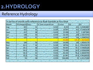
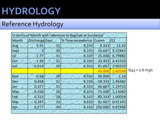
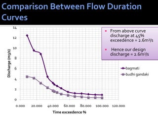
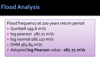

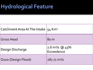
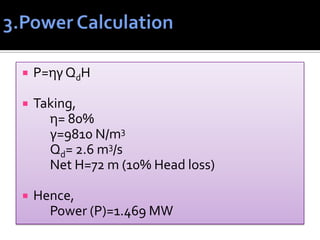
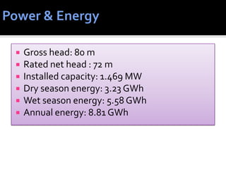


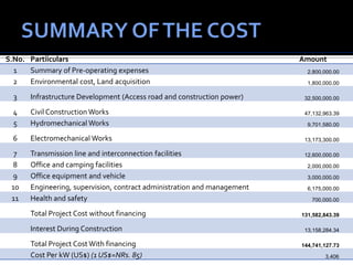
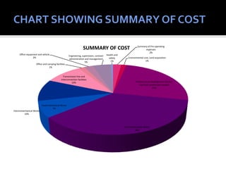
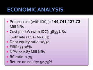


The document presents the design of a 1.469 MW run-of-river hydropower project on Chhote Khola in Gorkha District, Nepal. Key aspects of the design include a gross head of 80 m, design discharge of 2.6 m3/s, and installed capacity of 1.469 MW. The proposed project involves civil structures such as an intake, penstock, powerhouse, and tailrace. A cost estimate puts the total project cost at NRs. 144.74 million. An economic analysis yields a FIRR of 33.76% and NPV of NRs. 112.87 million.


