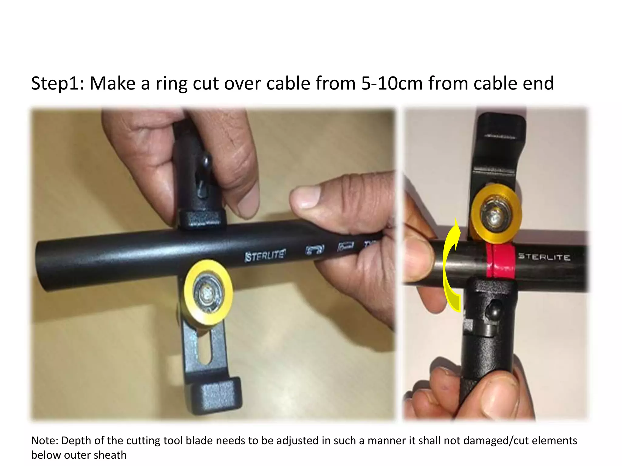
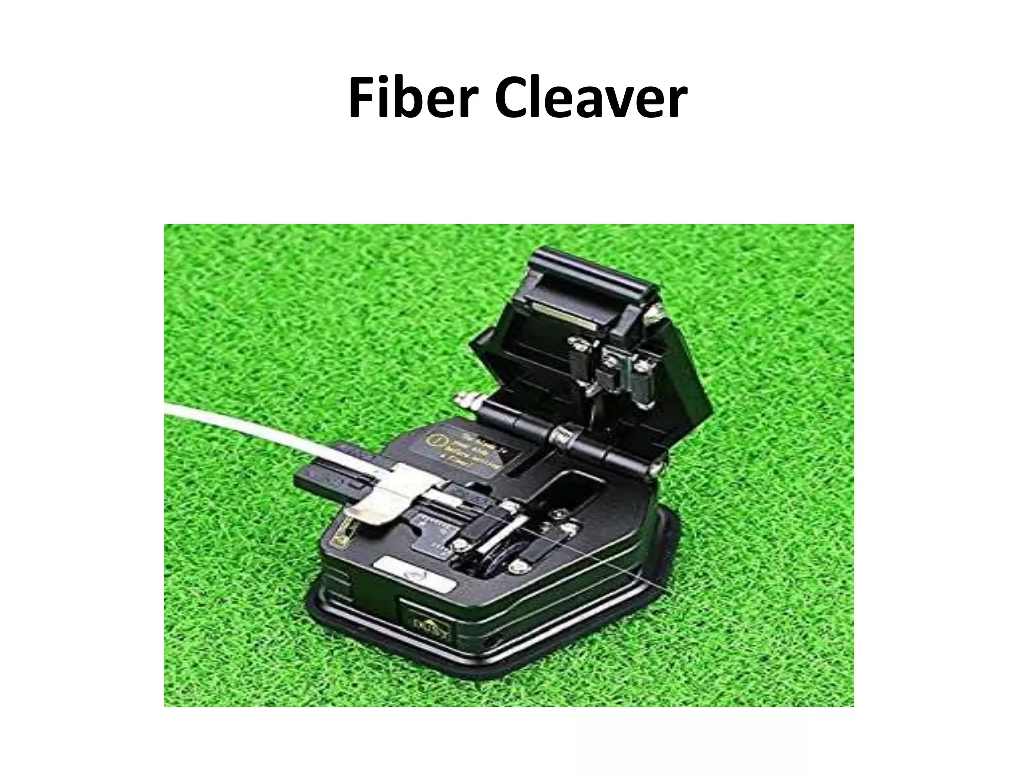
FIBER OPTICS NETWORK DESIGN
AGENDA
•Optical Fiber cable splicing techniques.
• OF indicators.
• OF connectors.
• OF cable terminations.
• OF network trouble shooting.
OFC splicing
Splicing Methods
The following three types are widely used:
1. Mechanical or V- groove splicing.
2. Adhesive bonding or Glue splicing.
3. Fusion splicing.
• Fusion splicing method is widely using.
Cable End Preparation
ACS Tool
ACS Tool used for Mid-
Span
• The Miller ACS (Armored Cable Slitter) tool as shown
below is recommended by Sterlite to remove the outer
jacket, armoring, and inner jacket for cable end
preparation.
•The sheath should be
removed in layers: first
the outer jacket, then
the and then the inner
jacket with centre tube
Cable End Preparation for
Splicing/Termination
Step1: Make a ring cut over cable from 5-10cm from cable end
Note: Depth of the cutting tool blade needs to be adjusted in such a manner it shall not damaged/cut elements
below outer sheath
Cable End Preparation for
Splicing/Termination
Step2: Slightly bend, squeeze and pull the end 5-10cm so that we
can able to see the elements below cable sheath
Cable End Preparation for
Splicing/Termination
Step3: Take out the rip cord thread
(2 nos. of twisted red & white coloured thread)
Cable End Preparation for
Splicing/Termination
Step4: Pull out both the rip cords along the cable length required for
splicing (0.75 to 1.5m) and cut outer jacket
Cable End Preparation for
Splicing/Termination
Step5: Now we will remain with stranded core. Identify unwanted
elements like binder thread,dummy fillers and cut them.
Cable End Preparation for
Splicing/Termination
Step6: Now we will remain with 8 nos. Of loose tube in outer layer
and centre tube . Make a ring cut over centre black tube which will
separate both outer black sheath.
Note: Depth of the cutting tool blade needs to be adjusted in such a manner it shall not
damaged/cut ribbon fiber.
Cable End Preparation for
Splicing/Termination
Step7: Mark a cut over all loose tubes in sensory layer and take out
PBT covering and clean a fibre in all tubes
Note: Ensure no damage to the fibre at the time making cut on
OFC cable cutter
SCISSORS
LOOSE TUBE CUTTER
Fiber Stripper
Fiber Cleaver
Fiber Cleaver
(i) Broken ends.
(ii) Ripped ends.
(iii) Slanting cuts.
(iv) Unclean ends
Fibers should not splice with the following conditions.
The main functions of Fusion splicing machine
are:
•Auto active alignment of the core.
•Auto arc fusion.
•Video display of the entire process.
•Indication of the estimated splice loss.
Functions of Fusion Splicing machine
Fusion splicing
• Fusion
• Lowest loss
• Lowest back reflection
• Strongest
• Faster
• High capital cost
• Low per splice cost
• Generally used for OSP construction
Fusion splicing machine
Fusion splicing procedure.
•Overlapping of OF cable 1+ mtr in where splicing has to
done.
• Insert both ends into joint closure kit and fix it for preparation.
• Prepare fibers to insert into the machine.
Main functions in fusion splicing procedure are:
•Auto active alignment of the core and cladding.
•Auto arc fusion.
•Video display of the entire process.
•Indication of the estimated splice loss.
• Proof test.
Auto alignment
It is desirable to limit the
average splice loss to be
less than 0.1 dB.
JOINTING CLOSURE KIT
JOINTING TYPES
Jointing types
• Straight joint (SJC) : When ever joint execute in
between equal size cable
ex: 24 F x 24 F
•Branch joint (BJC): When ever joint execute from one
direction to different directions.
ex: 24 F x 12 F x 12 F
Indicators along route
• Route indicator
At every 200 m route length of showing name of
route & no of indicators.
• Joint indicator
At every joint (Splice) generally it is placed at
every 2/4 Km(Drum length).
.
Indicators
OF cable Joint indicator is in orange colour.
OF cable running indicator is in yellow colour.
OF connectors
• Connectors are using to connect easily at terminal
points.
•There are quite a few different styles of connectors.
Through out the globe, for networking and audio/video,
the three most popular styles are FC,LC, SC, and ST. LC
and SC tend to be the most commonly used styles.
Today, ST connectors are seeing more limited usage.
Fiber connectors.
CONNECTOR
• The connectors are re-matable interconnect
devices, which provide flexibility required in a
Fiber Optic Transmission system.
•The basic function required of connectors is to
allow transfer of optical power from one fiber
component to another with minimum loss and
possibility of disconnection and re-mating number
of times with minimum insertion loss.
Connector Requirements
• The attenuation in optical fiber connectors should be
less than 1 dB.
• The connector must provide consistent performance on
each re-mating.
• The connector must provide protection to the fiber so
that it does not break while being handled.
• The connectorisation technique should be simple.
• The connector size should not be very much bigger than
the fiber size and it should not be too small.
• Connector must be cost effective.
Popular OF connectors
FC (Ferrule Connector)
• Ferrule Connector (It is a round, threaded fiber optic
connector) , designed by NTT-Japan.
• It was the first fiber optic connector to use a
ceramic ferrule.
• The FC is a screw type connector with a 2.5mm
ferrule.
• FC is becoming less common and mostly replaced
by SC and LC because of its vibration loosening and
insertion loss.
SC: Square connector / Subscriber
connector
• It was developed by Nippon Telegraph and Telephone.
• Now it has widely applied in single mode fiber optic
cable, analog CATV, GPON, GBIC. (GBIC. Short for gigabit
interface converter, a transceiver that converts serial
electric signals to serial optical signals and vice versa.).
• With the ever-increasing popularity in the market, the
manufacturing cost for SC went down.
• SC is a snap (push-pull coupling) connector with a
2.5mm ferrule diameter.
ST ( Straight Tip) Connector
• The ST connector was developed by AT&T shortly after
the arrival of the FC.
• ST uses a bayonet mount other than a screw thread.
LC: Lucent Connector
• It is a push-pull, small form factor connector that
uses a 1.25mm ferrule, half the size of the SC.
• It is ideal for high-density connections, SFP and
SFP+ transceivers and XFP( 10G SFP) transceivers.
• LC is compatible for transceivers and active
networking components, it will continue to grow in
the FTTH arena ( ONT side).
Patch cord and Pig tail
• Patch cords and pig tails are used in indoor
premises.
• Pig tail having connector on one side to the tight
tube buffer cable.
• Patch cord having connectors on both sides to
the tight tube buffer cable.
• Pig tail use in between CTB ( cable termination
box) and FDF (fiber distribution frame ).
• Patch cord use in between FDF to Transmission
system.
Different patch cords
SC-SC
SC-LC
FC-SC
Pig Tails
SC pig tail
FC pig tail
SC Adapter
SC SM PC Adapter
SC SM APC Adapter
SC SM Duplex Adapter
LC Adapter
LC SM PC Adapter
LC SM APC Adapter LC SM Duplex Adapter
FC Adapter
ST Adapter
FDF
Fiber Distribution Frame
Features of FDF
• Flexible installation, wall type or back type, and
can be installed in large groups.
• Front operations.
• Suitable for ribbon and non-ribbon optic fibers.
• Suitable for inserting installation of SC, FC, ST
(additional flange)adapters.
FDF
FDF
Transmission Network
Tx
Sys
Tx
Sys
FDF FDF
CTB/TJB
CTB/TJB
OF cable
Pig tail
Pig tail
Patch card
TROUBLE SHOOTING
Meters using with OFC network
• OTDR ( Optical time Domain Reflecto meter.
. For trace the type of fault and distance of fault.
. Signal loss of entire span / lose events.
Optical Time Domain Reflecto meter
• The OTDR Measurements.
• Locate End of Fiber (Fault Locate)
• Measure End-to-End Loss
• Locate Splices & Defects
• Measure Splice & Defect Loss
• Measure Splice & Connector Reflectance
• Calculate Optical Return Loss
60
X-Ray analysis of Fiber cable
OTDR Basic Principles
An OTDR uses the effects of
- Rayleigh Backscattered light.
-Fresnel reflection to measure the fiber's
condition, but the Fresnel reflection is tens of
thousands of times greater in power level than the
backscatter.
OTDR Basic Principle
62
OTDR working
An OTDR uses the effects of Rayleigh scattering and Fresnel reflection
to measure the fiber's condition. The timer produces a voltage pulse .
The ‘on’ time being between 1ns and 10us. Directional Coupler allows
laser to go straight to fibre and backscatter laser to APD. Internal
Memory or Disk or RS 232 used for data backup .
63
Typical OTDR display-Fresnel Reflection s
66
OTDR Loss- Connector and Splice
67
Typical OTDR trace-1
68
Fiber Fault Localization using OTDR
(Optical Time Domain Reflectometer)
Meters using with OFC network
•OPTICAL POWER METER
An optical power meter (OPM) is a device used
measure the power in an optical signal. The term
usually refers to a device for testing
average power in fiber optic systems.
Visual Fault Locator
A visual fault identifier or visual fault locator (VFI / VFL)
is a visible red laser designed to inject visible light
energy into a fiber. Sharp bends, breaks, faulty
connectors and other faults will “leak” red light
allowing technicians to visually spot the defects.
Visual fault locator
OF light used in systems is
invisible. By injecting the
visible light from a source,
such as a LED or
incandescent bulb, one can
visually trace the fiber from
transmitter to receiver to
insure correct orientation
and check continuity
besides. The simple
instruments that inject
visible light are called visual
fault locators.
72
A simplified FIBRE OPTICS TRANSMISSION
SYSTEM (FOTS) that comprises of the following sub
systems.
• Digital multiplex sub system
• Optical line transmission system
• Central supervisory system
• Alarm sub system
• Power supply sub system
• De-multiplex sub system
TRANSMISSION SYSTEM
FIBER OPTICS NETWORK DESIGN__.pptx

FIBER OPTICS NETWORK DESIGN__.pptx

  • 1.
  • 2.
    AGENDA •Optical Fiber cablesplicing techniques. • OF indicators. • OF connectors. • OF cable terminations. • OF network trouble shooting.
  • 3.
    OFC splicing Splicing Methods Thefollowing three types are widely used: 1. Mechanical or V- groove splicing. 2. Adhesive bonding or Glue splicing. 3. Fusion splicing. • Fusion splicing method is widely using.
  • 4.
  • 5.
    ACS Tool ACS Toolused for Mid- Span • The Miller ACS (Armored Cable Slitter) tool as shown below is recommended by Sterlite to remove the outer jacket, armoring, and inner jacket for cable end preparation. •The sheath should be removed in layers: first the outer jacket, then the and then the inner jacket with centre tube
  • 6.
    Cable End Preparationfor Splicing/Termination Step1: Make a ring cut over cable from 5-10cm from cable end Note: Depth of the cutting tool blade needs to be adjusted in such a manner it shall not damaged/cut elements below outer sheath
  • 7.
    Cable End Preparationfor Splicing/Termination Step2: Slightly bend, squeeze and pull the end 5-10cm so that we can able to see the elements below cable sheath
  • 8.
    Cable End Preparationfor Splicing/Termination Step3: Take out the rip cord thread (2 nos. of twisted red & white coloured thread)
  • 9.
    Cable End Preparationfor Splicing/Termination Step4: Pull out both the rip cords along the cable length required for splicing (0.75 to 1.5m) and cut outer jacket
  • 10.
    Cable End Preparationfor Splicing/Termination Step5: Now we will remain with stranded core. Identify unwanted elements like binder thread,dummy fillers and cut them.
  • 11.
    Cable End Preparationfor Splicing/Termination Step6: Now we will remain with 8 nos. Of loose tube in outer layer and centre tube . Make a ring cut over centre black tube which will separate both outer black sheath. Note: Depth of the cutting tool blade needs to be adjusted in such a manner it shall not damaged/cut ribbon fiber.
  • 12.
    Cable End Preparationfor Splicing/Termination Step7: Mark a cut over all loose tubes in sensory layer and take out PBT covering and clean a fibre in all tubes Note: Ensure no damage to the fibre at the time making cut on
  • 13.
  • 14.
  • 15.
  • 16.
  • 17.
  • 18.
  • 19.
    (i) Broken ends. (ii)Ripped ends. (iii) Slanting cuts. (iv) Unclean ends Fibers should not splice with the following conditions.
  • 23.
    The main functionsof Fusion splicing machine are: •Auto active alignment of the core. •Auto arc fusion. •Video display of the entire process. •Indication of the estimated splice loss. Functions of Fusion Splicing machine
  • 24.
    Fusion splicing • Fusion •Lowest loss • Lowest back reflection • Strongest • Faster • High capital cost • Low per splice cost • Generally used for OSP construction
  • 25.
  • 26.
    Fusion splicing procedure. •Overlappingof OF cable 1+ mtr in where splicing has to done. • Insert both ends into joint closure kit and fix it for preparation. • Prepare fibers to insert into the machine. Main functions in fusion splicing procedure are: •Auto active alignment of the core and cladding. •Auto arc fusion. •Video display of the entire process. •Indication of the estimated splice loss. • Proof test.
  • 27.
  • 31.
    It is desirableto limit the average splice loss to be less than 0.1 dB.
  • 32.
  • 33.
    JOINTING TYPES Jointing types •Straight joint (SJC) : When ever joint execute in between equal size cable ex: 24 F x 24 F •Branch joint (BJC): When ever joint execute from one direction to different directions. ex: 24 F x 12 F x 12 F
  • 34.
    Indicators along route •Route indicator At every 200 m route length of showing name of route & no of indicators. • Joint indicator At every joint (Splice) generally it is placed at every 2/4 Km(Drum length). .
  • 35.
    Indicators OF cable Jointindicator is in orange colour. OF cable running indicator is in yellow colour.
  • 36.
    OF connectors • Connectorsare using to connect easily at terminal points. •There are quite a few different styles of connectors. Through out the globe, for networking and audio/video, the three most popular styles are FC,LC, SC, and ST. LC and SC tend to be the most commonly used styles. Today, ST connectors are seeing more limited usage.
  • 37.
  • 39.
    CONNECTOR • The connectorsare re-matable interconnect devices, which provide flexibility required in a Fiber Optic Transmission system. •The basic function required of connectors is to allow transfer of optical power from one fiber component to another with minimum loss and possibility of disconnection and re-mating number of times with minimum insertion loss.
  • 40.
    Connector Requirements • Theattenuation in optical fiber connectors should be less than 1 dB. • The connector must provide consistent performance on each re-mating. • The connector must provide protection to the fiber so that it does not break while being handled. • The connectorisation technique should be simple. • The connector size should not be very much bigger than the fiber size and it should not be too small. • Connector must be cost effective.
  • 41.
  • 42.
    FC (Ferrule Connector) •Ferrule Connector (It is a round, threaded fiber optic connector) , designed by NTT-Japan. • It was the first fiber optic connector to use a ceramic ferrule. • The FC is a screw type connector with a 2.5mm ferrule. • FC is becoming less common and mostly replaced by SC and LC because of its vibration loosening and insertion loss.
  • 43.
    SC: Square connector/ Subscriber connector • It was developed by Nippon Telegraph and Telephone. • Now it has widely applied in single mode fiber optic cable, analog CATV, GPON, GBIC. (GBIC. Short for gigabit interface converter, a transceiver that converts serial electric signals to serial optical signals and vice versa.). • With the ever-increasing popularity in the market, the manufacturing cost for SC went down. • SC is a snap (push-pull coupling) connector with a 2.5mm ferrule diameter.
  • 44.
    ST ( StraightTip) Connector • The ST connector was developed by AT&T shortly after the arrival of the FC. • ST uses a bayonet mount other than a screw thread.
  • 45.
    LC: Lucent Connector •It is a push-pull, small form factor connector that uses a 1.25mm ferrule, half the size of the SC. • It is ideal for high-density connections, SFP and SFP+ transceivers and XFP( 10G SFP) transceivers. • LC is compatible for transceivers and active networking components, it will continue to grow in the FTTH arena ( ONT side).
  • 46.
    Patch cord andPig tail • Patch cords and pig tails are used in indoor premises. • Pig tail having connector on one side to the tight tube buffer cable. • Patch cord having connectors on both sides to the tight tube buffer cable. • Pig tail use in between CTB ( cable termination box) and FDF (fiber distribution frame ). • Patch cord use in between FDF to Transmission system.
  • 47.
  • 48.
    Pig Tails SC pigtail FC pig tail
  • 49.
    SC Adapter SC SMPC Adapter SC SM APC Adapter SC SM Duplex Adapter
  • 50.
    LC Adapter LC SMPC Adapter LC SM APC Adapter LC SM Duplex Adapter
  • 51.
  • 52.
  • 53.
  • 54.
    Features of FDF •Flexible installation, wall type or back type, and can be installed in large groups. • Front operations. • Suitable for ribbon and non-ribbon optic fibers. • Suitable for inserting installation of SC, FC, ST (additional flange)adapters.
  • 55.
  • 56.
  • 57.
  • 58.
  • 59.
    Meters using withOFC network • OTDR ( Optical time Domain Reflecto meter. . For trace the type of fault and distance of fault. . Signal loss of entire span / lose events.
  • 60.
    Optical Time DomainReflecto meter • The OTDR Measurements. • Locate End of Fiber (Fault Locate) • Measure End-to-End Loss • Locate Splices & Defects • Measure Splice & Defect Loss • Measure Splice & Connector Reflectance • Calculate Optical Return Loss 60 X-Ray analysis of Fiber cable
  • 61.
    OTDR Basic Principles AnOTDR uses the effects of - Rayleigh Backscattered light. -Fresnel reflection to measure the fiber's condition, but the Fresnel reflection is tens of thousands of times greater in power level than the backscatter.
  • 62.
  • 63.
    OTDR working An OTDRuses the effects of Rayleigh scattering and Fresnel reflection to measure the fiber's condition. The timer produces a voltage pulse . The ‘on’ time being between 1ns and 10us. Directional Coupler allows laser to go straight to fibre and backscatter laser to APD. Internal Memory or Disk or RS 232 used for data backup . 63
  • 66.
  • 67.
    OTDR Loss- Connectorand Splice 67
  • 68.
  • 69.
    Fiber Fault Localizationusing OTDR (Optical Time Domain Reflectometer)
  • 70.
    Meters using withOFC network •OPTICAL POWER METER An optical power meter (OPM) is a device used measure the power in an optical signal. The term usually refers to a device for testing average power in fiber optic systems.
  • 71.
    Visual Fault Locator Avisual fault identifier or visual fault locator (VFI / VFL) is a visible red laser designed to inject visible light energy into a fiber. Sharp bends, breaks, faulty connectors and other faults will “leak” red light allowing technicians to visually spot the defects.
  • 72.
    Visual fault locator OFlight used in systems is invisible. By injecting the visible light from a source, such as a LED or incandescent bulb, one can visually trace the fiber from transmitter to receiver to insure correct orientation and check continuity besides. The simple instruments that inject visible light are called visual fault locators. 72
  • 73.
    A simplified FIBREOPTICS TRANSMISSION SYSTEM (FOTS) that comprises of the following sub systems. • Digital multiplex sub system • Optical line transmission system • Central supervisory system • Alarm sub system • Power supply sub system • De-multiplex sub system TRANSMISSION SYSTEM