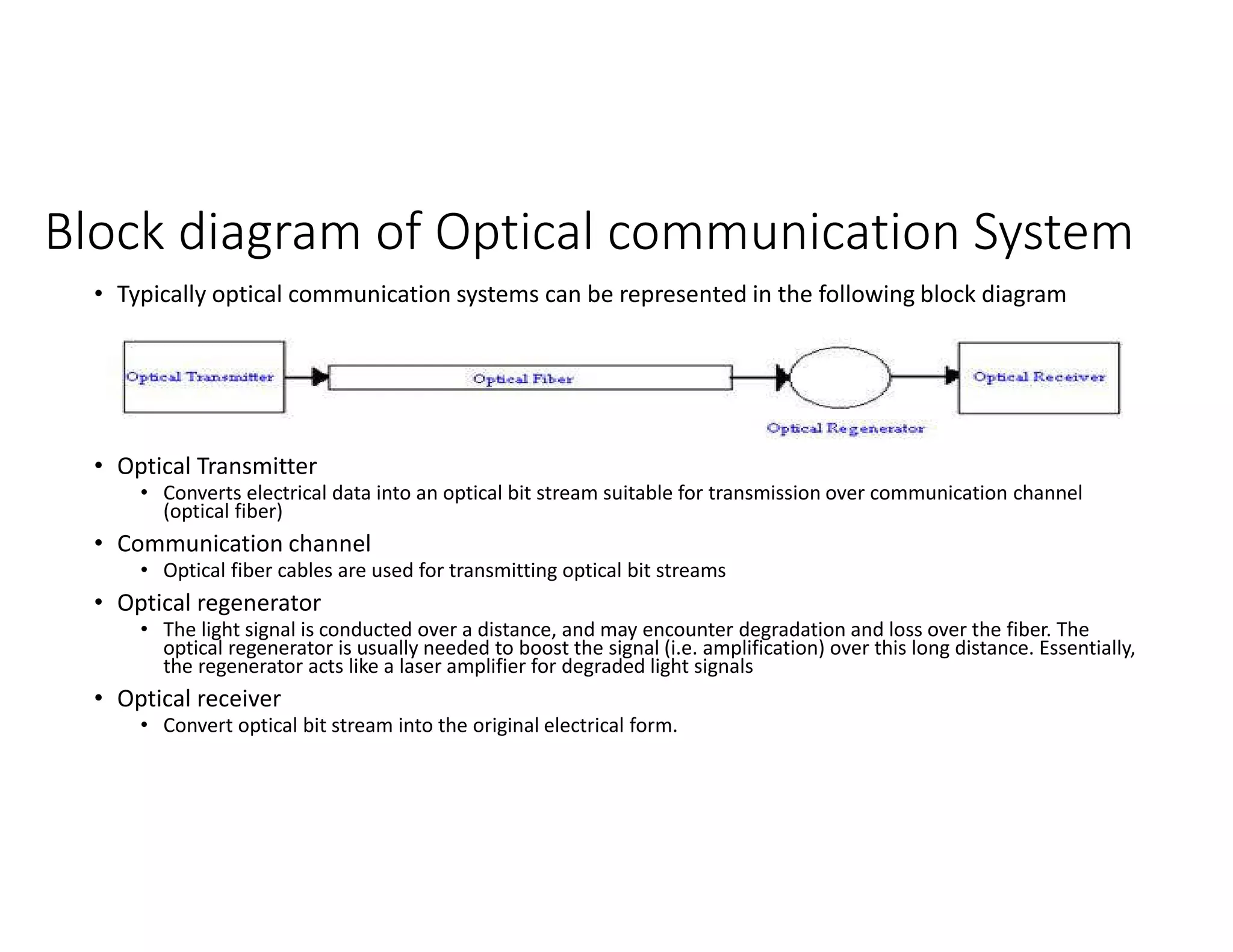
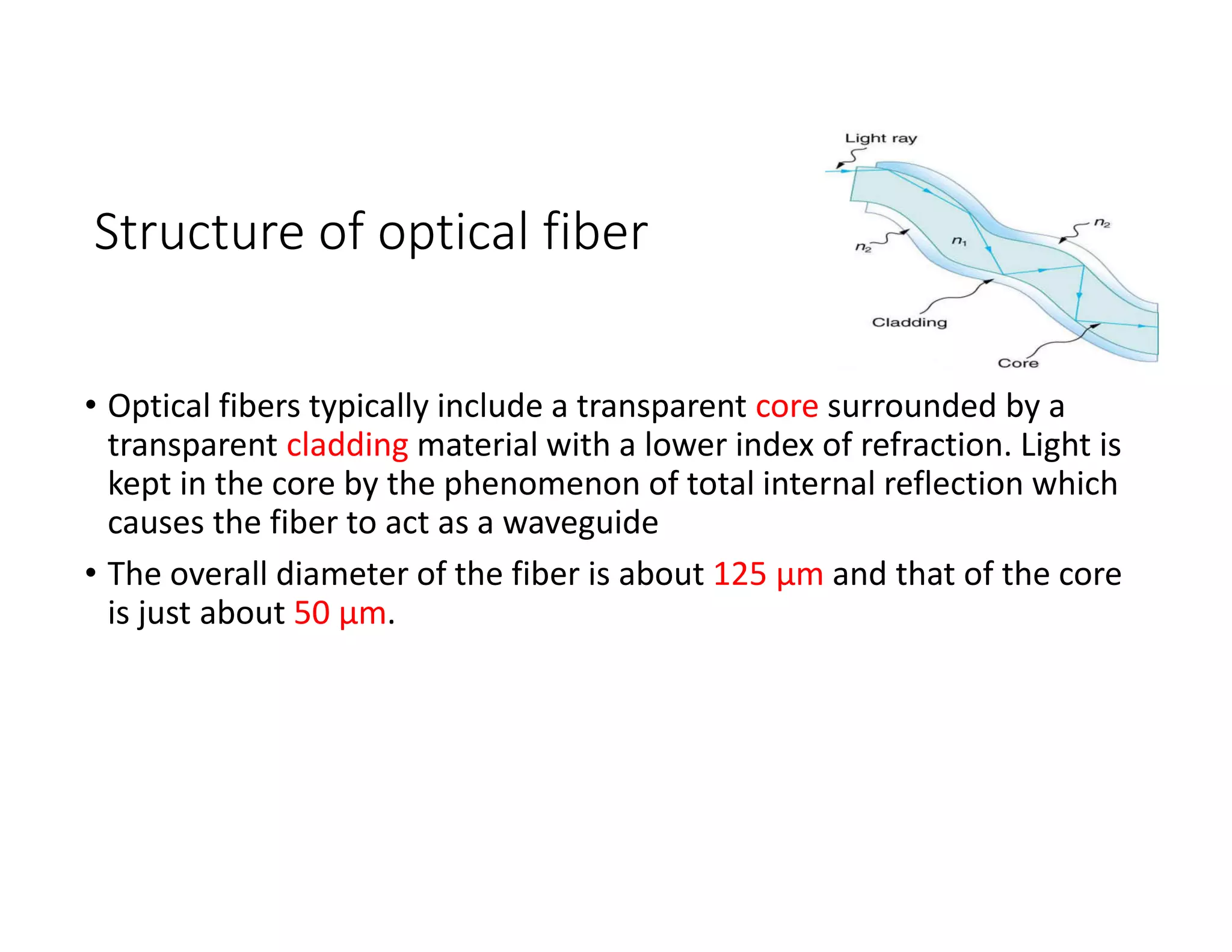
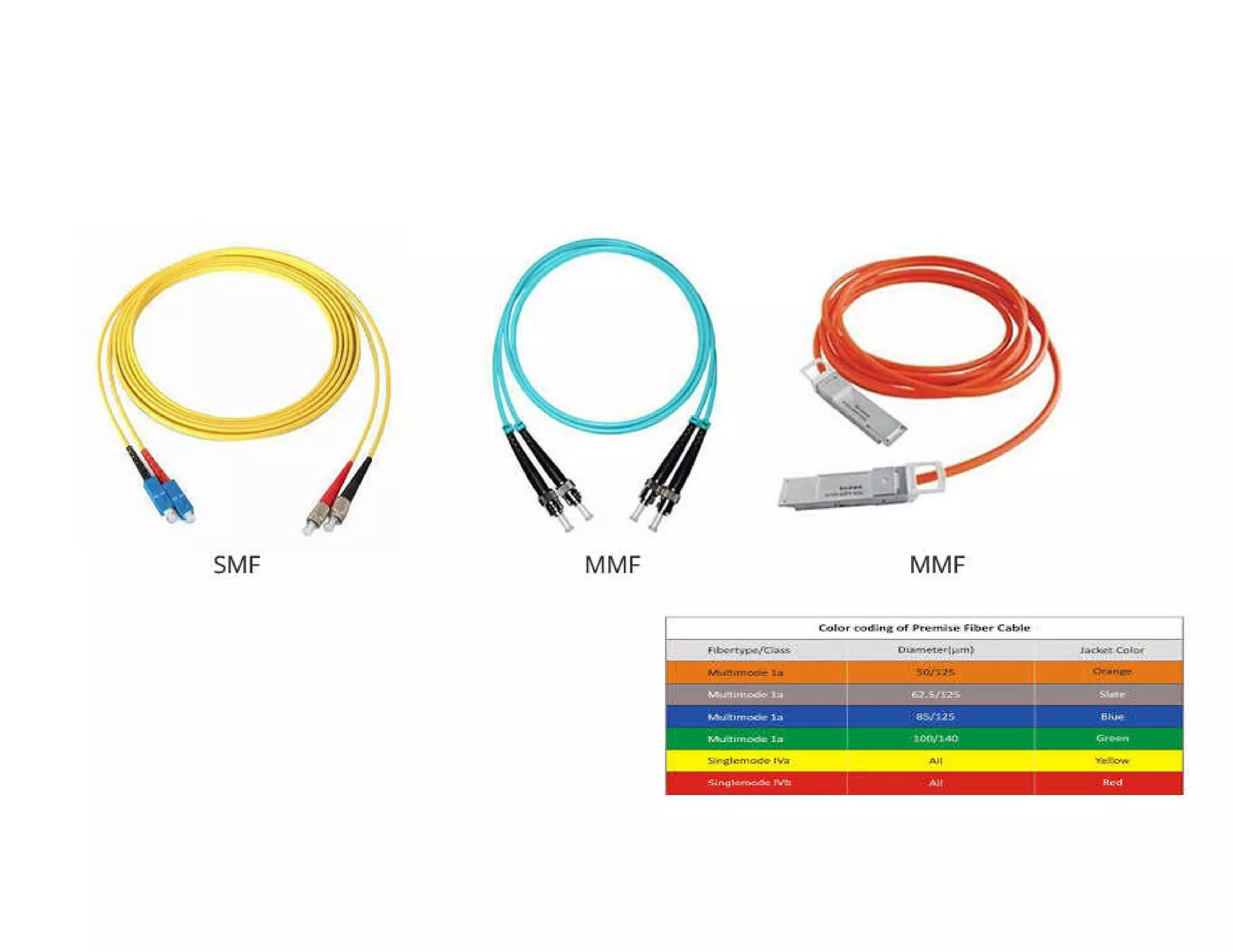
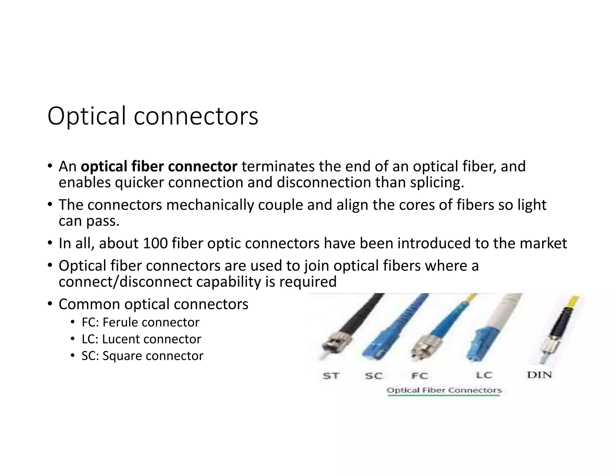
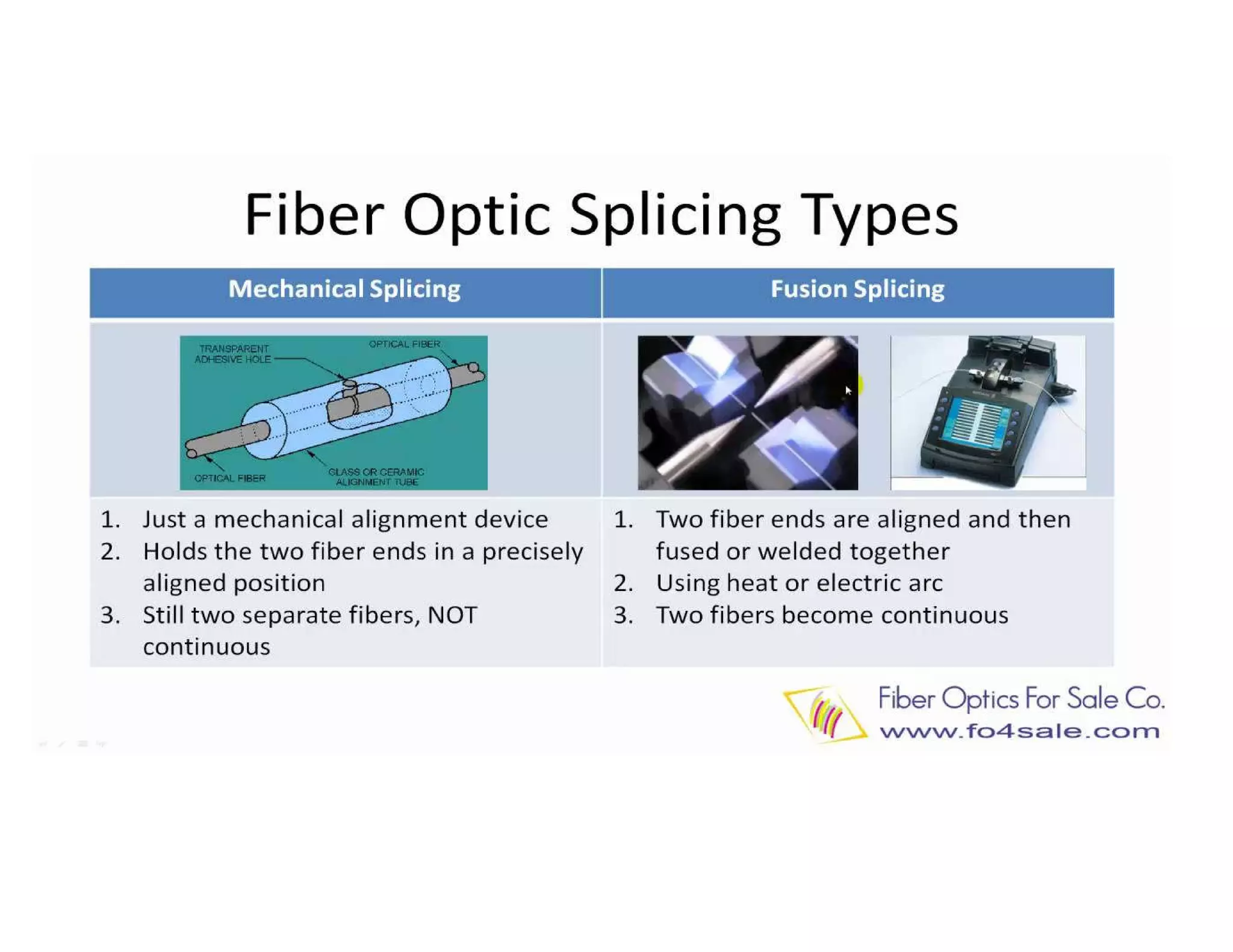
Optical Communication
Optical communication system
• Optical communication system is one that uses light as the carrier of
information.
• Uses glass or plastic fiber cables to contain the light waves and guide them
in a manner similar to the way electromagnetic waves are guided through a
metallic transmission medium.
• Optical fiber cable are the guided transmission medium
• Optical fiber cables have an infinite bandwidth. The information carrying
capacity of any communication system is directly proportional to
bandwidth.
• Light frequencies used in optical communication system are between
1*10E14 Hz and 4*10E14 Hz
• Optical communication system works under the principle of Total Internal
Reflection.
Electromagnetic spectrum used in optical
communication system
• Optical communication system generally operates in the infrared band.
• Infrared band ranges from wavelengths 770 nm to 10^6 nm.
• The most common wavelengths of these light signals are 850 nm, 1310 nm, and 1550 nm.
• Light spectrum is divided into 3 bands
• Infrared band
• Invisible to human eye,
• Wavelength from 770 nm to 10^6 nm
• Visible band
• Visible to human eye,
• Wavelength from 390 nm to 770 nm
• Ultraviolet band
• Invisible to human eye
• Wavelength from 10 nm to 390 nm
Note: It is common to use units of wavelength rather than frequency when dealing with ultra-high frequency electromagnetic
waves.
λ=c/f
Block diagram of Optical communication System
• Typically optical communication systems can be represented in the following block diagram
• Optical Transmitter
• Converts electrical data into an optical bit stream suitable for transmission over communication channel
(optical fiber)
• Communication channel
• Optical fiber cables are used for transmitting optical bit streams
• Optical regenerator
• The light signal is conducted over a distance, and may encounter degradation and loss over the fiber. The
optical regenerator is usually needed to boost the signal (i.e. amplification) over this long distance. Essentially,
the regenerator acts like a laser amplifier for degraded light signals
• Optical receiver
• Convert optical bit stream into the original electrical form.
Optical Transmitter
• The light source (optical transmitter) used is either infrared LED (Light
emitting diode) or ILD ( Injection laser diode).
S.No ILD LED
1 Emits coherent(orderly) light Emits incoherent(disorderly) light
2 Low coupling loss High coupling loss
3 Output power is greater (7dBm) Output power is lesser (-3dBm)
4 Can be operated over longer distance Can only be operated over shorter distance
5 expensive cheaper
6 Shorter life time Longer life time
7 More temperature dependent Less temperature dependent
Optical receivers
• The light detector ( optical receiver) used is either a PIN ( p-type-
intrinsic-n-type) diode, and APD ( avalanche photodiode), or a
phototransistor.
• PIN diodes operates just the opposite of an LED.
• An APD is a pipn structure.
• APDs are more sensitive than PIN diodes and require less additional
amplification.
Total internal reflection
Total Internal Reflection
• Conditions
• Light travel from a medium with higher refractive index to a medium with
lower refractive index
• Angle of incidence greater than critical angle
• Results
• No refraction
• All the light beam will be reflected back to the original medium.
Snell’s law
Snell’s law
• Snell's law (also known the law of refraction)
• is a formula used to describe the relationship between the angles of
incidence and refraction with refractive indexes of different medium.
• It explains how a light ray reacts when it meets the interface of two
different medium that have different indexes of refraction.
• When a light ray travels from denser to lighter medium, angle of refraction
is greater than angle of incidence, i.e, lighter bends away from normal
• When a light ray travels from lighter to denser medium, angle of refraction
is lesser than angle of incidence, i.e, light bends towards the normal.
Optical fiber
• An optical fibre is a thin, transparent fibre, about the diameter of
human hair, usually made of glass (SiO2) or plastic, for transmitting
light.
• Long distance telecommunication systems, however, almost always
use glass (SiO2) because of its lower optical absorption during
transmission to maintain the signal strength.
Structure of optical fiber
• Optical fibers typically include a transparent core surrounded by a
transparent cladding material with a lower index of refraction. Light is
kept in the core by the phenomenon of total internal reflection which
causes the fiber to act as a waveguide
• The overall diameter of the fiber is about 125 μm and that of the core
is just about 50 μm.
Optical fiber types and properties
• Optical fiber is classified into two categories based on
• The number of modes ( modes means path)
• Single Mode Fiber ( SMF)
• Multi Mode Fiber ( MMF)
Jacket color is sometimes used to distinguish multi-mode cables from single-mode ones
The standard TIA-598C recommends, for non-military applications, the use of a yellow
jacket for single-mode fiber and orange or aqua for multi-mode fiber.
• The refractive index
• Step Index
• Graded Index
• Single Mode Fiber ( SMF)
• In single mode fiber only one mode can propagate through the fiber
• There is only one path (mode) for light rays to take down a cable
• Has small core diameter ( 8-10 μm) and high cladding diameter ( 125 μm)
• There is no dispersion, i.e., no degradation of signal during travelling through
the fiber
• Suitable for longer distance and higher capacity
• Light is passed through single mode fiber through laser diode.
• Usually expensive
• Operates at 1310nm, 1550 nm
• Multi Mode Fiber (MMF)
• It allows more than one mode ( path) for the light rays traveling through it.
• The number of modes ( paths) possible for a multi mode fiber depends on frequency(
wavelength) of the light signal, the refractive indexes of the core and cladding, and the core
diameter.
• Large Core diameter of 50 μm and cladding diameter is 125 μm
• Higher light gathering capacity
• Large core allows for the use of LEDs
• There is signal degradation due to multi mode dispersion
• Not suitable for long distance communication due to large dispersion and attenuation of the
signal.
• Typical multi-mode links have data rates of 10 Mbit/s to 10 Gbit/s over link lengths of up to
600 meters (2000 feet).
• Usually less expensive
• Operates at 850nm, 1310 nm
• bandwidth–distance product limit is lower
•Step Index
• Refractive index of core and cladding both are constant.
• There is abrupt change in the refractive index at the
core/cladding interface.
• This is true for both single and multimode step index
fibers.
• Graded Index
• refractive index of the core is non uniform
• Refractive index is highest in the centre of the core and gradually decreases
with distance towards the outer edge.
• Modal dispersion is reduced
• Practically there are 3 types of optical fiber configuration
• Single mode step index
• Multimode step index
• Multimode graded index
Optical connectors
• An optical fiber connector terminates the end of an optical fiber, and
enables quicker connection and disconnection than splicing.
• The connectors mechanically couple and align the cores of fibers so light
can pass.
• In all, about 100 fiber optic connectors have been introduced to the market
• Optical fiber connectors are used to join optical fibers where a
connect/disconnect capability is required
• Common optical connectors
• FC: Ferule connector
• LC: Lucent connector
• SC: Square connector
Splice and Connectors
• Splice is a device or a process used to permanently connect fibers.
• A connector is a device used to allow cables to be joined and
disjoined.
• The basic and common requirements for splices and connectors are
low loss (attenuation) and accurate alignment.
• A splice can be used to extend cable length or repair a break.
• A connector is used to connect the fiber cable to equipment, a
junction box (ODF, optical distribution frame), and so forth.
Optical Splicing
•Two basic types of splicing
1. Mechanical splicing
2. Fusion splicing
• Mechanical Splicing
• A mechanical splice is a junction of two or more optical fibers that are aligned
and held in place by a self-contained assembly (usually the size of a large
carpenter's nail).
• The fibers are not permanently joined, just precisely held together so that
light can pass from one to another.
• The mechanical splice is more suited for field service repair where conditions
are unfavorable for using expensive bulky equipment.
• introduce an attenuation loss of 0.1 dB or less, which is reasonable.
• Fusion Splicing
• Fusion splicing is the act of joining two optical fibers end-to-end using heat.
• The goal is to fuse the two fibers together in such a way that light passing
through the fibers is not scattered or reflected back by the splice, and so that
the splice and the region surrounding it are almost as strong as the virgin fiber
itself.
• The source of heat is usually an electric arc, but can also be a laser, or a gas
flame, or a tungsten filament through which current is passed.
• The fusion splice requires expensive equipment (thousands of dollars) and is
not suited for use under field conditions, for example, in trenches, manholes,
or cables suspended from poles.
• The small Power loss of the fusion splice (0.01 dB or less) and its overall
reliability make it the choice for new indoor installations.
Advantages of optical fiber
• Wider bandwidth and greater information capacity
• Immunity to cross talk
• Immunity to static interference
• Environmental immunity
• Lower transmission loss
• Security
• Durability and reliability
• Economics
Disadvantages of optical fiber
• Strength
• Specialized tools , equipment and training
• Right of way .
• Aerial Optical Fiber
• ADSS: All Dielectric Self Supporting
• OPGW
• All-dielectric self-supporting (ADSS) cable is a type of optical fiber
cable that is strong enough to support itself between structures
without using conductive metal elements.
• No metal wires are used in an ADSS cable.
• Lost cost
• Faster deployment
• OPGW, Optical ground wire
• Such cable combines the functions of grounding and communications
• An OPGW cable contains a tubular structure with one or more optical fibers in
it, surrounded by layers of steel and aluminum wire.
• OPGW cable is run between the tops of high-voltage electricity pylons.
• The conductive part of the cable serves to bond adjacent towers to earth
ground, and shields the high-voltage conductors from lightning strikes.
• Typically OPGW cables contain single-mode optical fibers with low
transmission loss, allowing long distance transmission at high speeds.
Submarine Cable
• Submarine cables means of intercontinental broadband communication
• A submarine communications cable is a cable laid on the sea bed between
land-based stations to carry telecommunication signals across stretches of
ocean.
• Submarine cables are laid using special cable layer ships,
• Submarine cables use principles very much like those of coaxial cables.
Thus they are coaxial, have repeaters and equalizers and have dc power fed
to them, with opposite polarities fed from opposite ends to reduce
insulation problems.
• However, submarine cables use a single coaxial tube for both directions of
transmission, with frequency techniques similar to those of microwave
links to separate the two directions.
Single Mode Fiber
• Advantage
• Minimum dispersion
• Wider bandwidth and higher information carrying capacity
• Long range communication is possible
• Disadvantage
• Difficult to couple light into and out of this type of fiber due to very small core
dimension
• Only highly directive light source such as laser can only be used to couple light
• Expensive and difficult to manufacture
Multimode fiber
• Advantages
• Relatively inexpensive and simple to manufacture
• Easier to couple light into and out of this type of fiber due to relatively large
core dimension
• Disadvantages
• Relatively larger modal dispersion
• Relatively lesser bandwidth and higher information carrying capacity
• Relatively lesser range communication
Multiple graded index fiber
• Easier to couple light into and out of than single mode step index
fiber but are more difficult multimode step index fiber
• Distortion due to multiple propagation paths is greater than in single
mode step index fiber but less than in multiple step index fiber
• Considered as an intermediate fiber compared to the other fiber
types.
Optical Coupling
• Acceptance angle:
• The maximum angle in which external light rays may strike the air/glass interface and
still propagate down the fiber, that result in total internal reflection.
• Depends one the refractive index of core and cladding
• Numerical Aperture:
• Rotating the acceptance angle around the fiber core axis gives the acceptance cone
of fiber input
• It is the light gathering or light collecting capability of an optical fiber
• Ability to couple light into the fiber cable from an external source.
• The larger the magnitude of numerical aperture, the greater the amount of external
light the fiber will accept.
• Critical angle is defines as the minimum value where as acceptance
angle is the maximum value.
• Light rays striking the air/glass interface at an angle greater than
acceptance angle will enter the cladding and therefore will not
propagate down the fiber cable.
Losses in optical fiber cables
• Attenuation that results in reduction in the power of the light wave as
it travels down the fiber cable.
• Attenuation of light propagating through the glass depends on
wavelength
• Predominant losses in optical fiber
• Absorption loss
• Rayleigh ( material) scattering loss
• Chromatic, or wavelength , dispersion
• Bending loss ( radiation)
• Modal dispersion
• Coupling losses
• Absorption loss:
• caused due to impurities in the fiber ,
• light is absorbed and converted to heat
• Material or Rayleigh , scattering loss:
• During manufacturing, some permanent microscopic irregularities are
developed
• light rays propagating down the fiber strike one of these irregularities are
diffracted which cause light to disperse or spread out in many directions
• Some of the diffracted light continues down the fiber and some of it escapes
through the cladding
• The light rays that escape represent a loss in power, called Rayleigh scattering
• Chromatic or wavelength, dispersion:
• Velocity depends upon the wavelength in any medium.
• Each wavelength within the composite light signal travels at different velocity
when propagating through the glass
• Light rays that are simultaneously emitted and propagated down the optical
fiber cable do not arrive at the far end at the same time, resulting in an
impairment called chromatic distortion ( also called wavelength dispersion)
• Can be eliminated by monochromatic light source such as ILD ( injection laser
diode)
• light emitting diode ( LED) emit light containing many wavelengths.
• Radiation loss ( bending loss)
• Caused mainly by small bends
• Generally contribute to 20% of total attenuation in a fiber
• Modal Dispersion ( pulse spreading)
• Caused by difference in the propagation times of light rays that take different paths down a
fiber
• Can occur only in multimode fibers
• Can be reduced considerably by using graded index fibers and almost entirely by using single
mode fibers.
Coupling loss:
• caused by imperfect physical connection
• Can occur at any of the following three types of optical junctions
• Light source to fiber connection
• Fiber to fiber connection
• Fiber to photo detector connection
• Caused by any of the following alignment problems
a) Lateral,axial displacement
b) Gap displacement
c) Angular displacement
d) Imperfect surface finish
Passive optical Network
• implements a point-to-multipoint architecture
• unpowered fiber optic splitters are used to enable a single optical
fiber to serve multiple end-points such as customers, without having
to provision individual fibers between the hub and customer.
• consists of an
• optical line terminal (OLT) at the service provider's central office (hub)
• and a number of optical network units (ONUs) or optical network terminals
(ONTs), near end users
• passive optical network is a form of fiber-optic access network.

Presentation on optical communication.pdf

  • 1.
  • 3.
    Optical communication system •Optical communication system is one that uses light as the carrier of information. • Uses glass or plastic fiber cables to contain the light waves and guide them in a manner similar to the way electromagnetic waves are guided through a metallic transmission medium. • Optical fiber cable are the guided transmission medium • Optical fiber cables have an infinite bandwidth. The information carrying capacity of any communication system is directly proportional to bandwidth. • Light frequencies used in optical communication system are between 1*10E14 Hz and 4*10E14 Hz • Optical communication system works under the principle of Total Internal Reflection.
  • 4.
    Electromagnetic spectrum usedin optical communication system • Optical communication system generally operates in the infrared band. • Infrared band ranges from wavelengths 770 nm to 10^6 nm. • The most common wavelengths of these light signals are 850 nm, 1310 nm, and 1550 nm. • Light spectrum is divided into 3 bands • Infrared band • Invisible to human eye, • Wavelength from 770 nm to 10^6 nm • Visible band • Visible to human eye, • Wavelength from 390 nm to 770 nm • Ultraviolet band • Invisible to human eye • Wavelength from 10 nm to 390 nm Note: It is common to use units of wavelength rather than frequency when dealing with ultra-high frequency electromagnetic waves. λ=c/f
  • 6.
    Block diagram ofOptical communication System • Typically optical communication systems can be represented in the following block diagram • Optical Transmitter • Converts electrical data into an optical bit stream suitable for transmission over communication channel (optical fiber) • Communication channel • Optical fiber cables are used for transmitting optical bit streams • Optical regenerator • The light signal is conducted over a distance, and may encounter degradation and loss over the fiber. The optical regenerator is usually needed to boost the signal (i.e. amplification) over this long distance. Essentially, the regenerator acts like a laser amplifier for degraded light signals • Optical receiver • Convert optical bit stream into the original electrical form.
  • 7.
    Optical Transmitter • Thelight source (optical transmitter) used is either infrared LED (Light emitting diode) or ILD ( Injection laser diode). S.No ILD LED 1 Emits coherent(orderly) light Emits incoherent(disorderly) light 2 Low coupling loss High coupling loss 3 Output power is greater (7dBm) Output power is lesser (-3dBm) 4 Can be operated over longer distance Can only be operated over shorter distance 5 expensive cheaper 6 Shorter life time Longer life time 7 More temperature dependent Less temperature dependent
  • 8.
    Optical receivers • Thelight detector ( optical receiver) used is either a PIN ( p-type- intrinsic-n-type) diode, and APD ( avalanche photodiode), or a phototransistor. • PIN diodes operates just the opposite of an LED. • An APD is a pipn structure. • APDs are more sensitive than PIN diodes and require less additional amplification.
  • 9.
  • 10.
    Total Internal Reflection •Conditions • Light travel from a medium with higher refractive index to a medium with lower refractive index • Angle of incidence greater than critical angle • Results • No refraction • All the light beam will be reflected back to the original medium.
  • 11.
  • 12.
    Snell’s law • Snell'slaw (also known the law of refraction) • is a formula used to describe the relationship between the angles of incidence and refraction with refractive indexes of different medium. • It explains how a light ray reacts when it meets the interface of two different medium that have different indexes of refraction. • When a light ray travels from denser to lighter medium, angle of refraction is greater than angle of incidence, i.e, lighter bends away from normal • When a light ray travels from lighter to denser medium, angle of refraction is lesser than angle of incidence, i.e, light bends towards the normal.
  • 13.
    Optical fiber • Anoptical fibre is a thin, transparent fibre, about the diameter of human hair, usually made of glass (SiO2) or plastic, for transmitting light. • Long distance telecommunication systems, however, almost always use glass (SiO2) because of its lower optical absorption during transmission to maintain the signal strength.
  • 14.
    Structure of opticalfiber • Optical fibers typically include a transparent core surrounded by a transparent cladding material with a lower index of refraction. Light is kept in the core by the phenomenon of total internal reflection which causes the fiber to act as a waveguide • The overall diameter of the fiber is about 125 μm and that of the core is just about 50 μm.
  • 15.
    Optical fiber typesand properties • Optical fiber is classified into two categories based on • The number of modes ( modes means path) • Single Mode Fiber ( SMF) • Multi Mode Fiber ( MMF) Jacket color is sometimes used to distinguish multi-mode cables from single-mode ones The standard TIA-598C recommends, for non-military applications, the use of a yellow jacket for single-mode fiber and orange or aqua for multi-mode fiber. • The refractive index • Step Index • Graded Index
  • 17.
    • Single ModeFiber ( SMF) • In single mode fiber only one mode can propagate through the fiber • There is only one path (mode) for light rays to take down a cable • Has small core diameter ( 8-10 μm) and high cladding diameter ( 125 μm) • There is no dispersion, i.e., no degradation of signal during travelling through the fiber • Suitable for longer distance and higher capacity • Light is passed through single mode fiber through laser diode. • Usually expensive • Operates at 1310nm, 1550 nm
  • 18.
    • Multi ModeFiber (MMF) • It allows more than one mode ( path) for the light rays traveling through it. • The number of modes ( paths) possible for a multi mode fiber depends on frequency( wavelength) of the light signal, the refractive indexes of the core and cladding, and the core diameter. • Large Core diameter of 50 μm and cladding diameter is 125 μm • Higher light gathering capacity • Large core allows for the use of LEDs • There is signal degradation due to multi mode dispersion • Not suitable for long distance communication due to large dispersion and attenuation of the signal. • Typical multi-mode links have data rates of 10 Mbit/s to 10 Gbit/s over link lengths of up to 600 meters (2000 feet). • Usually less expensive • Operates at 850nm, 1310 nm • bandwidth–distance product limit is lower
  • 19.
    •Step Index • Refractiveindex of core and cladding both are constant. • There is abrupt change in the refractive index at the core/cladding interface. • This is true for both single and multimode step index fibers.
  • 20.
    • Graded Index •refractive index of the core is non uniform • Refractive index is highest in the centre of the core and gradually decreases with distance towards the outer edge. • Modal dispersion is reduced
  • 21.
    • Practically thereare 3 types of optical fiber configuration • Single mode step index • Multimode step index • Multimode graded index
  • 22.
    Optical connectors • Anoptical fiber connector terminates the end of an optical fiber, and enables quicker connection and disconnection than splicing. • The connectors mechanically couple and align the cores of fibers so light can pass. • In all, about 100 fiber optic connectors have been introduced to the market • Optical fiber connectors are used to join optical fibers where a connect/disconnect capability is required • Common optical connectors • FC: Ferule connector • LC: Lucent connector • SC: Square connector
  • 23.
    Splice and Connectors •Splice is a device or a process used to permanently connect fibers. • A connector is a device used to allow cables to be joined and disjoined. • The basic and common requirements for splices and connectors are low loss (attenuation) and accurate alignment. • A splice can be used to extend cable length or repair a break. • A connector is used to connect the fiber cable to equipment, a junction box (ODF, optical distribution frame), and so forth.
  • 24.
    Optical Splicing •Two basictypes of splicing 1. Mechanical splicing 2. Fusion splicing
  • 25.
    • Mechanical Splicing •A mechanical splice is a junction of two or more optical fibers that are aligned and held in place by a self-contained assembly (usually the size of a large carpenter's nail). • The fibers are not permanently joined, just precisely held together so that light can pass from one to another. • The mechanical splice is more suited for field service repair where conditions are unfavorable for using expensive bulky equipment. • introduce an attenuation loss of 0.1 dB or less, which is reasonable.
  • 26.
    • Fusion Splicing •Fusion splicing is the act of joining two optical fibers end-to-end using heat. • The goal is to fuse the two fibers together in such a way that light passing through the fibers is not scattered or reflected back by the splice, and so that the splice and the region surrounding it are almost as strong as the virgin fiber itself. • The source of heat is usually an electric arc, but can also be a laser, or a gas flame, or a tungsten filament through which current is passed. • The fusion splice requires expensive equipment (thousands of dollars) and is not suited for use under field conditions, for example, in trenches, manholes, or cables suspended from poles. • The small Power loss of the fusion splice (0.01 dB or less) and its overall reliability make it the choice for new indoor installations.
  • 28.
    Advantages of opticalfiber • Wider bandwidth and greater information capacity • Immunity to cross talk • Immunity to static interference • Environmental immunity • Lower transmission loss • Security • Durability and reliability • Economics
  • 29.
    Disadvantages of opticalfiber • Strength • Specialized tools , equipment and training • Right of way .
  • 30.
    • Aerial OpticalFiber • ADSS: All Dielectric Self Supporting • OPGW
  • 31.
    • All-dielectric self-supporting(ADSS) cable is a type of optical fiber cable that is strong enough to support itself between structures without using conductive metal elements. • No metal wires are used in an ADSS cable. • Lost cost • Faster deployment
  • 32.
    • OPGW, Opticalground wire • Such cable combines the functions of grounding and communications • An OPGW cable contains a tubular structure with one or more optical fibers in it, surrounded by layers of steel and aluminum wire. • OPGW cable is run between the tops of high-voltage electricity pylons. • The conductive part of the cable serves to bond adjacent towers to earth ground, and shields the high-voltage conductors from lightning strikes. • Typically OPGW cables contain single-mode optical fibers with low transmission loss, allowing long distance transmission at high speeds.
  • 33.
    Submarine Cable • Submarinecables means of intercontinental broadband communication • A submarine communications cable is a cable laid on the sea bed between land-based stations to carry telecommunication signals across stretches of ocean. • Submarine cables are laid using special cable layer ships, • Submarine cables use principles very much like those of coaxial cables. Thus they are coaxial, have repeaters and equalizers and have dc power fed to them, with opposite polarities fed from opposite ends to reduce insulation problems. • However, submarine cables use a single coaxial tube for both directions of transmission, with frequency techniques similar to those of microwave links to separate the two directions.
  • 34.
    Single Mode Fiber •Advantage • Minimum dispersion • Wider bandwidth and higher information carrying capacity • Long range communication is possible • Disadvantage • Difficult to couple light into and out of this type of fiber due to very small core dimension • Only highly directive light source such as laser can only be used to couple light • Expensive and difficult to manufacture
  • 35.
    Multimode fiber • Advantages •Relatively inexpensive and simple to manufacture • Easier to couple light into and out of this type of fiber due to relatively large core dimension • Disadvantages • Relatively larger modal dispersion • Relatively lesser bandwidth and higher information carrying capacity • Relatively lesser range communication
  • 36.
    Multiple graded indexfiber • Easier to couple light into and out of than single mode step index fiber but are more difficult multimode step index fiber • Distortion due to multiple propagation paths is greater than in single mode step index fiber but less than in multiple step index fiber • Considered as an intermediate fiber compared to the other fiber types.
  • 37.
  • 38.
    • Acceptance angle: •The maximum angle in which external light rays may strike the air/glass interface and still propagate down the fiber, that result in total internal reflection. • Depends one the refractive index of core and cladding • Numerical Aperture: • Rotating the acceptance angle around the fiber core axis gives the acceptance cone of fiber input • It is the light gathering or light collecting capability of an optical fiber • Ability to couple light into the fiber cable from an external source. • The larger the magnitude of numerical aperture, the greater the amount of external light the fiber will accept.
  • 39.
    • Critical angleis defines as the minimum value where as acceptance angle is the maximum value. • Light rays striking the air/glass interface at an angle greater than acceptance angle will enter the cladding and therefore will not propagate down the fiber cable.
  • 40.
    Losses in opticalfiber cables • Attenuation that results in reduction in the power of the light wave as it travels down the fiber cable. • Attenuation of light propagating through the glass depends on wavelength
  • 41.
    • Predominant lossesin optical fiber • Absorption loss • Rayleigh ( material) scattering loss • Chromatic, or wavelength , dispersion • Bending loss ( radiation) • Modal dispersion • Coupling losses
  • 42.
    • Absorption loss: •caused due to impurities in the fiber , • light is absorbed and converted to heat • Material or Rayleigh , scattering loss: • During manufacturing, some permanent microscopic irregularities are developed • light rays propagating down the fiber strike one of these irregularities are diffracted which cause light to disperse or spread out in many directions • Some of the diffracted light continues down the fiber and some of it escapes through the cladding • The light rays that escape represent a loss in power, called Rayleigh scattering
  • 43.
    • Chromatic orwavelength, dispersion: • Velocity depends upon the wavelength in any medium. • Each wavelength within the composite light signal travels at different velocity when propagating through the glass • Light rays that are simultaneously emitted and propagated down the optical fiber cable do not arrive at the far end at the same time, resulting in an impairment called chromatic distortion ( also called wavelength dispersion) • Can be eliminated by monochromatic light source such as ILD ( injection laser diode) • light emitting diode ( LED) emit light containing many wavelengths.
  • 44.
    • Radiation loss( bending loss) • Caused mainly by small bends • Generally contribute to 20% of total attenuation in a fiber • Modal Dispersion ( pulse spreading) • Caused by difference in the propagation times of light rays that take different paths down a fiber • Can occur only in multimode fibers • Can be reduced considerably by using graded index fibers and almost entirely by using single mode fibers.
  • 45.
    Coupling loss: • causedby imperfect physical connection • Can occur at any of the following three types of optical junctions • Light source to fiber connection • Fiber to fiber connection • Fiber to photo detector connection • Caused by any of the following alignment problems a) Lateral,axial displacement b) Gap displacement c) Angular displacement d) Imperfect surface finish
  • 47.
    Passive optical Network •implements a point-to-multipoint architecture • unpowered fiber optic splitters are used to enable a single optical fiber to serve multiple end-points such as customers, without having to provision individual fibers between the hub and customer. • consists of an • optical line terminal (OLT) at the service provider's central office (hub) • and a number of optical network units (ONUs) or optical network terminals (ONTs), near end users • passive optical network is a form of fiber-optic access network.